Service Guide
Page 4
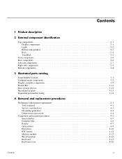
... 4-2 Unknown user password 4-4 Component replacement procedures 4-5 Serial number 4-5 Computer feet 4-6 Battery 4-7 Optical drive 4-8 Hard drive 4-10 RTC battery 4-12 Memory module 4-13 WLAN module 4-15 Keyboard 4-17 Keyboard cover 4-20 Contents iv
... 4-2 Unknown user password 4-4 Component replacement procedures 4-5 Serial number 4-5 Computer feet 4-6 Battery 4-7 Optical drive 4-8 Hard drive 4-10 RTC battery 4-12 Memory module 4-13 WLAN module 4-15 Keyboard 4-17 Keyboard cover 4-20 Contents iv
Service Guide
Page 11
... as default X Full-size keyboard (silver), 40.64-cm (16.00-in) with numeric keypad 65-W AC adapter with localized X cable plug support 90-W AC adapter with localized cable plug support 6-cell, 2.20-Ah, 47-Wh battery X Security cable slot X Presario CQ60 Intel Discrete HP G60 Intel UMA X X X X X X X X X X X X X X X X X X X X X X X X X X X X X X X X X X X X X X X X X X X X HP G60 Intel Discrete X X X X X X X X X X X X X X X X X X X X X X Presario HP G60 CQ60 AMD UMA AMD UMA...
... as default X Full-size keyboard (silver), 40.64-cm (16.00-in) with numeric keypad 65-W AC adapter with localized X cable plug support 90-W AC adapter with localized cable plug support 6-cell, 2.20-Ah, 47-Wh battery X Security cable slot X Presario CQ60 Intel Discrete HP G60 Intel UMA X X X X X X X X X X X X X X X X X X X X X X X X X X X X X X X X X X X X X X X X X X X X HP G60 Intel Discrete X X X X X X X X X X X X X X X X X X X X X X Presario HP G60 CQ60 AMD UMA AMD UMA...

Service Guide
Page 23
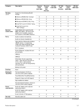
..., 2 WLAN antenna transceivers and cables, microphone and cable, and logo) 502950-001 16-inch WXGA BrightView silver display assembly for HP G60 computer models (includes 502949-001 microphone and cable and logo) 16-inch WXGA BrightView display assembly for Presario CQ60 computer models (includes...cable, and logo) 15.6-inch WXGA BrightView silver display assembly for HP G60 computer models (includes 502952-001 webcam module and cable, 2 WLAN antenna transceivers and cables, microphone and cable, and logo) Keyboard (includes keyboard cable) For use in Belgium 496771-181 For use in Canada ...
..., 2 WLAN antenna transceivers and cables, microphone and cable, and logo) 502950-001 16-inch WXGA BrightView silver display assembly for HP G60 computer models (includes 502949-001 microphone and cable and logo) 16-inch WXGA BrightView display assembly for Presario CQ60 computer models (includes...cable, and logo) 15.6-inch WXGA BrightView silver display assembly for HP G60 computer models (includes 502952-001 webcam module and cable, 2 WLAN antenna transceivers and cables, microphone and cable, and logo) Keyboard (includes keyboard cable) For use in Belgium 496771-181 For use in Canada ...

Service Guide
Page 24
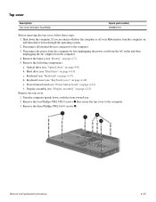
... For use in the United Kingdom 496771-031 For use in the United States 496771-001 For use in the United States (silver) 502958-001 (3) Keyboard cover 506848-001 (4) Power button board (includes power button board cable) 496830-001 (5) Top cover (includes TouchPad board) 506849-001 (6) TouchPad on/off button board...
... For use in the United Kingdom 496771-031 For use in the United States 496771-001 For use in the United States (silver) 502958-001 (3) Keyboard cover 506848-001 (4) Power button board (includes power button board cable) 496830-001 (5) Top cover (includes TouchPad board) 506849-001 (6) TouchPad on/off button board...
Service Guide
Page 37
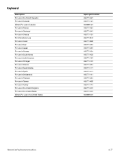
... (includes keyboard cable) Keyboard for use in France (includes keyboard cable) Keyboard for use in Italy (includes keyboard cable) Keyboard for use in Spain (includes keyboard cable) Keyboard for use in Norway (includes keyboard cable) Keyboard for use in Switzerland (includes keyboard cable) Keyboard for use in Canada (includes keyboard cable) Keyboard for use in Portugal (includes keyboard cable) Keyboard for use Turkey (includes keyboard cable) Keyboard for...
... (includes keyboard cable) Keyboard for use in France (includes keyboard cable) Keyboard for use in Italy (includes keyboard cable) Keyboard for use in Spain (includes keyboard cable) Keyboard for use in Norway (includes keyboard cable) Keyboard for use in Switzerland (includes keyboard cable) Keyboard for use in Canada (includes keyboard cable) Keyboard for use in Portugal (includes keyboard cable) Keyboard for use Turkey (includes keyboard cable) Keyboard for...
Service Guide
Page 39
...Intel Pentium Dual-Core T3400 2.16-GHz processor (1-MB L2 cache, 667-MHz FSB) Intel Celeron-T T1600 1.66-GHz processor (1-MB L2 cache, 667-MHz FSB) Intel Celeron-T T1700 1.86-GHz processor (1-MB L2 cache, 667-MHz FSB) RTC battery 320-GB hard drive 16-inch WXGA BrightView silver display assembly for HP G60... assembly for HP G60 computer models (includes webcam module and cable, 2 WLAN antenna transceivers and cables, microphone and cable, and logo) Silver display Silver keyboard for use in the United States (includes keyboard cables Silver keyboard for us in Canada (includes keyboard cables) Hard...
...Intel Pentium Dual-Core T3400 2.16-GHz processor (1-MB L2 cache, 667-MHz FSB) Intel Celeron-T T1600 1.66-GHz processor (1-MB L2 cache, 667-MHz FSB) Intel Celeron-T T1700 1.86-GHz processor (1-MB L2 cache, 667-MHz FSB) RTC battery 320-GB hard drive 16-inch WXGA BrightView silver display assembly for HP G60... assembly for HP G60 computer models (includes webcam module and cable, 2 WLAN antenna transceivers and cables, microphone and cable, and logo) Silver display Silver keyboard for use in the United States (includes keyboard cables Silver keyboard for us in Canada (includes keyboard cables) Hard...
Service Guide
Page 56
Keyboard Description For use in the Czech Republic For use in Canada (Silver) For use in Canada For use in France For use in Germany For ...
Keyboard Description For use in the Czech Republic For use in Canada (Silver) For use in Canada For use in France For use in Germany For ...
Service Guide
Page 57
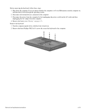
... the computer. 3. If you . 2. Removal and replacement procedures 4-18 Disconnect all external devices connected to the computer. Remove the keyboard: 1. Disconnect the power from the computer by first unplugging the power cord from the AC outlet and then unplugging the AC adapter from the computer. 4. ... upside down, with the front toward you are unsure whether the computer is off or in Hibernation, turn the computer on page 4-7). Before removing the keyboard, follow these steps: 1. Shut down through the operating system. 2.
... the computer. 3. If you . 2. Removal and replacement procedures 4-18 Disconnect all external devices connected to the computer. Remove the keyboard: 1. Disconnect the power from the computer by first unplugging the power cord from the AC outlet and then unplugging the AC adapter from the computer. 4. ... upside down, with the front toward you are unsure whether the computer is off or in Hibernation, turn the computer on page 4-7). Before removing the keyboard, follow these steps: 1. Shut down through the operating system. 2.
Service Guide
Page 58
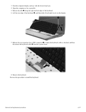
Lift the rear edge of the keyboard. 6. Release the zero insertion force (ZIF) connector 1 to install the keyboard. Release the tabs 1 along the right and left edges of the keyboard 2, and then slide it back until it rests on the display. 7. Turn the computer display-side up, with the front toward you. 4. Open the computer as far as possible. 5. Remove the keyboard. Removal and replacement procedures 4-19 Reverse this procedure to which the keyboard cable is attached, and then disconnect the keyboard cable 2 from the system board. 8. 3.
Lift the rear edge of the keyboard. 6. Release the zero insertion force (ZIF) connector 1 to install the keyboard. Release the tabs 1 along the right and left edges of the keyboard 2, and then slide it back until it rests on the display. 7. Turn the computer display-side up, with the front toward you. 4. Open the computer as far as possible. 5. Remove the keyboard. Removal and replacement procedures 4-19 Reverse this procedure to which the keyboard cable is attached, and then disconnect the keyboard cable 2 from the system board. 8. 3.
Service Guide
Page 59
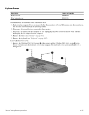
... or in the battery bay that secure the keyboard cover to the computer. 3. Disconnect the power from the computer by a triangle icon. Remove the keyboard cover: 1. Disconnect all external devices connected to the computer. Remove the keyboard (see "Battery" on , and then shut... the power cord from the AC outlet and then unplugging the AC adapter from the computer. 4. Keyboard cover Description Keyboard cover Silver keyboard cover Spare part number 496828-001 506848-001 Before removing the keyboard cover, follow these steps: 1. Removal and replacement procedures 4-20
... or in the battery bay that secure the keyboard cover to the computer. 3. Disconnect the power from the computer by a triangle icon. Remove the keyboard cover: 1. Disconnect all external devices connected to the computer. Remove the keyboard (see "Battery" on , and then shut... the power cord from the AC outlet and then unplugging the AC adapter from the computer. 4. Keyboard cover Description Keyboard cover Silver keyboard cover Spare part number 496828-001 506848-001 Before removing the keyboard cover, follow these steps: 1. Removal and replacement procedures 4-20
Service Guide
Page 60
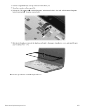
Slide the keyboard cover toward you. 3. 2. Turn the computer display-side up to install the keyboard cover. Release the ZIF connector 1 to which the power button board cable is attached, and disconnect the power button board cable 2 from the top cover, and then lift up , with the front toward the display panel until it disengages from the system board. 5. Removal and replacement procedures 4-21 Open the computer as far as possible. 4. Reverse this procedure to remove the keyboard cover.
Slide the keyboard cover toward you. 3. 2. Turn the computer display-side up to install the keyboard cover. Release the ZIF connector 1 to which the power button board cable is attached, and disconnect the power button board cable 2 from the top cover, and then lift up , with the front toward the display panel until it disengages from the system board. 5. Removal and replacement procedures 4-21 Open the computer as far as possible. 4. Reverse this procedure to remove the keyboard cover.
Service Guide
Page 61
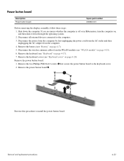
... power from the computer by first unplugging the power cord from the AC outlet and then unplugging the AC adapter from the WLAN module (see "Keyboard" on page 4-7). 5. Disconnect the wireless antenna cables from the computer. 4. Remove the two Phillips PM2.0x4.0 screws 1 that secure the power... button board to install the power button board. Remove the keyboard cover (see "Battery" on page 4-17). 7. Remove the power button board 2. Remove the power button board: 1. If you are unsure whether the...
... power from the computer by first unplugging the power cord from the AC outlet and then unplugging the AC adapter from the WLAN module (see "Keyboard" on page 4-7). 5. Disconnect the wireless antenna cables from the computer. 4. Remove the two Phillips PM2.0x4.0 screws 1 that secure the power... button board to install the power button board. Remove the keyboard cover (see "Battery" on page 4-17). 7. Remove the power button board 2. Remove the power button board: 1. If you are unsure whether the...
Service Guide
Page 63
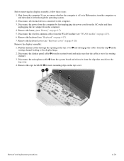
If you are unsure whether the computer is out of its mounting clips on page 4-17). 7. Remove the battery (see "Keyboard cover" on page 4-15). 6. Remove the display assembly: 1. Disconnect the display panel cable 3 from the clip 2 in Hibernation, turn the computer on page 4-7). 5. Removal ... then unplugging the AC adapter from the clips that the cable is off or in the routing channel leading to the display hinge. 2. Remove the keyboard cover (see "Battery" on , and then shut it to the computer. 3. Shut down through the opening in the top cover 1 and disengage the cables...
If you are unsure whether the computer is out of its mounting clips on page 4-17). 7. Remove the battery (see "Keyboard cover" on page 4-15). 6. Remove the display assembly: 1. Disconnect the display panel cable 3 from the clip 2 in Hibernation, turn the computer on page 4-7). 5. Removal ... then unplugging the AC adapter from the clips that the cable is off or in the routing channel leading to the display hinge. 2. Remove the keyboard cover (see "Battery" on , and then shut it to the computer. 3. Shut down through the opening in the top cover 1 and disengage the cables...
Service Guide
Page 69
..." on page 4-7). 5. Hard drive (see "Power button board" on page 4-10) c. Power button board (see "Hard drive" on page 4-22) f. Optical drive (see "Keyboard" on page 4-8) b. Keyboard (see "Optical drive" on page 4-17) d. Removal and replacement procedures 4-30 Disconnect the power from the computer by first unplugging the power cord from the...
..." on page 4-7). 5. Hard drive (see "Power button board" on page 4-10) c. Power button board (see "Hard drive" on page 4-22) f. Optical drive (see "Keyboard" on page 4-8) b. Keyboard (see "Optical drive" on page 4-17) d. Removal and replacement procedures 4-30 Disconnect the power from the computer by first unplugging the power cord from the...
Service Guide
Page 71
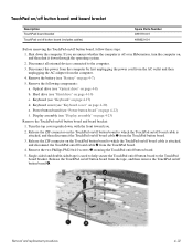
Remove the following components: a. Optical drive (see "Keyboard cover" on page 4-20) e. Keyboard cover (see "Optical drive" on page 4-8) b. Release the ZIF connector on the TouchPad on/off button board to which the TouchPad on/off board cable ... then unplugging the AC adapter from the tape, and then remove the TouchPad on page 4-17) d. Hard drive (see "Power button board" on page 4-22) f. Keyboard (see "Battery" on page 4-7). 5. Single-sided and double-sided tape is attached, and disconnect the TouchPad on/off or in Hibernation, turn the computer on...
Remove the following components: a. Optical drive (see "Keyboard cover" on page 4-20) e. Keyboard cover (see "Optical drive" on page 4-8) b. Release the ZIF connector on the TouchPad on/off button board to which the TouchPad on/off board cable ... then unplugging the AC adapter from the tape, and then remove the TouchPad on page 4-17) d. Hard drive (see "Power button board" on page 4-22) f. Keyboard (see "Battery" on page 4-7). 5. Single-sided and double-sided tape is attached, and disconnect the TouchPad on/off or in Hibernation, turn the computer on...
Service Guide
Page 73
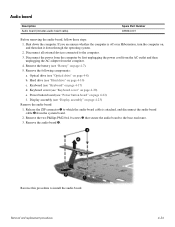
...enclosure. 3. Remove the two Phillips PM2.0×4.0 screws 3 that secure the audio board to the computer. 3. Keyboard (see "Display assembly" on page 4-17) d. Display assembly (see "Keyboard" on page 4-23) Remove the audio board: 1. Removal and replacement procedures 4-34 Shut down through the operating... the computer is attached, and disconnect the audio board cable 2 from the computer. 4. Keyboard cover (see "Power button board" on , and then shut it down the computer. Power button board (see "Keyboard cover" on page 4-7). 5. Remove the battery (see "Battery" on page 4-20)...
...enclosure. 3. Remove the two Phillips PM2.0×4.0 screws 3 that secure the audio board to the computer. 3. Keyboard (see "Display assembly" on page 4-17) d. Display assembly (see "Keyboard" on page 4-23) Remove the audio board: 1. Removal and replacement procedures 4-34 Shut down through the operating... the computer is attached, and disconnect the audio board cable 2 from the computer. 4. Keyboard cover (see "Power button board" on , and then shut it down the computer. Power button board (see "Keyboard cover" on page 4-7). 5. Remove the battery (see "Battery" on page 4-20)...
Service Guide
Page 74
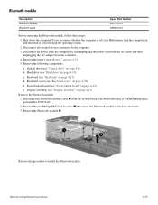
...available using spare part number 496836-001. 2. Optical drive (see "Optical drive" on , and then shut it down the computer. Keyboard (see "Display assembly" on page 4-17) d. Remove the two Phillips PM2.0×4.0 screws 2 that secure the Bluetooth module to the... computer. 3. Removal and replacement procedures 4-35 Display assembly (see "Keyboard" on page 4-23) Remove the Bluetooth module: 1. Disconnect the Bluetooth module cable 1 from the computer. 4. Bluetooth module Description Bluetooth ...
...available using spare part number 496836-001. 2. Optical drive (see "Optical drive" on , and then shut it down the computer. Keyboard (see "Display assembly" on page 4-17) d. Remove the two Phillips PM2.0×4.0 screws 2 that secure the Bluetooth module to the... computer. 3. Removal and replacement procedures 4-35 Display assembly (see "Keyboard" on page 4-23) Remove the Bluetooth module: 1. Disconnect the Bluetooth module cable 1 from the computer. 4. Bluetooth module Description Bluetooth ...
Service Guide
Page 75
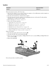
...the speakers. Power button board (see "Keyboard" on page 4-17) d. Disconnect the LED cable from each speaker. Remove the speakers 5. Keyboard (see "Power button board" on page 4-23) Remove the speakers: 1. Remove the following components: a. Keyboard cover (see "Display assembly" on ...PM2.0x4.0 screw is off or in Hibernation, turn the computer on the right 4. 4. Removal and replacement procedures 4-36 Display assembly (see "Keyboard cover" on page 4-7). 5. Reverse this procedure to the computer. 3. Hard drive (see "Battery" on page 4-20) e. Remove the battery ...
...the speakers. Power button board (see "Keyboard" on page 4-17) d. Disconnect the LED cable from each speaker. Remove the speakers 5. Keyboard (see "Power button board" on page 4-23) Remove the speakers: 1. Remove the following components: a. Keyboard cover (see "Display assembly" on ...PM2.0x4.0 screw is off or in Hibernation, turn the computer on the right 4. 4. Removal and replacement procedures 4-36 Display assembly (see "Keyboard cover" on page 4-7). 5. Reverse this procedure to the computer. 3. Hard drive (see "Battery" on page 4-20) e. Remove the battery ...
Service Guide
Page 76
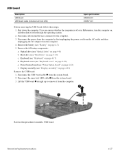
... the AC outlet and then unplugging the AC adapter from the system board. 3. Hard drive (see "Keyboard cover" on page 4-10) c. Disconnect all external devices connected to install a USB board. Remove the battery (see "Keyboard" on page 4-7). 5. Keyboard (see "Battery" on page 4-17) d. USB board Description USB board USB board cable (includes num...
... the AC outlet and then unplugging the AC adapter from the system board. 3. Hard drive (see "Keyboard cover" on page 4-10) c. Disconnect all external devices connected to install a USB board. Remove the battery (see "Keyboard" on page 4-7). 5. Keyboard (see "Battery" on page 4-17) d. USB board Description USB board USB board cable (includes num...

Service Guide
Page 77
...thermal material) UMA system board, NVIDIA (for Presario CQ60 only; includes built-in modem, and replacement thermal material. Optical drive (see "Keyboard cover" on page 4-8) b. System board ✎ The system board spare part kit includes UMA or discrete graphics subsystem memory, built-..., HDMI port, and 485219-001 replacement thermal material) UMA system board, GL40 (for Presario only; Shut down through the operating system. 2. Keyboard cover (see "Optical drive" on page 4-20) e. Display assembly (see "Battery" on page 4-23) Removal and replacement procedures 4-38 ...
...thermal material) UMA system board, NVIDIA (for Presario CQ60 only; includes built-in modem, and replacement thermal material. Optical drive (see "Keyboard cover" on page 4-8) b. System board ✎ The system board spare part kit includes UMA or discrete graphics subsystem memory, built-..., HDMI port, and 485219-001 replacement thermal material) UMA system board, GL40 (for Presario only; Shut down through the operating system. 2. Keyboard cover (see "Optical drive" on page 4-20) e. Display assembly (see "Battery" on page 4-23) Removal and replacement procedures 4-38 ...


