Maintenance and Service Guide
Page 7
... discharge damage ...25 Packaging and transporting guidelines 27 Workstation guidelines 27 5 Removal and replacement procedures for Customer Self-Repair parts 29 Component replacement procedures ...29 Battery ...29 SIM ...30 vii
... discharge damage ...25 Packaging and transporting guidelines 27 Workstation guidelines 27 5 Removal and replacement procedures for Customer Self-Repair parts 29 Component replacement procedures ...29 Battery ...29 SIM ...30 vii
Maintenance and Service Guide
Page 8
Hard drive cover ...32 Hard drive/SSD drive ...33 mSATA drive ...35 RTC battery ...37 Service cover ...38 Memory module ...39 WWAN module ...41 WLAN module ...43 Keyboard ...45 6 Removal and replacement procedures for Authorized Service Provider parts 49 ...
Hard drive cover ...32 Hard drive/SSD drive ...33 mSATA drive ...35 RTC battery ...37 Service cover ...38 Memory module ...39 WWAN module ...41 WLAN module ...43 Keyboard ...45 6 Removal and replacement procedures for Authorized Service Provider parts 49 ...

Maintenance and Service Guide
Page 10
... Using Windows operating system media (purchased separately 97 Using Windows Refresh or Windows Reset 97 Using HP Software Setup ...97 13 Backup and recovery in Windows 10 ...98 Creating recovery media and backups ...98 Creating HP Recovery media (select products only 98 Using Windows tools ...99 Restore and recovery ...100 Recovering using... Questions and answers ...112 16 Power cord set requirements ...113 Requirements for all countries ...113 Requirements for specific countries and regions 113 17 Recycling ...115 Battery ...115 x
... Using Windows operating system media (purchased separately 97 Using Windows Refresh or Windows Reset 97 Using HP Software Setup ...97 13 Backup and recovery in Windows 10 ...98 Creating recovery media and backups ...98 Creating HP Recovery media (select products only 98 Using Windows tools ...99 Restore and recovery ...100 Recovering using... Questions and answers ...112 16 Power cord set requirements ...113 Requirements for all countries ...113 Requirements for specific countries and regions 113 17 Recycling ...115 Battery ...115 x

Maintenance and Service Guide
Page 14
... built into display assembly Secured by subscriber identity module (SIM, user-accessible behind battery) Support for the following WWAN formats: ● HP lt4112 LTE/HSPA+ Mobile Broadband Module ● HP lt4211 LTE/EV-DO/HSPA+ Gobi 4G Module ● HP hs3110 HSPA+ Mobile Broadband Module Supports no WWAN option Supports WWAN after market option...
... built into display assembly Secured by subscriber identity module (SIM, user-accessible behind battery) Support for the following WWAN formats: ● HP lt4112 LTE/HSPA+ Mobile Broadband Module ● HP lt4211 LTE/EV-DO/HSPA+ Gobi 4G Module ● HP hs3110 HSPA+ Mobile Broadband Module Supports no WWAN option Supports WWAN after market option...
Maintenance and Service Guide
Page 15
...and auto-detection for use in Japan Supports the following batteries: ● Primary: 4-cell, 52-Wh, 3.55-Ah battery ● Secondary: 6-cell, 60-Wh, 2.7-Ah battery Supports the following power cords: ● 2 wire... plug (1.0 m) ● 3 wire plug with ground pin (1.0 m) ● 3 wire plug with ground pin (1.8 m) Supports security cable lock Supports fingerprint reader and no fingerprint reader option Supports Trusted Platform Module (TPM) 1.2 (Infineon, soldered down) Integrated Smart Card reader (active) Full volume encryption HP...
...and auto-detection for use in Japan Supports the following batteries: ● Primary: 4-cell, 52-Wh, 3.55-Ah battery ● Secondary: 6-cell, 60-Wh, 2.7-Ah battery Supports the following power cords: ● 2 wire... plug (1.0 m) ● 3 wire plug with ground pin (1.0 m) ● 3 wire plug with ground pin (1.8 m) Supports security cable lock Supports fingerprint reader and no fingerprint reader option Supports Trusted Platform Module (TPM) 1.2 (Infineon, soldered down) Integrated Smart Card reader (active) Full volume encryption HP...
Maintenance and Service Guide
Page 16
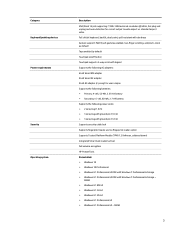
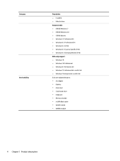
...; Windows 8.1 Enterprise 64 ● Windows 7 Professional 64- and 32-bit ● Windows 7 Enterprise 64- and 32-bit End user replaceable parts: ● AC adapter ● Battery ● Hard drive ● Solid-state drive ● Keyboard ● Memory module ● mSATA flash cache ● WLAN module ● WWAN module 4 Chapter 1 Product description...
...; Windows 8.1 Enterprise 64 ● Windows 7 Professional 64- and 32-bit ● Windows 7 Enterprise 64- and 32-bit End user replaceable parts: ● AC adapter ● Battery ● Hard drive ● Solid-state drive ● Keyboard ● Memory module ● mSATA flash cache ● WLAN module ● WWAN module 4 Chapter 1 Product description...

Maintenance and Service Guide
Page 22
...keypad on . ● Blinking: The computer is in Hibernation. Hibernation is off power to 89 percent. ● Blinking amber: A battery that uses the least amount of the key. NOTE: For select models, the Intel® Rapid Start Technology feature is the only available ... are off when pressed in the upper-right corner of power. Each key on . Component (1) Wireless light (2) Power light (3) AC adapter/Battery light 10 Chapter 2 External component identification Description White: An integrated wireless device, such as a wireless local area network (WLAN) device and/or...
...keypad on . ● Blinking: The computer is in Hibernation. Hibernation is off power to 89 percent. ● Blinking amber: A battery that uses the least amount of the key. NOTE: For select models, the Intel® Rapid Start Technology feature is the only available ... are off when pressed in the upper-right corner of power. Each key on . Component (1) Wireless light (2) Power light (3) AC adapter/Battery light 10 Chapter 2 External component identification Description White: An integrated wireless device, such as a wireless local area network (WLAN) device and/or...
Maintenance and Service Guide
Page 23
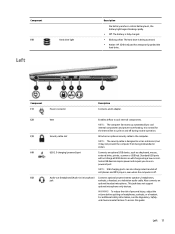
... jack earbuds, a headset, or a television audio cable. Component (4) Hard drive light Left Description the battery reaches a critical battery level, the battery light begins blinking rapidly. ● Off: The battery is fully charged. ● Blinking white: The hard drive is off during routine operation. (3) Security...Connects an optional USB device, such as a deterrent, but it may not prevent the computer from being accessed. ● Amber: HP 3D DriveGuard has temporarily parked the hard drive. To access this guide: Left 11 NOTE: The security cable is normal for the ...
... jack earbuds, a headset, or a television audio cable. Component (4) Hard drive light Left Description the battery reaches a critical battery level, the battery light begins blinking rapidly. ● Off: The battery is fully charged. ● Blinking white: The hard drive is off during routine operation. (3) Security...Connects an optional USB device, such as a deterrent, but it may not prevent the computer from being accessed. ● Amber: HP 3D DriveGuard has temporarily parked the hard drive. To access this guide: Left 11 NOTE: The security cable is normal for the ...
Maintenance and Service Guide
Page 25
... warning message, remove the module to cool internal components. or - Enable airflow to restore computer functionality, and then contact support through HP Support Assistant. It is normal for use in the computer by the governmental agency that regulates wireless devices in Windows 8.1, from the ...Start screen, select the HP Support Assistant app. To access HP Support Assistant in your country or region. Connects an optional travel battery. Bottom 13 NOTE: The computer fan starts up automatically to cycle on and off...
... warning message, remove the module to cool internal components. or - Enable airflow to restore computer functionality, and then contact support through HP Support Assistant. It is normal for use in the computer by the governmental agency that regulates wireless devices in Windows 8.1, from the ...Start screen, select the HP Support Assistant app. To access HP Support Assistant in your country or region. Connects an optional travel battery. Bottom 13 NOTE: The computer fan starts up automatically to cycle on and off...
Maintenance and Service Guide
Page 26
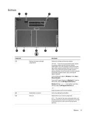
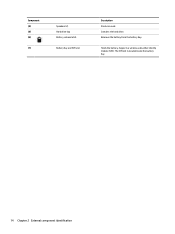
The SIM slot is located inside the battery bay. 14 Chapter 2 External component identification Supports a wireless subscriber identity module (SIM). Component (4) (5) (6) (7) Speakers (2) Hard drive bay Battery release latch Battery bay and SIM slot Description Produce sound. Releases the battery from the battery bay. Contains the hard drive. Holds the battery.
The SIM slot is located inside the battery bay. 14 Chapter 2 External component identification Supports a wireless subscriber identity module (SIM). Component (4) (5) (6) (7) Speakers (2) Hard drive bay Battery release latch Battery bay and SIM slot Description Produce sound. Releases the battery from the battery bay. Contains the hard drive. Holds the battery.
Maintenance and Service Guide
Page 27
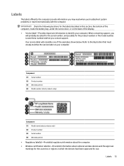
... devices have been approved for use. Refer to the illustration that most closely matches the service label on the back of the computer, inside the battery bay, under the service door, or on your computer. Your service label will probably be asked for the serial number, and possibly for the countries...
... devices have been approved for use. Refer to the illustration that most closely matches the service label on the back of the computer, inside the battery bay, under the service door, or on your computer. Your service label will probably be asked for the serial number, and possibly for the countries...
Maintenance and Service Guide
Page 30
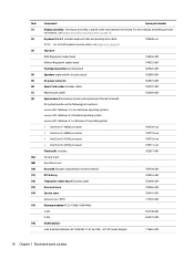
... i5-4210U processor 769717-xxx Plastics Kit, includes: 702877-001 SD card insert Hard drive cover Heat sink (includes replacement thermal material): 769708-001 RTC battery 702853-001 Fingerprint reader board (includes cable) 702845-001 Base enclosure 702863-001 Service cover 704441-001 Service cover, RCTO 713547-001 Memory modules (PC3L...
... i5-4210U processor 769717-xxx Plastics Kit, includes: 702877-001 SD card insert Hard drive cover Heat sink (includes replacement thermal material): 769708-001 RTC battery 702853-001 Fingerprint reader board (includes cable) 702845-001 Base enclosure 702863-001 Service cover 704441-001 Service cover, RCTO 713547-001 Memory modules (PC3L...
Maintenance and Service Guide
Page 31
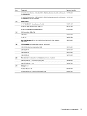
... a/b/g/n (2x2) combination WiFi and Bluetooth 747833-001 4.0 WLAN module for use in Indonesia (17) WWAN module: HP lt4112 LTE/HSPA+ Mobile Broadband Module 740011-001 HP lt4211 LTE/EV-DO/HSPA+ Gobi 4G Module 793116-001 HP hs3110 HSPA+ Mobile Broadband Module 822828-001 (18) Solid-state drive (SSD), M.2: 120-GB, M.2 769712-001... include hard drive bracket, connector, or screws): 500-GB, 7200-rpm, 7-mm, self-encrypting drive 703268-001 500-GB, 7200-rpm, 7-mm 703267-001 (21) Battery (Li ion): 4-cell, 52-Wh, 3.55-Ah 687945-001 6-cell, 60-Wh, 2.7-Ah (travel...
... a/b/g/n (2x2) combination WiFi and Bluetooth 747833-001 4.0 WLAN module for use in Indonesia (17) WWAN module: HP lt4112 LTE/HSPA+ Mobile Broadband Module 740011-001 HP lt4211 LTE/EV-DO/HSPA+ Gobi 4G Module 793116-001 HP hs3110 HSPA+ Mobile Broadband Module 822828-001 (18) Solid-state drive (SSD), M.2: 120-GB, M.2 769712-001... include hard drive bracket, connector, or screws): 500-GB, 7200-rpm, 7-mm, self-encrypting drive 703268-001 500-GB, 7200-rpm, 7-mm 703267-001 (21) Battery (Li ion): 4-cell, 52-Wh, 3.55-Ah 687945-001 6-cell, 60-Wh, 2.7-Ah (travel...

Maintenance and Service Guide
Page 41
... down on the service tag at the bottom of your warranty. Component replacement procedures 29 Check your warranty to release the battery. Make special note of warranty, are as many as 14 screws that must be removed, replaced, or loosened when servicing... Illustrated parts catalog on -screen instructions. Disconnect all locations. Position the computer upside-down through the operating system. 2. NOTE: HP continually improves and changes product parts. Component replacement procedures This chapter provides removal and replacement procedures for details. NOTE: Details about ...
... down on the service tag at the bottom of your warranty. Component replacement procedures 29 Check your warranty to release the battery. Make special note of warranty, are as many as 14 screws that must be removed, replaced, or loosened when servicing... Illustrated parts catalog on -screen instructions. Disconnect all locations. Position the computer upside-down through the operating system. 2. NOTE: HP continually improves and changes product parts. Component replacement procedures This chapter provides removal and replacement procedures for details. NOTE: Details about ...
Maintenance and Service Guide
Page 42
...reassembling the computer. NOTE: In the locked position there will be removed before disassembling the computer. NOTE: This section applies only to lock the battery. If you are unsure whether the computer is off the computer. Disconnect all external devices from the computer. 3. NOTE: If there is ...located inside the battery bay on page 29). The SIM slot is a SIM inserted in on , and then shut it down through the operating system. 2. Press...
...reassembling the computer. NOTE: In the locked position there will be removed before disassembling the computer. NOTE: This section applies only to lock the battery. If you are unsure whether the computer is off the computer. Disconnect all external devices from the computer. 3. NOTE: If there is ...located inside the battery bay on page 29). The SIM slot is a SIM inserted in on , and then shut it down through the operating system. 2. Press...

Maintenance and Service Guide
Page 44
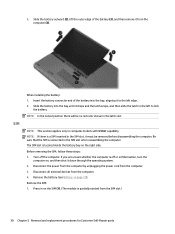
... the 2 captive hard drive cover screws (1). 2. Slide the hard drive cover away from the computer (2), and then lift the cover off the computer. Remove the battery (see Battery on , and then shut it down through the operating system. 2.
... the 2 captive hard drive cover screws (1). 2. Slide the hard drive cover away from the computer (2), and then lift the cover off the computer. Remove the battery (see Battery on , and then shut it down through the operating system. 2.

Maintenance and Service Guide
Page 45
... page 29). 5. Hard drive/SSD drive NOTE: The hard drive spare part kit does not include the hard drive bracket, connector, or screws. Remove the battery (see Hard drive cover on , and then shut it down through the operating system. 2. Remove the hard drive: 1. Pull the hard drive tab (2) upward to...
... page 29). 5. Hard drive/SSD drive NOTE: The hard drive spare part kit does not include the hard drive bracket, connector, or screws. Remove the battery (see Hard drive cover on , and then shut it down through the operating system. 2. Remove the hard drive: 1. Pull the hard drive tab (2) upward to...
Maintenance and Service Guide
Page 47
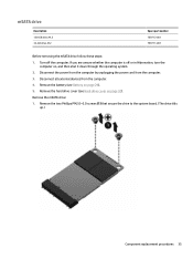
If you are unsure whether the computer is off the computer. Remove the hard drive cover (see Battery on page 29). 5. Remove the mSATA drive: 1. Disconnect all external devices from the computer. 3. Disconnect the power from the computer by unplugging the power cord .... 4. Remove the two Phillips PM2.0×3.0 screws (1) that secure the drive to the system board. (The drive tilts up.) Component replacement procedures 35 Remove the battery (see Hard drive cover on , and then shut it down through the operating system. 2. Turn off or in Hibernation, turn the computer on page 32...
If you are unsure whether the computer is off the computer. Remove the hard drive cover (see Battery on page 29). 5. Remove the mSATA drive: 1. Disconnect all external devices from the computer. 3. Disconnect the power from the computer by unplugging the power cord .... 4. Remove the two Phillips PM2.0×3.0 screws (1) that secure the drive to the system board. (The drive tilts up.) Component replacement procedures 35 Remove the battery (see Hard drive cover on , and then shut it down through the operating system. 2. Turn off or in Hibernation, turn the computer on page 32...
Maintenance and Service Guide
Page 49
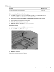
... cable and double-sided tape) Spare part number 702853-001 Before removing the RTC battery, follow these steps: 1. Turn off or in Hibernation, turn the computer on, and then shut it down through the operating system. 2. Disconnect the power... the power cord from the computer. 3. Remove the battery (see Hard drive cover on page 29). 5. Detach the RTC battery (2) from the computer. 3. Remove the hard drive cover (see Battery on page 32). Reverse this procedure to install the RTC battery. Remove the RTC battery: 1. Component replacement procedures 37 If you are unsure ...
... cable and double-sided tape) Spare part number 702853-001 Before removing the RTC battery, follow these steps: 1. Turn off or in Hibernation, turn the computer on, and then shut it down through the operating system. 2. Disconnect the power... the power cord from the computer. 3. Remove the battery (see Hard drive cover on page 29). 5. Detach the RTC battery (2) from the computer. 3. Remove the hard drive cover (see Battery on page 32). Reverse this procedure to install the RTC battery. Remove the RTC battery: 1. Component replacement procedures 37 If you are unsure ...
Maintenance and Service Guide
Page 50
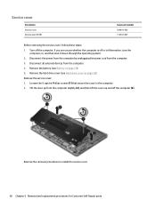
... Self-Repair parts Disconnect the power from the computer by unplugging the power cord from the computer. 4. Remove the hard drive cover (see Battery on page 29). 5. Remove the battery (see Hard drive cover on , and then shut it down through the operating system. 2. Reverse the removal procedures to the computer. 2. Tilt...
... Self-Repair parts Disconnect the power from the computer by unplugging the power cord from the computer. 4. Remove the hard drive cover (see Battery on page 29). 5. Remove the battery (see Hard drive cover on , and then shut it down through the operating system. 2. Reverse the removal procedures to the computer. 2. Tilt...


