
HP Color LaserJet CP3525 Series Printers - Manage and maintain
Page 6
... the print cartridge until it clicks into place. 8 Close the front door. © 2008 Copyright Hewlett-Packard Development Company, L.P. 6 www.hp.com HP Color LaserJet CP3525 Series - CAUTION: Do not touch the green roller. Manage and maintain How do I? CAUTION: Avoid prolonged exposure to perform 5 Grasp both sides of the print cartridge and distribute the...
... the print cartridge until it clicks into place. 8 Close the front door. © 2008 Copyright Hewlett-Packard Development Company, L.P. 6 www.hp.com HP Color LaserJet CP3525 Series - CAUTION: Do not touch the green roller. Manage and maintain How do I? CAUTION: Avoid prolonged exposure to perform 5 Grasp both sides of the print cartridge and distribute the...

HP Color LaserJet CP3525 Series Printers - Manage and maintain
Page 10
Near the bottom of the right side, squeeze the two white levers upward to remove it. © 2008 Copyright Hewlett-Packard Development Company, L.P. 10 www.hp.com Remove any jammed paper, and close the door. 8 If paper is visible entering the bottom of the pickup area. 7 Look for paper in the Tray 2 roller area. HP Color LaserJet CP3525 Series - Manage and maintain How do I? Clear jams in the right door (continued) Steps to perform 5 Close the paper-feed cover. 6 Gently pull the paper out of the fuser, gently pull downward to release the jam-access door.
Near the bottom of the right side, squeeze the two white levers upward to remove it. © 2008 Copyright Hewlett-Packard Development Company, L.P. 10 www.hp.com Remove any jammed paper, and close the door. 8 If paper is visible entering the bottom of the pickup area. 7 Look for paper in the Tray 2 roller area. HP Color LaserJet CP3525 Series - Manage and maintain How do I? Clear jams in the right door (continued) Steps to perform 5 Close the paper-feed cover. 6 Gently pull the paper out of the fuser, gently pull downward to release the jam-access door.

HP Color LaserJet CP3525 Series Printers - Manage and maintain
Page 11
.... Remove the fuser to check for the fuser to cool before handling it. CAUTION: Even if the body of the fuser has cooled, the rollers that are inside could be jammed inside the fuser, gently pull it straight up slightly, and pull out the fuser. Do not touch the fuser... is in the right door (continued) Steps to remove it would not be hot. HP Color LaserJet CP3525 Series - Clear jams in use. CAUTION: The fuser can affect print quality. CAUTION: Do not touch the rollers on the transfer roller. Contaminates can be hot while the product is jammed inside the fuser where it ....
.... Remove the fuser to check for the fuser to cool before handling it. CAUTION: Even if the body of the fuser has cooled, the rollers that are inside could be jammed inside the fuser, gently pull it straight up slightly, and pull out the fuser. Do not touch the fuser... is in the right door (continued) Steps to remove it would not be hot. HP Color LaserJet CP3525 Series - Clear jams in use. CAUTION: The fuser can affect print quality. CAUTION: Do not touch the rollers on the transfer roller. Contaminates can be hot while the product is jammed inside the fuser where it ....
HP Color LaserJet CP3525 Series Printers - User Guide
Page 38
... HP Color LaserJet CP3525 printer and the HP Color LaserJet CP3525n printer. When the cleaning process runs, a cleaning page is on . NOTE: For the HP Color LaserJet CP3525 printer and the HP Color LaserJet CP3525n printer,... you to print the cleaning page. Prints a page of instructions for cleaning excess toner off both trapping and adaptive halftoning. ● LIGHT sets trapping at a medium level and adaptive halftoning is on , this option specifies the number of adjacent objects slightly. ● OFF turns off the pressure roller...
... HP Color LaserJet CP3525 printer and the HP Color LaserJet CP3525n printer. When the cleaning process runs, a cleaning page is on . NOTE: For the HP Color LaserJet CP3525 printer and the HP Color LaserJet CP3525n printer,... you to print the cleaning page. Prints a page of instructions for cleaning excess toner off both trapping and adaptive halftoning. ● LIGHT sets trapping at a medium level and adaptive halftoning is on , this option specifies the number of adjacent objects slightly. ● OFF turns off the pressure roller...
HP Color LaserJet CP3525 Series Printers - User Guide
Page 157
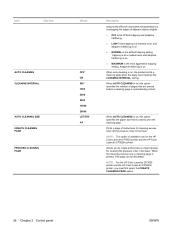
Remove the orange protective cover from the print cartridge. CAUTION: Do not touch the green roller. Doing so can damage the cartridge. 7. ENWW Replace supplies 145 Align the print cartridge with its slot and insert the print cartridge until it clicks into place. 8. Close the front door. CAUTION: Avoid prolonged exposure to light. 6.
Remove the orange protective cover from the print cartridge. CAUTION: Do not touch the green roller. Doing so can damage the cartridge. 7. ENWW Replace supplies 145 Align the print cartridge with its slot and insert the print cartridge until it clicks into place. 8. Close the front door. CAUTION: Avoid prolonged exposure to light. 6.

HP Color LaserJet CP3525 Series Printers - User Guide
Page 198
... Remove any excess paper from Tray 1. Make sure that meets HP specifications. The paper is installed incorrectly. Reload the paper into the output bin. The rollers are not adjusted correctly. Replace the paper. The HP postcard media insert is removed before removing it . See Load ...15 cm) paper. Verify that has already passed through a product Do not use the HP postcard media insert when printing on 4 x 6 in the trays. Or Always use paper that the transfer belt and transfer roller are printing on 4 x 6 in (10 x 15 cm) paper. If the product...
... Remove any excess paper from Tray 1. Make sure that meets HP specifications. The paper is installed incorrectly. Reload the paper into the output bin. The rollers are not adjusted correctly. Replace the paper. The HP postcard media insert is removed before removing it . See Load ...15 cm) paper. Verify that has already passed through a product Do not use the HP postcard media insert when printing on 4 x 6 in the trays. Or Always use paper that the transfer belt and transfer roller are printing on 4 x 6 in (10 x 15 cm) paper. If the product...
HP Color LaserJet CP3525 Series Printers - User Guide
Page 202
... Solve problems ENWW Gently pull the paper out of the right side, squeeze the two white levers upward to check for paper in the Tray 2 roller area. Near the bottom of the pickup area. 7. Paper could be visible. 6. Remove the fuser to release the jam-access door. Contaminates can affect print... quality. 9. Remove any jammed paper, and close the door. 8. Look for jammed paper inside the fuser where it . CAUTION: Do not touch the rollers on the transfer...
... Solve problems ENWW Gently pull the paper out of the right side, squeeze the two white levers upward to check for paper in the Tray 2 roller area. Near the bottom of the pickup area. 7. Paper could be visible. 6. Remove the fuser to release the jam-access door. Contaminates can affect print... quality. 9. Remove any jammed paper, and close the door. 8. Look for jammed paper inside the fuser where it . CAUTION: Do not touch the rollers on the transfer...

HP Color LaserJet CP3525 Series Printers - User Guide
Page 203
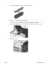
Open the jam-access door. CAUTION: Even if the body of the fuser has cooled, the rollers that are inside could still be hot while the product is jammed inside the fuser, gently pull it straight up slightly, and pull straight out ... door, and push the fuser completely into the product. a. b. Grasp the fuser handles, lift up to cool before handling it . Do not touch the fuser rollers until they have cooled. 2 1 1 Open the jam-access door. 2 Remove the jammed paper. c. Wait for the fuser to remove it . CAUTION: The fuser can be...
Open the jam-access door. CAUTION: Even if the body of the fuser has cooled, the rollers that are inside could still be hot while the product is jammed inside the fuser, gently pull it straight up slightly, and pull straight out ... door, and push the fuser completely into the product. a. b. Grasp the fuser handles, lift up to cool before handling it . Do not touch the fuser rollers until they have cooled. 2 1 1 Open the jam-access door. 2 Remove the jammed paper. c. Wait for the fuser to remove it . CAUTION: The fuser can be...

Service Manual
Page 8
... system ...119 Image-formation system ...121 Image-formation process 122 Step 1: Pre-exposure 123 Step 2: Primary charging 123 Step 3: Laser-beam exposure 124 Step 4: Development 124 Step 5: Primary transfer 124 Step 6: Secondary transfer 125 Step 7: Separation 126 Step 8: ...feed ...145 Skew-feed prevention 146 OHT detection 146 Fusing and delivery unit 147 Loop control ...147 Pressure-roller pressurization control 148 Duplexing unit (HP Color LaserJet CP3525dn and HP Color LaserJet CP3525x only) ...150 Duplexing reverse and feed control 151 Duplex pickup operation 151 vi ENWW
... system ...119 Image-formation system ...121 Image-formation process 122 Step 1: Pre-exposure 123 Step 2: Primary charging 123 Step 3: Laser-beam exposure 124 Step 4: Development 124 Step 5: Primary transfer 124 Step 6: Secondary transfer 125 Step 7: Separation 126 Step 8: ...feed ...145 Skew-feed prevention 146 OHT detection 146 Fusing and delivery unit 147 Loop control ...147 Pressure-roller pressurization control 148 Duplexing unit (HP Color LaserJet CP3525dn and HP Color LaserJet CP3525x only) ...150 Duplexing reverse and feed control 151 Duplex pickup operation 151 vi ENWW

Service Manual
Page 9
... ...176 Remove the memory DIMM 176 Enable memory for Windows 177 Tray cassette ...178 Fuser ...179 Pickup roller (Tray 2) ...180 Pickup and feed rollers (Tray 3 182 Separation roller (Tray 2 183 Secondary transfer roller 184 Reinstall the transfer roller 185 Secondary transfer assembly 186 Reinstall the secondary transfer assembly 187 Intermediate transfer belt (ITB 188 Right...
... ...176 Remove the memory DIMM 176 Enable memory for Windows 177 Tray cassette ...178 Fuser ...179 Pickup roller (Tray 2) ...180 Pickup and feed rollers (Tray 3 182 Separation roller (Tray 2 183 Secondary transfer roller 184 Reinstall the transfer roller 185 Secondary transfer assembly 186 Reinstall the secondary transfer assembly 187 Intermediate transfer belt (ITB 188 Right...

Service Manual
Page 10
... cover 209 Remove the rear cover and upper-rear cover 209 Rear-top cover ...211 Remove the rear-top cover 211 Internal assemblies ...213 Pickup roller (Tray 1) ...213 Delivery fan, cartridge fan, and environmental sensor 215 Remove the delivery fan, cartridge fan, and environmental sensor 215 Toner-collection sensor 220 Remove...
... cover 209 Remove the rear cover and upper-rear cover 209 Rear-top cover ...211 Remove the rear-top cover 211 Internal assemblies ...213 Pickup roller (Tray 1) ...213 Delivery fan, cartridge fan, and environmental sensor 215 Remove the delivery fan, cartridge fan, and environmental sensor 215 Toner-collection sensor 220 Remove...

Service Manual
Page 12
... sensors 326 D fuser (fixing) delivery sensor 327 E duplex re-pickup sensor 328 F output bin full sensor 328 H fuser (fixing) pressure-release sensor 329 I primary transfer-roller disengagement sensor 330 K right and front door interlock switches 332 Manual sensor test 2 (special-mode test 334 L Tray 1 media present sensor 334 M Tray 2 paper out...
... sensors 326 D fuser (fixing) delivery sensor 327 E duplex re-pickup sensor 328 F output bin full sensor 328 H fuser (fixing) pressure-release sensor 329 I primary transfer-roller disengagement sensor 330 K right and front door interlock switches 332 Manual sensor test 2 (special-mode test 334 L Tray 1 media present sensor 334 M Tray 2 paper out...
Service Manual
Page 17
... ...110 Table 5-6 Fans ...111 Table 5-7 High-voltage power supply circuits 112 Table 5-8 Converted DC voltages ...113 Table 5-9 Fuser (fixing) components ...115 Table 5-10 Primary-transfer-roller engagement states 131 Table 5-11 Image-stabilization controls ...135 Table 5-12 Switches and sensors for the pickup, feed, and delivery system 136 Table 5-13 Motors...
... ...110 Table 5-6 Fans ...111 Table 5-7 High-voltage power supply circuits 112 Table 5-8 Converted DC voltages ...113 Table 5-9 Fuser (fixing) components ...115 Table 5-10 Primary-transfer-roller engagement states 131 Table 5-11 Image-stabilization controls ...135 Table 5-12 Switches and sensors for the pickup, feed, and delivery system 136 Table 5-13 Motors...
Service Manual
Page 19
...Figure 5-5 Low-voltage power-supply circuit 113 Figure 5-6 Fuser (fixing) components ...115 Figure 5-7 Fuser temperature-control circuit 116 Figure 5-8 Laser/scanner system ...119 Figure 5-9 Image-formation system ...121 Figure 5-10 Image-formation process ...122 Figure 5-11 Pre-exposure ...123 Figure 5-...cleaning ...127 Figure 5-21 Print-cartridge system ...128 Figure 5-22 Developing-roller engagement and disengagement control 129 Figure 5-23 ITB unit ...130 Figure 5-24 Three states of primary-transfer-roller engagement and disengagement 132 Figure 5-25 ITB cleaning process ...133 Figure 5-...
...Figure 5-5 Low-voltage power-supply circuit 113 Figure 5-6 Fuser (fixing) components ...115 Figure 5-7 Fuser temperature-control circuit 116 Figure 5-8 Laser/scanner system ...119 Figure 5-9 Image-formation system ...121 Figure 5-10 Image-formation process ...122 Figure 5-11 Pre-exposure ...123 Figure 5-...cleaning ...127 Figure 5-21 Print-cartridge system ...128 Figure 5-22 Developing-roller engagement and disengagement control 129 Figure 5-23 ITB unit ...130 Figure 5-24 Three states of primary-transfer-roller engagement and disengagement 132 Figure 5-25 ITB cleaning process ...133 Figure 5-...

Service Manual
Page 20
... Skew-feed prevention ...146 Figure 5-39 Fuser and delivery unit ...147 Figure 5-40 Loop-control mechanism ...148 Figure 5-41 Pressure-roller pressurization control 149 Figure 5-42 Duplexing unit ...150 Figure 5-43 Jam detection sensors ...152 Figure 5-44 Optional paper feeder ...154 Figure...179 Figure 6-20 Remove the pickup roller (Tray 2) (1 of 4 180 Figure 6-21 Remove the pickup roller (Tray 2) (2 of 4 180 Figure 6-22 Remove the pickup roller (Tray 2) (3 of 4 181 Figure 6-23 Remove the pickup roller (Tray 2) (4 of 4 181 Figure 6-24 Remove the Pickup and feed rollers (Tray 3) (1 of 2 182...
... Skew-feed prevention ...146 Figure 5-39 Fuser and delivery unit ...147 Figure 5-40 Loop-control mechanism ...148 Figure 5-41 Pressure-roller pressurization control 149 Figure 5-42 Duplexing unit ...150 Figure 5-43 Jam detection sensors ...152 Figure 5-44 Optional paper feeder ...154 Figure...179 Figure 6-20 Remove the pickup roller (Tray 2) (1 of 4 180 Figure 6-21 Remove the pickup roller (Tray 2) (2 of 4 180 Figure 6-22 Remove the pickup roller (Tray 2) (3 of 4 181 Figure 6-23 Remove the pickup roller (Tray 2) (4 of 4 181 Figure 6-24 Remove the Pickup and feed rollers (Tray 3) (1 of 2 182...

Service Manual
Page 21
... 6-64 Figure 6-65 Figure 6-66 Figure 6-67 Figure 6-68 Figure 6-69 Figure 6-70 Remove the transfer roller (1 of 3 184 Remove the transfer roller (2 of 3 184 Remove the transfer roller (3 of 3 185 Reinstall the transfer roller ...185 Remove the transfer roller (2 of 3 186 Remove the secondary transfer assembly (1 of 2 186 Remove the secondary transfer assembly (2 of...
... 6-64 Figure 6-65 Figure 6-66 Figure 6-67 Figure 6-68 Figure 6-69 Figure 6-70 Remove the transfer roller (1 of 3 184 Remove the transfer roller (2 of 3 184 Remove the transfer roller (3 of 3 185 Reinstall the transfer roller ...185 Remove the transfer roller (2 of 3 186 Remove the secondary transfer assembly (1 of 2 186 Remove the secondary transfer assembly (2 of...

Service Manual
Page 22
... Remove the rear-top cover (1 of 2 211 Figure 6-77 Remove the rear-top cover (2 of 2 212 Figure 6-78 Remove the pickup roller (Tray 1) (1 of 2 213 Figure 6-79 Remove the pickup roller (Tray 1) (2 of 2 214 Figure 6-80 Remove the delivery fan, cartridge fan, and environmental sensor (1 of 9 215 Figure 6-81 Remove the delivery...
... Remove the rear-top cover (1 of 2 211 Figure 6-77 Remove the rear-top cover (2 of 2 212 Figure 6-78 Remove the pickup roller (Tray 1) (1 of 2 213 Figure 6-79 Remove the pickup roller (Tray 1) (2 of 2 214 Figure 6-80 Remove the delivery fan, cartridge fan, and environmental sensor (1 of 9 215 Figure 6-81 Remove the delivery...

Service Manual
Page 25
... sensor (1 of 2 329 Figure 7-12 Test the fuser (fixing) pressure-release sensor (2 of 2 330 Figure 7-13 Test the primary transfer-roller disengagement sensor (1 of 2 330 Figure 7-14 Test the primary transfer-roller disengagement sensor (2 of 4 332 Figure 7-17 Test the right- and front-door interlock switches (2 of 2 331 Figure 7-15 Test the...
... sensor (1 of 2 329 Figure 7-12 Test the fuser (fixing) pressure-release sensor (2 of 2 330 Figure 7-13 Test the primary transfer-roller disengagement sensor (1 of 2 330 Figure 7-14 Test the primary transfer-roller disengagement sensor (2 of 4 332 Figure 7-17 Test the right- and front-door interlock switches (2 of 2 331 Figure 7-15 Test the...

Service Manual
Page 52
... size that are printed before a cleaning page is used to create and process a cleaning page for cleaning the pressure roller in the fuser. When AUTO CLEANING is on . ● NORMAL is available only for cleaning excess toner off both..., and adaptive halftoning is on , this option specifies the number of instructions for the HP Color LaserJet CP3525 printer and the HP Color LaserJet CP3525n printer. Adaptive halftoning is the most aggressive trapping setting. NOTE: For the HP Color LaserJet CP3525 printer and the HP Color LaserJet CP3525n printer, you to print the cleaning page.
... size that are printed before a cleaning page is used to create and process a cleaning page for cleaning the pressure roller in the fuser. When AUTO CLEANING is on . ● NORMAL is available only for cleaning excess toner off both..., and adaptive halftoning is on , this option specifies the number of instructions for the HP Color LaserJet CP3525 printer and the HP Color LaserJet CP3525n printer. Adaptive halftoning is the most aggressive trapping setting. NOTE: For the HP Color LaserJet CP3525 printer and the HP Color LaserJet CP3525n printer, you to print the cleaning page.

Service Manual
Page 113
CAUTION: Do not touch the green roller. Close the front door. CAUTION: Avoid prolonged exposure to light. Doing so can damage the cartridge. 7. Remove the orange protective cover from the print cartridge. ENWW Manage supplies 85 Align the print cartridge with its slot and insert the print cartridge until it clicks into place. 8. 6.
CAUTION: Do not touch the green roller. Close the front door. CAUTION: Avoid prolonged exposure to light. Doing so can damage the cartridge. 7. Remove the orange protective cover from the print cartridge. ENWW Manage supplies 85 Align the print cartridge with its slot and insert the print cartridge until it clicks into place. 8. 6.


