Service Manual
Page 8
...Pre-exposure 123 Step 2: Primary charging 123 Step 3: Laser-beam exposure 124 Step 4: Development 124 Step 5: Primary transfer 124 Step 6: Secondary transfer 125 Step 7: Separation 126 Step 8: Fusing 126 Step 9: ITB cleaning 127 Step 10: Drum cleaning 127 Print cartridge ...127 Developing-roller engagement and ... OHT detection 146 Fusing and delivery unit 147 Loop control ...147 Pressure-roller pressurization control 148 Duplexing unit (HP Color LaserJet CP3525dn and HP Color LaserJet CP3525x only) ...150 Duplexing reverse and feed control 151 Duplex pickup operation 151 vi ENWW
...Pre-exposure 123 Step 2: Primary charging 123 Step 3: Laser-beam exposure 124 Step 4: Development 124 Step 5: Primary transfer 124 Step 6: Secondary transfer 125 Step 7: Separation 126 Step 8: Fusing 126 Step 9: ITB cleaning 127 Step 10: Drum cleaning 127 Print cartridge ...127 Developing-roller engagement and ... OHT detection 146 Fusing and delivery unit 147 Loop control ...147 Pressure-roller pressurization control 148 Duplexing unit (HP Color LaserJet CP3525dn and HP Color LaserJet CP3525x only) ...150 Duplexing reverse and feed control 151 Duplex pickup operation 151 vi ENWW
Service Manual
Page 11
... the laser/scanner assembly (C/Bk 273 Reinstall the protective glass cleaner (PGC) actuators 276 High-voltage power supply upper (HVPS-T 279 Remove the high-voltage power supply upper 279 Reinstall the high-voltage power supply upper 282 Drum motor 1 ...283 Remove the drum motor 1 283 Drum motor 2 or drum motor 3 284 Remove the drum motor 2 or drum...
... the laser/scanner assembly (C/Bk 273 Reinstall the protective glass cleaner (PGC) actuators 276 High-voltage power supply upper (HVPS-T 279 Remove the high-voltage power supply upper 279 Reinstall the high-voltage power supply upper 282 Drum motor 1 ...283 Remove the drum motor 1 283 Drum motor 2 or drum motor 3 284 Remove the drum motor 2 or drum...
Service Manual
Page 19
... Figure 5-5 Low-voltage power-supply circuit 113 Figure 5-6 Fuser (fixing) components ...115 Figure 5-7 Fuser temperature-control circuit 116 Figure 5-8 Laser/scanner system ...119 Figure 5-9 Image-formation system ...121 Figure 5-10 Image-formation process ...122 Figure 5-11 Pre-exposure ...123 Figure 5-12... 5-16 Secondary transfer ...125 Figure 5-17 Separation ...126 Figure 5-18 Fusing ...126 Figure 5-19 ITB cleaning ...127 Figure 5-20 Drum cleaning ...127 Figure 5-21 Print-cartridge system ...128 Figure 5-22 Developing-roller engagement and disengagement control 129 Figure 5-23 ITB unit ...
... Figure 5-5 Low-voltage power-supply circuit 113 Figure 5-6 Fuser (fixing) components ...115 Figure 5-7 Fuser temperature-control circuit 116 Figure 5-8 Laser/scanner system ...119 Figure 5-9 Image-formation system ...121 Figure 5-10 Image-formation process ...122 Figure 5-11 Pre-exposure ...123 Figure 5-12... 5-16 Secondary transfer ...125 Figure 5-17 Separation ...126 Figure 5-18 Fusing ...126 Figure 5-19 ITB cleaning ...127 Figure 5-20 Drum cleaning ...127 Figure 5-21 Print-cartridge system ...128 Figure 5-22 Developing-roller engagement and disengagement control 129 Figure 5-23 ITB unit ...
Service Manual
Page 24
... 3 264 Remove the laser/scanner assembly (Y/M) (1 of 12 265 Remove the laser/scanner assembly (Y/M) (2 of 12 266 Remove the laser/scanner assembly (Y/M) (3 of 12 266 Remove the laser/scanner assembly (Y/M) (4 of 12 267 Remove the laser/scanner assembly (Y/M) (5 of 12 267 Remove the laser/scanner assembly (Y/M) (6... Remove the high-voltage power supply upper (5 of 5 281 Reinstall the high-voltage power supply upper 282 Remove the drum motor 1 ...283 Remove the drum motor 2 or drum motor 3 284 Remove the fuser motor ...286 Remove the main-drive assembly (1 of 7 288 Remove the main-drive...
... 3 264 Remove the laser/scanner assembly (Y/M) (1 of 12 265 Remove the laser/scanner assembly (Y/M) (2 of 12 266 Remove the laser/scanner assembly (Y/M) (3 of 12 266 Remove the laser/scanner assembly (Y/M) (4 of 12 267 Remove the laser/scanner assembly (Y/M) (5 of 12 267 Remove the laser/scanner assembly (Y/M) (6... Remove the high-voltage power supply upper (5 of 5 281 Reinstall the high-voltage power supply upper 282 Remove the drum motor 1 ...283 Remove the drum motor 2 or drum motor 3 284 Remove the fuser motor ...286 Remove the main-drive assembly (1 of 7 288 Remove the main-drive...
Service Manual
Page 132
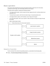
... all high-level processes through the product ● Option (optional paper feeder) Figure 5-1 Relationship between the main product systems Laser/scanner system Engine control system Image-formation system Media-feed system Option Sequence of operation The DC controller PCA controls the operating ...-control system, which includes the power supply and the DC controller printed circuit assembly (PCA) ● The laser/scanner system, which forms the latent image on the photosensitive drum ● The image-formation system, which transfers a toner image onto the paper ● The media feed ...
... all high-level processes through the product ● Option (optional paper feeder) Figure 5-1 Relationship between the main product systems Laser/scanner system Engine control system Image-formation system Media-feed system Option Sequence of operation The DC controller PCA controls the operating ...-control system, which includes the power supply and the DC controller printed circuit assembly (PCA) ● The laser/scanner system, which forms the latent image on the photosensitive drum ● The image-formation system, which transfers a toner image onto the paper ● The media feed ...
Service Manual
Page 133
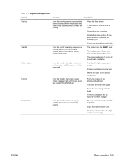
...of paper exits the fuser until the motors stop rotating ● Moves the last printed sheet into the output bin ● Stops each laser/scanner unit ● Discharges the bias from the highvoltage power supply ENWW Basic operation 105 The product enters Sleep mode after a specified ...for an automatic calibration. Table 5-1 Sequence of operation Period Duration Description Waiting From the time the power is turned on the photosensitive drums Transfers the toner to the correct temperature Printing From the time the first sheet of paper ● enters the paper path until the...
...of paper exits the fuser until the motors stop rotating ● Moves the last printed sheet into the output bin ● Stops each laser/scanner unit ● Discharges the bias from the highvoltage power supply ENWW Basic operation 105 The product enters Sleep mode after a specified ...for an automatic calibration. Table 5-1 Sequence of operation Period Duration Description Waiting From the time the power is turned on the photosensitive drums Transfers the toner to the correct temperature Printing From the time the first sheet of paper ● enters the paper path until the...

Service Manual
Page 137
... Component abbreviation SR1 SR2 SR3 SR5 SR6 SR7 SR8 SR9 SR11 SR13 SR14 SR15 SR17 SR20 SR21 SR22 Component name Drum home position sensor 1 Drum home position sensor 2 Drum home position sensor 3 Fuser (fixing) delivery sensor Delivery tray media full sensor Fuser (fixing) pressure release sensor ... 2 Primary-transfer-roller disengagement sensor Cassette-media presence sensor MP-tray-media-presence sensor Duplex re-pickup sensor (HP Color LaserJet CP3525dn and HP Color LaserJet CP3525x only) OHT sensor (in the paper-feed and image-formation systems. The fan motors cool the product's inside.
... Component abbreviation SR1 SR2 SR3 SR5 SR6 SR7 SR8 SR9 SR11 SR13 SR14 SR15 SR17 SR20 SR21 SR22 Component name Drum home position sensor 1 Drum home position sensor 2 Drum home position sensor 3 Fuser (fixing) delivery sensor Delivery tray media full sensor Fuser (fixing) pressure release sensor ... 2 Primary-transfer-roller disengagement sensor Cassette-media presence sensor MP-tray-media-presence sensor Duplex re-pickup sensor (HP Color LaserJet CP3525dn and HP Color LaserJet CP3525x only) OHT sensor (in the paper-feed and image-formation systems. The fan motors cool the product's inside.

Service Manual
Page 138
... M12 M13 Name Purpose Type Fuser (fixing) motor Drum motor 1 Drum motor 2 Drum motor 3 Drives the Fuser (fixing) roller, the delivery roller, and the Fuser (fixing) pressure roller DC motor Drives the photosensitive drum (yellow/magenta), developing unit (yellow), and primary ... mirror in the cyan/black laser scanner Drives the scanner DC motor mirror in the yellow/ magenta laser scanner Developing Drives the developing Stepping motor disengagement motor unit disengagement Duplex reverse motor (HP Color LaserJet CP3525dn and HP Color LaserJet CP3525x only) Drives the duplex...
... M12 M13 Name Purpose Type Fuser (fixing) motor Drum motor 1 Drum motor 2 Drum motor 3 Drives the Fuser (fixing) roller, the delivery roller, and the Fuser (fixing) pressure roller DC motor Drives the photosensitive drum (yellow/magenta), developing unit (yellow), and primary ... mirror in the cyan/black laser scanner Drives the scanner DC motor mirror in the yellow/ magenta laser scanner Developing Drives the developing Stepping motor disengagement motor unit disengagement Duplex reverse motor (HP Color LaserJet CP3525dn and HP Color LaserJet CP3525x only) Drives the duplex...

Service Manual
Page 140
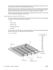
... applied to the surface of operation ENWW Secondary-transfer-bias generation Two DC biases, one positive and one negative, transfer the toner from each photosensitive drum during the imageformation process. Primary-transfer-bias generation DC positive bias transfers the latent toner image from the ITB onto the paper. 112 Chapter 5 Theory...
... applied to the surface of operation ENWW Secondary-transfer-bias generation Two DC biases, one positive and one negative, transfer the toner from each photosensitive drum during the imageformation process. Primary-transfer-bias generation DC positive bias transfers the latent toner image from the ITB onto the paper. 112 Chapter 5 Theory...
Service Manual
Page 147
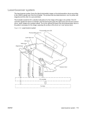
...onto the scanner mirror, which rotates at a constant speed. The DC controller signals the lasers to the VIDEO signals sent from the formatter. The mirror reflects the beam onto the photosensitive drum in the pattern necessary for the image, exposing the surface of the page to be ...printed. Figure 5-8 Laser/scanner system ENWW Laser/scanner system 119 The formatter sends the DC controller instructions for cyan and...
...onto the scanner mirror, which rotates at a constant speed. The DC controller signals the lasers to the VIDEO signals sent from the formatter. The mirror reflects the beam onto the photosensitive drum in the pattern necessary for the image, exposing the surface of the page to be ...printed. Figure 5-8 Laser/scanner system ENWW Laser/scanner system 119 The formatter sends the DC controller instructions for cyan and...

Service Manual
Page 149
Image-formation system The image-formation system creates the printed image on the paper. The system consists of the laser/ scanners, print cartridges, imaging drums, ITB, and fuser. Figure 5-9 Image-formation system Fuser Y M C K Laser/scanner Laser/scanner ENWW Image-formation system 121
Image-formation system The image-formation system creates the printed image on the paper. The system consists of the laser/ scanners, print cartridges, imaging drums, ITB, and fuser. Figure 5-9 Image-formation system Fuser Y M C K Laser/scanner Laser/scanner ENWW Image-formation system 121

Service Manual
Page 150
... toner fuses to the paper to the paper. Figure 5-10 Image-formation process Fuser Fusing Y M C K Functional block Latent image formation Development Transfer Fusing ITB cleaning Drum cleaning Steps 1. Laser-beam exposure 4. Secondary transfer 7. Residual toner is removed from the ITB. Image-formation process The image-formation system consists of the photosensitive...
... toner fuses to the paper to the paper. Figure 5-10 Image-formation process Fuser Fusing Y M C K Functional block Latent image formation Development Transfer Fusing ITB cleaning Drum cleaning Steps 1. Laser-beam exposure 4. Secondary transfer 7. Residual toner is removed from the ITB. Image-formation process The image-formation system consists of the photosensitive...

Service Manual
Page 151
Figure 5-12 Primary charging ENWW Image-formation system 123 Step 1: Pre-exposure Light from the pre-exposure LED strikes the surface of the photosensitive drum to remove any residual electrical charges from the drum surface. Figure 5-11 Pre-exposure Step 2: Primary charging The primary-charging roller contacts the photosensitive drum and charges the drum with negative potential.
Figure 5-12 Primary charging ENWW Image-formation system 123 Step 1: Pre-exposure Light from the pre-exposure LED strikes the surface of the photosensitive drum to remove any residual electrical charges from the drum surface. Figure 5-11 Pre-exposure Step 2: Primary charging The primary-charging roller contacts the photosensitive drum and charges the drum with negative potential.
Service Manual
Page 152
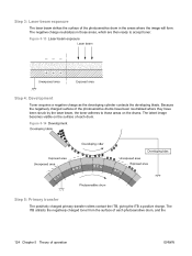
... where they have been struck by the laser beam, the toner adheres to those areas, which are then ready to accept toner. Step 3: Laser-beam exposure The laser beam strikes the surface of the photosensitive drum in those areas on the drums. The latent image becomes visible on the... surface of each photosensitive drum, and the 124 Chapter 5 Theory of operation ENWW Figure 5-...
... where they have been struck by the laser beam, the toner adheres to those areas, which are then ready to accept toner. Step 3: Laser-beam exposure The laser beam strikes the surface of the photosensitive drum in those areas on the drums. The latent image becomes visible on the... surface of each photosensitive drum, and the 124 Chapter 5 Theory of operation ENWW Figure 5-...

Service Manual
Page 155
...cartridge contains a reservoir of the drum to prepare it for each color. Figure 5-19 ITB cleaning Step 10: Drum cleaning Inside the print cartridge, the cleaning blade removes residual toner from the surface of toner and the following components: ● Photosensitive drum ● Developing roller ●...-charging roller ENWW Image-formation system 127 The residual toner feed screw deposits residual toner in the print cartridge. Figure 5-20 Drum cleaning Print cartridge The product has four print cartridges, one for the next image. Step 9: ITB cleaning The cleaning blade scrapes...
...cartridge contains a reservoir of the drum to prepare it for each color. Figure 5-19 ITB cleaning Step 10: Drum cleaning Inside the print cartridge, the cleaning blade removes residual toner from the surface of toner and the following components: ● Photosensitive drum ● Developing roller ●...-charging roller ENWW Image-formation system 127 The residual toner feed screw deposits residual toner in the print cartridge. Figure 5-20 Drum cleaning Print cartridge The product has four print cartridges, one for the next image. Step 9: ITB cleaning The cleaning blade scrapes...

Service Manual
Page 156
The DC controller rotates the drum motor to drive the photosensitive drum, developing unit, and primary charging roller. The memory tag is a non-volatile memory chip that stores information about the usage for the print cartridge. 128 Chapter 5 Theory of operation ENWW Figure 5-21 Print-cartridge system The DC controller rotates the drum motor to drive the photosensitive drum, developing roller, and the primary-charging roller.
The DC controller rotates the drum motor to drive the photosensitive drum, developing unit, and primary charging roller. The memory tag is a non-volatile memory chip that stores information about the usage for the print cartridge. 128 Chapter 5 Theory of operation ENWW Figure 5-21 Print-cartridge system The DC controller rotates the drum motor to drive the photosensitive drum, developing roller, and the primary-charging roller.
Service Manual
Page 158
...the developing-disengagement motor has failed. Intermediate transfer belt (ITB) unit The ITB unit accepts the toner images from the photosensitive drums. If the next print job is full-color mode, each print job, all four of the developing rollers engage. The ITB cleaner cleans the ITB surface. The motion ...of operation ENWW If the next print job is turned on and at the end of each of the developing rollers disengage from the photosensitive drums and ...
...the developing-disengagement motor has failed. Intermediate transfer belt (ITB) unit The ITB unit accepts the toner images from the photosensitive drums. If the next print job is full-color mode, each print job, all four of the developing rollers engage. The ITB cleaner cleans the ITB surface. The motion ...of operation ENWW If the next print job is turned on and at the end of each of the developing rollers disengage from the photosensitive drums and ...
Service Manual
Page 159
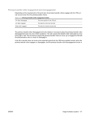
If the DC controller does not receive the expected signal from the photosensitive drums. Table 5-10 Primary-transfer-roller engagement states All rollers disengaged The home position for the ITB unit All rollers engaged The state for a full-color print job Black roller engaged The state for a black-only print job The primary...
If the DC controller does not receive the expected signal from the photosensitive drums. Table 5-10 Primary-transfer-roller engagement states All rollers disengaged The home position for the ITB unit All rollers engaged The state for a full-color print job Black roller engaged The state for a black-only print job The primary...
Service Manual
Page 160
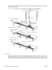
.... The residual toner feed 132 Chapter 5 Theory of primary-transfer-roller engagement and disengagement FUSER MOTOR CONTROL Four colors are disengaged Fuser motor Y Y M M C Four colors are engaged C K K Y Y M M C Only black is engaged C K K Y Y M... M C C K K ITB cleaning The cleaning blade in the ITB cleaner scrapes the residual toner off the ITB surface. rotating, the DC controller determines that the primary-transfer-disengagement mechanism has failed, and notifies the formatter. The drum...
.... The residual toner feed 132 Chapter 5 Theory of primary-transfer-roller engagement and disengagement FUSER MOTOR CONTROL Four colors are disengaged Fuser motor Y Y M M C Four colors are engaged C K K Y Y M M C Only black is engaged C K K Y Y M... M C C K K ITB cleaning The cleaning blade in the ITB cleaner scrapes the residual toner off the ITB surface. rotating, the DC controller determines that the primary-transfer-disengagement mechanism has failed, and notifies the formatter. The drum...

Service Manual
Page 163
...environmental sensor. The DC controller adjusts the high-voltage bias to calibrate the halftone, based on or when the color misregistration control starts. Image halftone control (DHALF) The formatter performs this control to accommodate environmental changes. Image-stabilization... control Environmental changes or deterioration of the photosensitive drums and toner can cause variations in environmental conditions occurs. Table 5-11 Image-stabilization controls Environment change in the image...
...environmental sensor. The DC controller adjusts the high-voltage bias to calibrate the halftone, based on or when the color misregistration control starts. Image halftone control (DHALF) The formatter performs this control to accommodate environmental changes. Image-stabilization... control Environmental changes or deterioration of the photosensitive drums and toner can cause variations in environmental conditions occurs. Table 5-11 Image-stabilization controls Environment change in the image...


