Service Manual
Page 11
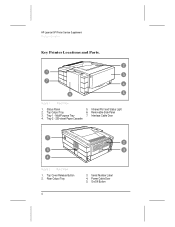
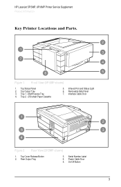
Top Output Tray 6. Rear Output Tray 4 3. MultiPurpose Tray 7. Serial Number Label 4. On/Off Button Tray 1 - Tray 2 - 250-sheet Paper Cassette Figure 2 Rear View 1. Top Cover Release Button 2. Power Cable Door 5. Infrared Port and Status Light 2. Removable Side Panel 3. Figure 1 Front View 1. Status Panel 5. Interface Cable Door 4. HP LaserJet 5P Printer Service Supplement Product Information Key Printer Locations and Parts.
Top Output Tray 6. Rear Output Tray 4 3. MultiPurpose Tray 7. Serial Number Label 4. On/Off Button Tray 1 - Tray 2 - 250-sheet Paper Cassette Figure 2 Rear View 1. Top Cover Release Button 2. Power Cable Door 5. Infrared Port and Status Light 2. Removable Side Panel 3. Figure 1 Front View 1. Status Panel 5. Interface Cable Door 4. HP LaserJet 5P Printer Service Supplement Product Information Key Printer Locations and Parts.
Service Manual
Page 27
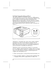
... light is compatible with a wide variety of IrDA-compliant portable devices; HP LaserJet 5P Printer Service Supplement New Product Features To Print Using the Infrared Port The infrared (IR) port on your HP LaserJet 5P or 5MP printer is complete, the status light goes off. 1. Refer to use the... the printer (Figure 8). Just above the port is a status light that is activated. Align your laptop computer (or other portable equipment) that indicates when the port is equipped with the specifications determined by receiving data similarly to a serial port, however, without a cable and ...
... light is compatible with a wide variety of IrDA-compliant portable devices; HP LaserJet 5P Printer Service Supplement New Product Features To Print Using the Infrared Port The infrared (IR) port on your HP LaserJet 5P or 5MP printer is complete, the status light goes off. 1. Refer to use the... the printer (Figure 8). Just above the port is a status light that is activated. Align your laptop computer (or other portable equipment) that indicates when the port is equipped with the specifications determined by receiving data similarly to a serial port, however, without a cable and ...
Service Manual
Page 32
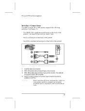
... IEEE-1284 compatible. 4. Figure 11 HP LaserJet 5P/5MP Printer Interface Connections 1. IEEE-1284 parallel cable and large (B-type) printer connector. 3. LocalTalk cable and connectors. 2. IEEE-1284 parallel cable and small (C-type) printer connector. (The cable will be available on host PCs). HP LaserJet 5P Printer Service Supplement New Product Features Interface Connections Your HP LaserJet 5P or 5MP printer supports the following interfaces (see...
... IEEE-1284 compatible. 4. Figure 11 HP LaserJet 5P/5MP Printer Interface Connections 1. IEEE-1284 parallel cable and large (B-type) printer connector. 3. LocalTalk cable and connectors. 2. IEEE-1284 parallel cable and small (C-type) printer connector. (The cable will be available on host PCs). HP LaserJet 5P Printer Service Supplement New Product Features Interface Connections Your HP LaserJet 5P or 5MP printer supports the following interfaces (see...
Service Manual
Page 33
...parallel, infrared, and LocalTalk) when multiple users share the printer. 26 support for "Compatibility Mode" and "Nibble Mode" or "HP Bi-tronics". HP LaserJet 5P Printer Service Supplement New Product Features The Parallel Printer Interfaces These interfaces are compliant with networks, most hardware print ... port on your supplier on the cable. Use a high-quality, shielded IEEE-1284 compliant parallel interface cable to insure best performance and support of up to the computer (bi-directional communication). To use the printer's parallel interface to send status information...
...parallel, infrared, and LocalTalk) when multiple users share the printer. 26 support for "Compatibility Mode" and "Nibble Mode" or "HP Bi-tronics". HP LaserJet 5P Printer Service Supplement New Product Features The Parallel Printer Interfaces These interfaces are compliant with networks, most hardware print ... port on your supplier on the cable. Use a high-quality, shielded IEEE-1284 compliant parallel interface cable to insure best performance and support of up to the computer (bi-directional communication). To use the printer's parallel interface to send status information...
Service Manual
Page 47
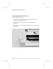
Press the removable side panel release latch shown in Figure 14. 4. Press the Top Cover Release button on the right side of the printer. Figure 14 Left Side Cover Release Latch 40 HP LaserJet 5P Printer Service Supplement Removal and Replacement Removing the Left Side Cover 1. Slide the cover forward and pull straight away from the side of the printer, and open the top cover. 3. Disconnect all I/O cables. 2.
Press the removable side panel release latch shown in Figure 14. 4. Press the Top Cover Release button on the right side of the printer. Figure 14 Left Side Cover Release Latch 40 HP LaserJet 5P Printer Service Supplement Removal and Replacement Removing the Left Side Cover 1. Slide the cover forward and pull straight away from the side of the printer, and open the top cover. 3. Disconnect all I/O cables. 2.
Service Manual
Page 51
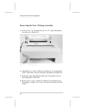
... left corner.) 44 Remove the 5 screws (callout 1 in Figure 19) from the front of the printer chassis and bring them to the plug and pulling straight back. 3. Figure 18 Removing Tray 1. 2. Route the cables through the right side of the pickup assembly. (Two screws are adjacent in Figure 19) by opening... the tray at a 45° angle and pulling up on the tray (Figure 18). Remove Tray 1 by grasping the cables where they attach to the front. 4. HP LaserJet 5P Printer Service Supplement Removal and Replacement Removing the Tray 1 Pickup Assembly 1.
... left corner.) 44 Remove the 5 screws (callout 1 in Figure 19) from the front of the printer chassis and bring them to the plug and pulling straight back. 3. Figure 18 Removing Tray 1. 2. Route the cables through the right side of the pickup assembly. (Two screws are adjacent in Figure 19) by opening... the tray at a 45° angle and pulling up on the tray (Figure 18). Remove Tray 1 by grasping the cables where they attach to the front. 4. HP LaserJet 5P Printer Service Supplement Removal and Replacement Removing the Tray 1 Pickup Assembly 1.
Service Manual
Page 58
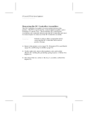
...51 Disconnect the two cables to remove these components before removing the DC Controller will result in Figure 25). 3. The Formatter PCA and Fusing Assemblies are connected directly into the DC Controller and must be removed prior to a plastic base. Remove the printer covers (page 39),...On the right side, remove the machine screw and washer (Figure 25) holding the grounding spring in place. (Callout 1 in printer damage. 1. HP LaserJet 5P Printer Service Supplement Removal and Replacement Removing the DC Controller Assemblies The DC Controller Assembly is mounted to removal of the...
...51 Disconnect the two cables to remove these components before removing the DC Controller will result in Figure 25). 3. The Formatter PCA and Fusing Assemblies are connected directly into the DC Controller and must be removed prior to a plastic base. Remove the printer covers (page 39),...On the right side, remove the machine screw and washer (Figure 25) holding the grounding spring in place. (Callout 1 in printer damage. 1. HP LaserJet 5P Printer Service Supplement Removal and Replacement Removing the DC Controller Assemblies The DC Controller Assembly is mounted to removal of the...
Service Manual
Page 60
...the metal backing plate from the connector no releases are necessary. 53 This cable can easily be broken when separating it can be retained when replacing the DC Controller Board. HP LaserJet 5P Printer Service Supplement Removal and Replacement Note The PS1 Input Sensor Arm may come ...loose and fall out when you remove the DC Controller Assembly. Disconnect Tray 1 Interconnect PCA (callout 2 in Figure 26) and cable 302 (callout 1 in ...
...the metal backing plate from the connector no releases are necessary. 53 This cable can easily be broken when separating it can be retained when replacing the DC Controller Board. HP LaserJet 5P Printer Service Supplement Removal and Replacement Note The PS1 Input Sensor Arm may come ...loose and fall out when you remove the DC Controller Assembly. Disconnect Tray 1 Interconnect PCA (callout 2 in Figure 26) and cable 302 (callout 1 in ...
Service Manual
Page 63
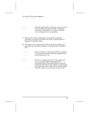
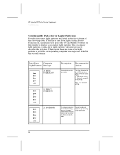
... of the following table. Reduce the complexity of improper signal protocols. Reseat the cable and make sure you are listed in the second column. HP LaserJet 5P Printer Service Supplement Troubleshooting Continuable Data Error Light Patterns Possible data error light patterns are using... a high-quality cable 56 Add optional memory. 3. Where more precisely describe the problem. Turn ...
... of the following table. Reduce the complexity of improper signal protocols. Reseat the cable and make sure you are listed in the second column. HP LaserJet 5P Printer Service Supplement Troubleshooting Continuable Data Error Light Patterns Possible data error light patterns are using... a high-quality cable 56 Add optional memory. 3. Where more precisely describe the problem. Turn ...
Service Manual
Page 86
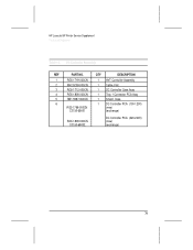
HP LaserJet 5P Printer Service Supplement Parts and Diagrams Table 16. QTY DESCRIPTION 1 RG5-1719-000CN 1 HVT Controller Assembly 2 RH2-5259-000CN 1 Cable, Flat 3 RG5-1712-000CN 1 DC Controller Case Assy 4 RG5-1808-000CN 1 Tray 1 Connector PCA Assy 5 RB1-5987-000CN 1 Shield, Case 6 RG5-1798-000CN C3150-69001 1 DC Controller PCA (100-120V) (new) (exchange) RG5-1809-000CN C3150-69002 DC Controller PCA (220-240V) (new) (exchange) 79 DC Controller Assembly REF PART NO.
HP LaserJet 5P Printer Service Supplement Parts and Diagrams Table 16. QTY DESCRIPTION 1 RG5-1719-000CN 1 HVT Controller Assembly 2 RH2-5259-000CN 1 Cable, Flat 3 RG5-1712-000CN 1 DC Controller Case Assy 4 RG5-1808-000CN 1 Tray 1 Connector PCA Assy 5 RB1-5987-000CN 1 Shield, Case 6 RG5-1798-000CN C3150-69001 1 DC Controller PCA (100-120V) (new) (exchange) RG5-1809-000CN C3150-69002 DC Controller PCA (220-240V) (new) (exchange) 79 DC Controller Assembly REF PART NO.
Service Manual
Page 90
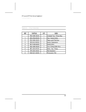
Tray 1 Assembly REF PART NO. HP LaserJet 5P Printer Service Supplement Parts and Diagrams Table 18. QTY DESC RG5-1695-000CN 1 Complete Tray 1 Pickup Assy 1 RG5-1804-000CN 1 Tray 1 Sensor Cable 2 RG5-1694-000CN 1 Paper guide Plate Assy 3 RS5-2415-000CN 1 Spring, Compression 4 RH7-1258-000CN 1 Solenoid SL2 5 RG5-1693-000CN 1 Tray 1 Pickup Roller Assy 6 RB1-2205-000CN 1 Roller, Tray 1 Pickup 7 RF5-0343-000CN 1 Pad, Separation 8 WG8-5210-000CN 1 Photosensor PS5 83
Tray 1 Assembly REF PART NO. HP LaserJet 5P Printer Service Supplement Parts and Diagrams Table 18. QTY DESC RG5-1695-000CN 1 Complete Tray 1 Pickup Assy 1 RG5-1804-000CN 1 Tray 1 Sensor Cable 2 RG5-1694-000CN 1 Paper guide Plate Assy 3 RS5-2415-000CN 1 Spring, Compression 4 RH7-1258-000CN 1 Solenoid SL2 5 RG5-1693-000CN 1 Tray 1 Pickup Roller Assy 6 RB1-2205-000CN 1 Roller, Tray 1 Pickup 7 RF5-0343-000CN 1 Pad, Separation 8 WG8-5210-000CN 1 Photosensor PS5 83
Service Manual
Page 93
... A to B-C2951A 3 Meter A to C-C2946A 10 Meter A to C-C2947A IEEE-1284-compliant cables, where: A=host computer connector (A-type) B=large printer connector (B-type) C=small printer connector (C-type) LocalTalk Network cable for Macintosh 92215N Connect to the HP LaserJet 5P printer, for Macintosh, Windows 3.1 and 3.11, and "HP LaserJet 5MP Macintosh Notes" (factory-installed in this appendix. 86 Memory upgrades 1 MByte...
... A to B-C2951A 3 Meter A to C-C2946A 10 Meter A to C-C2947A IEEE-1284-compliant cables, where: A=host computer connector (A-type) B=large printer connector (B-type) C=small printer connector (C-type) LocalTalk Network cable for Macintosh 92215N Connect to the HP LaserJet 5P printer, for Macintosh, Windows 3.1 and 3.11, and "HP LaserJet 5MP Macintosh Notes" (factory-installed in this appendix. 86 Memory upgrades 1 MByte...
Service Manual
Page 94
...57 A accessories 86 automatic I/O switching 26 B bi-directional communication 26 books available 8 -9 buttons GO 10 power 4 RESET 10 status panel 10 C cables IEEE-1284 compliant 26 clearing memory with RESET 10 cold reset 30 connections network 26 consumables life 36 ordering 69 D data light 12 DC controller... to 11 demo page 10, 30, 33 diagnostic 30 diagrams covers and doors 70 DC controller 78 fusing assembly 84 internal components 72, 74, 76 printer parts 4 tray 1 assembly 82 tray 2 assembly 80 wiring 67 DMO 69 documentation 8 -9 drivers 9 E Economode 3 erasing memory with RESET 11 error ...
...57 A accessories 86 automatic I/O switching 26 B bi-directional communication 26 books available 8 -9 buttons GO 10 power 4 RESET 10 status panel 10 C cables IEEE-1284 compliant 26 clearing memory with RESET 10 cold reset 30 connections network 26 consumables life 36 ordering 69 D data light 12 DC controller... to 11 demo page 10, 30, 33 diagnostic 30 diagrams covers and doors 70 DC controller 78 fusing assembly 84 internal components 72, 74, 76 printer parts 4 tray 1 assembly 82 tray 2 assembly 80 wiring 67 DMO 69 documentation 8 -9 drivers 9 E Economode 3 erasing memory with RESET 11 error ...
Service Manual
Page 95
..., 33 panel See status panel paper jams 11 movement, overview (theory) 16 path 16 -17 size 3 specifications 8 -9 trays 3, 4, 86 paper-out flag 43 parallel cable 26 parallel interface 3 parallel ports 25 parts ordering 68, 86 Parts Center Europe (PCE) 68 parts and diagrams 68 -85 parts, location 4, 17 PCE 68... 30 -35 port infrared 19 ports 25 PostScript, SIMM removal 39 power door removal and replacement 39 power switch 4 print speed 3 print spoolers 26 printer diagram 4 lights 11 parts diagram 4 serial number 5 printer configuration 30 printer languages 3 printer settings returning to defaults 11
..., 33 panel See status panel paper jams 11 movement, overview (theory) 16 path 16 -17 size 3 specifications 8 -9 trays 3, 4, 86 paper-out flag 43 parallel cable 26 parallel interface 3 parallel ports 25 parts ordering 68, 86 Parts Center Europe (PCE) 68 parts and diagrams 68 -85 parts, location 4, 17 PCE 68... 30 -35 port infrared 19 ports 25 PostScript, SIMM removal 39 power door removal and replacement 39 power switch 4 print speed 3 print spoolers 26 printer diagram 4 lights 11 parts diagram 4 serial number 5 printer configuration 30 printer languages 3 printer settings returning to defaults 11
Service Manual
Page 106
Tray 1 - Serial Number Label 4. Tray 2 - 250-sheet Paper Cassette 5. Figure 1 Front View (5P/5MP shown) 1. Infrared Port and Status Light 6. Power Cable Door 5. Interface Cable Door Figure 2 Rear View (5P/5MP shown) 1. On/Off Button 3 HP LaserJet 5P/5MP, 6P/6MP Printer Service Supplement Product Information Key Printer Locations and Parts. Top Status Panel 2. Top Output Tray 3. MultiPurpose Tray 4. Removable Side Panel 7. Top Cover Release Button 2. Rear Output Tray 3.
Tray 1 - Serial Number Label 4. Tray 2 - 250-sheet Paper Cassette 5. Figure 1 Front View (5P/5MP shown) 1. Infrared Port and Status Light 6. Power Cable Door 5. Interface Cable Door Figure 2 Rear View (5P/5MP shown) 1. On/Off Button 3 HP LaserJet 5P/5MP, 6P/6MP Printer Service Supplement Product Information Key Printer Locations and Parts. Top Status Panel 2. Top Output Tray 3. MultiPurpose Tray 4. Removable Side Panel 7. Top Cover Release Button 2. Rear Output Tray 3.
Service Manual
Page 122
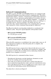
...port's speed depends on . The data flow is complete, the status light goes off. HP LaserJet 5P/5MP, 6P/6MP Printer Service Supplement New Product Features Infrared Communication The HP LaserJet 5P/5MP and 6P/6MP printers are read-only; A primary device -- Secondary devices are equipped with an Infrared Datalink Association...print data between a wide variety of reading and writing data to another primary device or writing to a serial port, but without a cable. If the connection is broken or when the print job is shown in each device for validity, and a response is contained in ...
...port's speed depends on . The data flow is complete, the status light goes off. HP LaserJet 5P/5MP, 6P/6MP Printer Service Supplement New Product Features Infrared Communication The HP LaserJet 5P/5MP and 6P/6MP printers are read-only; A primary device -- Secondary devices are equipped with an Infrared Datalink Association...print data between a wide variety of reading and writing data to another primary device or writing to a serial port, but without a cable. If the connection is broken or when the print job is shown in each device for validity, and a response is contained in ...
Service Manual
Page 130
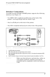
... one small C-type. • One LocalTalk port at the back of the printer. • One IrDA-compliant infrared port at the front of the printer. Figure 12 HP LaserJet 5P/5MP, 6P/6MP Printer Interface Connections 1. IEEE-1284 parallel cable and small (C-type) printer connector. (The cable will be available on host PCs). Caution Make sure that all power...
... one small C-type. • One LocalTalk port at the back of the printer. • One IrDA-compliant infrared port at the front of the printer. Figure 12 HP LaserJet 5P/5MP, 6P/6MP Printer Interface Connections 1. IEEE-1284 parallel cable and small (C-type) printer connector. (The cable will be available on host PCs). Caution Make sure that all power...
Service Manual
Page 131
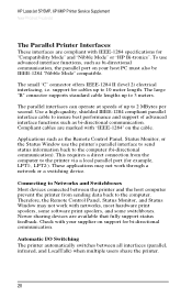
... data back to the computer (bi-directional communication). HP LaserJet 5P/5MP, 6P/6MP Printer Service Supplement New Product Features The Parallel Printer Interfaces These interfaces are compliant with "IEEE-1284" on the cable. support for cables up to the printer via a local parallel port (for example, LPT1:, LPT2:). Compliant cables are available that fully support status feedback. These...
... data back to the computer (bi-directional communication). HP LaserJet 5P/5MP, 6P/6MP Printer Service Supplement New Product Features The Parallel Printer Interfaces These interfaces are compliant with "IEEE-1284" on the cable. support for cables up to the printer via a local parallel port (for example, LPT1:, LPT2:). Compliant cables are available that fully support status feedback. These...
Service Manual
Page 148
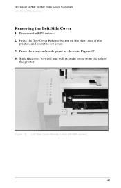
Disconnect all I/O cables. 2. Slide the cover forward and pull straight away from the side of the printer, and open the top cover. 3. Figure 17 Left Side Cover Release Latch (5P/5MP shown) 45 Press the Top Cover Release button on the right side of the printer. HP LaserJet 5P/5MP, 6P/6MP Printer Service Supplement Removal and Replacement Removing the Left Side Cover 1. Press the removable side panel as shown in Figure 17. 4.
Disconnect all I/O cables. 2. Slide the cover forward and pull straight away from the side of the printer, and open the top cover. 3. Figure 17 Left Side Cover Release Latch (5P/5MP shown) 45 Press the Top Cover Release button on the right side of the printer. HP LaserJet 5P/5MP, 6P/6MP Printer Service Supplement Removal and Replacement Removing the Left Side Cover 1. Press the removable side panel as shown in Figure 17. 4.
Service Manual
Page 152
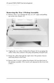
... 2 in the lower left corner.) 49 Figure 21 Removing Tray 1. 2. HP LaserJet 5P/5MP, 6P/6MP Printer Service Supplement Removal and Replacement Removing the Tray 1 Pickup Assembly 1. Remove Tray 1 by grasping the cables where they attach to the front. 4. Route the cables through the right side of the pickup assembly. (Two screws are adjacent in Figure...
... 2 in the lower left corner.) 49 Figure 21 Removing Tray 1. 2. HP LaserJet 5P/5MP, 6P/6MP Printer Service Supplement Removal and Replacement Removing the Tray 1 Pickup Assembly 1. Remove Tray 1 by grasping the cables where they attach to the front. 4. Route the cables through the right side of the pickup assembly. (Two screws are adjacent in Figure...


