
HP Color LaserJet 8550, 8550N, 8550DN, 8550GN, 8550MFP Printer - User Guide
Page 136
... then on to reset the printer. If the condition persists, contact a local authorized HP dealer or service representative for service. 59.X MOTOR ERROR CYCLE POWER Indicates that the main printer motor is out of the cooling fans has failed. X = Fan Type 1 = Rear Output Fan (Motor 1) 2 = Rear Input Fan (Motor 2) 3 = Left Output Fan (Motor 3) Turn the printer off and on configuring input...
... then on to reset the printer. If the condition persists, contact a local authorized HP dealer or service representative for service. 59.X MOTOR ERROR CYCLE POWER Indicates that the main printer motor is out of the cooling fans has failed. X = Fan Type 1 = Rear Output Fan (Motor 1) 2 = Rear Input Fan (Motor 2) 3 = Left Output Fan (Motor 3) Turn the printer off and on configuring input...

Service Manual
Page 13
... the electrical unit cover 370 Figure 264. Accessory power supply 374 Figure 269. Power supply cooling fan 375 Figure 270. Removing the ADF 379 Figure 274. Securing the metal cable clamp to the mirror 1 mount (rear view 351 Figure 236. Flexible cable warning label 353 Figure 239. Detaching the scanning lamp 359...
... the electrical unit cover 370 Figure 264. Accessory power supply 374 Figure 269. Power supply cooling fan 375 Figure 270. Removing the ADF 379 Figure 274. Securing the metal cable clamp to the mirror 1 mount (rear view 351 Figure 236. Flexible cable warning label 353 Figure 239. Detaching the scanning lamp 359...

Service Manual
Page 28
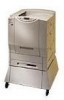
Copy module front left 1 Copyboard cover 2 Copyboard glass 3 Control panel 4 Power supply cooling fan air inlet 12 2 32 42 Figure 2. Copy module front right 1 Control key switch 2 Power supply cord connector 3 Rear power switch 4 Printer power cord connector 26 Chapter 1 - Overview 12 42 2 32 Figure 1. Product information EN
Copy module front left 1 Copyboard cover 2 Copyboard glass 3 Control panel 4 Power supply cooling fan air inlet 12 2 32 42 Figure 2. Copy module front right 1 Control key switch 2 Power supply cord connector 3 Rear power switch 4 Printer power cord connector 26 Chapter 1 - Overview 12 42 2 32 Figure 1. Product information EN

Service Manual
Page 334
...30 minutes after turning off the control panel power soft switch (to the right of the copy module control panel) or turning off , the fans continue to operate to cool the printer (to the right of the scanner motor. One is turned off the control panel soft switch and the copy module... varistor, as it on a table when servicing to avoid personal injury or damage to the right side of the copy module rear), and then remove the fusing assembly of the printer unit. Service the copy module as it from its parts removed, unless otherwise instructed. Removal is mounted on the stand. l ...
...30 minutes after turning off the control panel power soft switch (to the right of the copy module control panel) or turning off , the fans continue to operate to cool the printer (to the right of the scanner motor. One is turned off the control panel soft switch and the copy module... varistor, as it on a table when servicing to avoid personal injury or damage to the right side of the copy module rear), and then remove the fusing assembly of the printer unit. Service the copy module as it from its parts removed, unless otherwise instructed. Removal is mounted on the stand. l ...

Service Manual
Page 377
EN Copy module 375 Removing the power supply cooling fan (FM4) 1 Remove the copy module upper rear cover, upper left cover, and rear cover, in that air is toward the inside (so that order. 2 Disconnect the connector, and remove two screws (callout 1). 3 Detach the fan. 21 Figure 269. CAUTION Power supply cooling fan When mounting the fan (FM4), be sure that the arrow on the fan is blown toward the inside ).
EN Copy module 375 Removing the power supply cooling fan (FM4) 1 Remove the copy module upper rear cover, upper left cover, and rear cover, in that air is toward the inside (so that order. 2 Disconnect the connector, and remove two screws (callout 1). 3 Detach the fan. 21 Figure 269. CAUTION Power supply cooling fan When mounting the fan (FM4), be sure that the arrow on the fan is blown toward the inside ).

Service Manual
Page 679
... unit Control panel PCB assembly1 Lock pin assembly Paper feed motor assembly Separation roller assembly Caster, unit Lifter drive assembly Side guide plate, rear Paper separation assembly Upper cover assembly Lower paper guide assembly Right paper delivery assembly Control inverter PCB assembly (See note 3) Power cord ... (J2022) Power cord (100/127 V P2) Switching regulator PCB unit Function switch PCB unit Motor, dc 23 V (M1 J12) Motor, stepping (PM1 J302) Fan (FM4 J2031) Motor, dc 24 V (M3 J7) ECO-O board PCB unit Lamp, fluorescent (LA1) Figure Key 457 - 423 15 429 - 423 16 439...
... unit Control panel PCB assembly1 Lock pin assembly Paper feed motor assembly Separation roller assembly Caster, unit Lifter drive assembly Side guide plate, rear Paper separation assembly Upper cover assembly Lower paper guide assembly Right paper delivery assembly Control inverter PCB assembly (See note 3) Power cord ... (J2022) Power cord (100/127 V P2) Switching regulator PCB unit Function switch PCB unit Motor, dc 23 V (M1 J12) Motor, stepping (PM1 J302) Fan (FM4 J2031) Motor, dc 24 V (M3 J7) ECO-O board PCB unit Lamp, fluorescent (LA1) Figure Key 457 - 423 15 429 - 423 16 439...

Service Manual
Page 719
...power, troubleshooting 520 diagrams 26 downloading, preparing for 137 electrical tray assembly 578 environment, operating 25, 462 exposure system 178, 188, 189 fan 234 features 23, 51 functions 51, 178 height, troubleshooting 471 horizontal registration, adjusting 124 image faults, troubleshooting 491 image processing system 200 ... input (HCI), removing 435 lower front (copy module) 333, 334 modified top, part numbers 119 part numbers 685 pulley, removing 442 rear (copy module) 333, 336 rear (HCI) 434, 436 upper (ADF) 377, 614 upper front (copy module) 333, 337 upper left (copy module) 333, 335...
...power, troubleshooting 520 diagrams 26 downloading, preparing for 137 electrical tray assembly 578 environment, operating 25, 462 exposure system 178, 188, 189 fan 234 features 23, 51 functions 51, 178 height, troubleshooting 471 horizontal registration, adjusting 124 image faults, troubleshooting 491 image processing system 200 ... input (HCI), removing 435 lower front (copy module) 333, 334 modified top, part numbers 119 part numbers 685 pulley, removing 442 rear (copy module) 333, 336 rear (HCI) 434, 436 upper (ADF) 377, 614 upper front (copy module) 333, 337 upper left (copy module) 333, 335...

Service Manual
Page 732
... 32 power cord terminal assembly diagrams 569, 570 part numbers 571 power cords part numbers 697 printer connector 26 supply connector 26 power plug 177, 462 Power Rating Label 457 power receptacle, high-...troubleshooting 509, 541 voltage 235 power supply cord connector diagrams 26 power switches control panel 50 rear, locating 26 using 177 power, feeding measuring 154 power, troubleshooting ac 519 DC 520 ...no power 458, 541 powering off automatic 55 copier 177 copy module 137 fans 332 overcurrent protection 235 precautions 332 scanning lamp 194 settings 55 troubleshooting 457 powering on ...
... 32 power cord terminal assembly diagrams 569, 570 part numbers 571 power cords part numbers 697 printer connector 26 supply connector 26 power plug 177, 462 Power Rating Label 457 power receptacle, high-...troubleshooting 509, 541 voltage 235 power supply cord connector diagrams 26 power switches control panel 50 rear, locating 26 using 177 power, feeding measuring 154 power, troubleshooting ac 519 DC 520 ...no power 458, 541 powering off automatic 55 copier 177 copy module 137 fans 332 overcurrent protection 235 precautions 332 scanning lamp 194 settings 55 troubleshooting 457 powering on ...

Service Manual
Page 734
... 414, 416 delivery/reversing roller 407 DIMMs 340 driver PCB, scanner motor 339 ECO-2 PCB 371 fans 346, 375 feed roller 399 feeder motor 387, 452 feeding belt 431 flexible cable 353 front cover...365 lifter motor 452 lifter wire 442 lower front cover (copy module) 334 motors (ADF) 387 non-HP components 457 pick-up motor 452, 453 pick-up roller 396, 440 pick-up unit (HCI) 437... supply, copy module 373 power supply, high-capacity input (HCI) 454 pulley cover 442 rear cover (copy module) 336 rear cover (HCI) 436 registration roller 402 reversing guide 419 scanner motor 338 scanning lamp 357 ...
... 414, 416 delivery/reversing roller 407 DIMMs 340 driver PCB, scanner motor 339 ECO-2 PCB 371 fans 346, 375 feed roller 399 feeder motor 387, 452 feeding belt 431 flexible cable 353 front cover...365 lifter motor 452 lifter wire 442 lower front cover (copy module) 334 motors (ADF) 387 non-HP components 457 pick-up motor 452, 453 pick-up roller 396, 440 pick-up unit (HCI) 437... supply, copy module 373 power supply, high-capacity input (HCI) 454 pulley cover 442 rear cover (copy module) 336 rear cover (HCI) 436 registration roller 402 reversing guide 419 scanner motor 338 scanning lamp 357 ...

