
Service Manual
Page 7
... PCA 6-31 Main Gear Assembly 6-35 Pickup Gear Assembly 6-37 Tray 1 Pickup Solenoid 6-39 Fan 6-40 Formatter Assembly 6-41 Tray 1 Roller 6-42 Tray 2 Roller 6-43 Paper Feed Roller Assembly 6-44 DC Controller Board and Power Supply 6-47 Paper Feed Belt Assembly 6-51 Tray 1 Shaft 6-53 Tray 2 Shaft 6-55 Tray... Detect Sensor 6-60 Face Down Bin Full Sensor 6-61 Power Connection 6-63 Registration Assembly 6-64 Upper Delivery Assembly 6-66 Delivery Roller Removal 6-68 Laser Scanner Assembly 6-70 Main Motor 6-71 Toner Cartridge Guides 6-72 Power Inlet Assembly 6-73 4 Contents EN
... PCA 6-31 Main Gear Assembly 6-35 Pickup Gear Assembly 6-37 Tray 1 Pickup Solenoid 6-39 Fan 6-40 Formatter Assembly 6-41 Tray 1 Roller 6-42 Tray 2 Roller 6-43 Paper Feed Roller Assembly 6-44 DC Controller Board and Power Supply 6-47 Paper Feed Belt Assembly 6-51 Tray 1 Shaft 6-53 Tray 2 Shaft 6-55 Tray... Detect Sensor 6-60 Face Down Bin Full Sensor 6-61 Power Connection 6-63 Registration Assembly 6-64 Upper Delivery Assembly 6-66 Delivery Roller Removal 6-68 Laser Scanner Assembly 6-70 Main Motor 6-71 Toner Cartridge Guides 6-72 Power Inlet Assembly 6-73 4 Contents EN

Service Manual
Page 8
...76 Left Front Corner Cover Installation 6-77 Paper Size Spring Assembly 6-78 D-roller and Feed Roller 6-79 Gear Assembly and PCA 6-81 Power Connector 6-82 Separation Roller 6-83 7 Troubleshooting Overview 7-1 Troubleshooting Process 7-2 Troubleshooting Process Flow 7-4 Troubleshooting ...the Printing System 7-6 Preliminary Operating Checks 7-6 Power On 7-7 Display 7-11 Event Log 7-12 Printer Messages 7-16 General Paper Path...
...76 Left Front Corner Cover Installation 6-77 Paper Size Spring Assembly 6-78 D-roller and Feed Roller 6-79 Gear Assembly and PCA 6-81 Power Connector 6-82 Separation Roller 6-83 7 Troubleshooting Overview 7-1 Troubleshooting Process 7-2 Troubleshooting Process Flow 7-4 Troubleshooting ...the Printing System 7-6 Preliminary Operating Checks 7-6 Power On 7-7 Display 7-11 Event Log 7-12 Printer Messages 7-16 General Paper Path...

Service Manual
Page 35
...product qualifies for energy efficiency. 1-26 Printer Description EN ENERGY STAR is a U.S. Energy Consumption This HP LaserJet printer design reduces: Energy usage drops to encourage the development of energy-efficient office products. The printer design eliminates: Ozone Production The printer does not use high-voltage corona wires ... manner. and Japan). As an ENERGY STAR partner, Hewlett-Packard Company has determined that this printer uses charging rollers in the toner cartridge and in the electrophotographic process and therefore generates no appreciable ozone gas (O3).
...product qualifies for energy efficiency. 1-26 Printer Description EN ENERGY STAR is a U.S. Energy Consumption This HP LaserJet printer design reduces: Energy usage drops to encourage the development of energy-efficient office products. The printer design eliminates: Ozone Production The printer does not use high-voltage corona wires ... manner. and Japan). As an ENERGY STAR partner, Hewlett-Packard Company has determined that this printer uses charging rollers in the toner cartridge and in the electrophotographic process and therefore generates no appreciable ozone gas (O3).

Service Manual
Page 87
... Table 4-1. It may be hot. WARNING! Before you change the Toner Cartridge (run a cleaning page). Figure 4-1 Location of the Transfer Roller - Do Not Touch! 4-2 Printer Maintenance EN Do not touch the transfer roller. Hot water sets toner into fabric. Clean the inside parts as indicated in cold water. Observe the warning and caution...
... Table 4-1. It may be hot. WARNING! Before you change the Toner Cartridge (run a cleaning page). Figure 4-1 Location of the Transfer Roller - Do Not Touch! 4-2 Printer Maintenance EN Do not touch the transfer roller. Hot water sets toner into fabric. Clean the inside parts as indicated in cold water. Observe the warning and caution...

Service Manual
Page 88
... dust, spilled toner, and paper particles from the paper path area, the registration roller, and the Toner Cartridge cavity. Paper Pickup, Feed, and Use a water-dampened, lint-free cloth. Fuser Use a water-dampened, lint-free cloth. Cleaning the Printer Component Cleaning Method / Notes Outside Covers Use a water-dampened cloth. DO NOT TOUCH...
... dust, spilled toner, and paper particles from the paper path area, the registration roller, and the Toner Cartridge cavity. Paper Pickup, Feed, and Use a water-dampened, lint-free cloth. Fuser Use a water-dampened, lint-free cloth. Cleaning the Printer Component Cleaning Method / Notes Outside Covers Use a water-dampened cloth. DO NOT TOUCH...

Service Manual
Page 89
... Press [Item] until CREATE CLEANING PAGE appears. 3 Press [Select] to create the cleaning page. 4 Follow the instructions on the rollers and guides inside the printer, shiny black spots will appear on the black strip, create a cleaning page again. If white spots appear on the page's black ... unless it is replaced. Do not touch the Transfer Roller with the damp cloth or with cold water. When toner has been cleaned from inside the printer. To ensure good print quality with a micro-fine particle filter. 4-4 Printer Maintenance EN The pages that print immediately after a paper...
... Press [Item] until CREATE CLEANING PAGE appears. 3 Press [Select] to create the cleaning page. 4 Follow the instructions on the rollers and guides inside the printer, shiny black spots will appear on the black strip, create a cleaning page again. If white spots appear on the page's black ... unless it is replaced. Do not touch the Transfer Roller with the damp cloth or with cold water. When toner has been cleaned from inside the printer. To ensure good print quality with a micro-fine particle filter. 4-4 Printer Maintenance EN The pages that print immediately after a paper...
Service Manual
Page 90
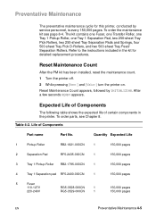
... for detailed replacement procedures. Refer to the instructions included in the printer. Life of certain components in the kit for this printer, conducted by INITIALIZING. To order parts, see page 8-4. To order the maintenance kit see Chapter 8. Quantity Expected Life 1 Pickup Roller RB2-1821-000CN 1 150,000 pages 2 Separation Pad RF5-2435-000CN...
... for detailed replacement procedures. Refer to the instructions included in the printer. Life of certain components in the kit for this printer, conducted by INITIALIZING. To order parts, see page 8-4. To order the maintenance kit see Chapter 8. Quantity Expected Life 1 Pickup Roller RB2-1821-000CN 1 150,000 pages 2 Separation Pad RF5-2435-000CN...

Service Manual
Page 91
Table 4-2. Life of Components (continued) Part name Part No. 6 Transfer Charging RG5-3579-000CN Roller 7 Exhaust Fan RH7-1354-000CN Quantity Expected Life 1 150,000 pages 1 25,000 hours 4-6 Printer Maintenance EN
Table 4-2. Life of Components (continued) Part name Part No. 6 Transfer Charging RG5-3579-000CN Roller 7 Exhaust Fan RH7-1354-000CN Quantity Expected Life 1 150,000 pages 1 25,000 hours 4-6 Printer Maintenance EN

Service Manual
Page 96
... it is abnormal, the CPU identifies the fusing roller heater error, turns the relay (RL1) off and interrupt the power to the fusing roller heater. The circuit operates as follows. EN Power Supply System 5-5 The printer has the following three protection functions to the fusing... heather regardless of the fusing roller heater. Overcurrent Overvoltage Protection This circuit located on ...
... it is abnormal, the CPU identifies the fusing roller heater error, turns the relay (RL1) off and interrupt the power to the fusing roller heater. The circuit operates as follows. EN Power Supply System 5-5 The printer has the following three protection functions to the fusing... heather regardless of the fusing roller heater. Overcurrent Overvoltage Protection This circuit located on ...

Service Manual
Page 97
High Voltage Power Distribution Figure 5-3 High Voltage Power Supply Circuit In response to the instructions from the Formatter PCA, this circuit applies the superimposed voltage of DC voltage and AC voltage to the primary charging roller and developing cylinder, and a positive or negative DC voltage to adjust the image density. 5-6 Functional Information EN According to the image density information sent from the microprocessor (CPU: IC301) on the DC controller, this circuit varies the primary DC bias and developing DC bias to the transfer charging roller.
High Voltage Power Distribution Figure 5-3 High Voltage Power Supply Circuit In response to the instructions from the Formatter PCA, this circuit applies the superimposed voltage of DC voltage and AC voltage to the primary charging roller and developing cylinder, and a positive or negative DC voltage to adjust the image density. 5-6 Functional Information EN According to the image density information sent from the microprocessor (CPU: IC301) on the DC controller, this circuit varies the primary DC bias and developing DC bias to the transfer charging roller.

Service Manual
Page 102
... fixing unit warms up sufficiently, it makes pin 99 (/HALFFAN) "H" to set the fan drive voltage (FANON) to the voltage level to the target fixing roller temperature when the CPU receives the /PRNT signal from the video controller PCA. The fan motor is run the fan motor at half speed. When... the printer turns on, the CPU (IC301) on the DC controller PCA makes pin 99 (/HALFFAN) "H" and runs the fan motor half a turn. The Scanner Motor is...
... fixing unit warms up sufficiently, it makes pin 99 (/HALFFAN) "H" to set the fan drive voltage (FANON) to the voltage level to the target fixing roller temperature when the CPU receives the /PRNT signal from the video controller PCA. The fan motor is run the fan motor at half speed. When... the printer turns on, the CPU (IC301) on the DC controller PCA makes pin 99 (/HALFFAN) "H" and runs the fan motor half a turn. The Scanner Motor is...

Service Manual
Page 109
...3. Image Formation System The image formation system is uniformed by the transfer charging roller. The potential on the drum with the cleaning blade. The laser beam modulated by the video signal is scraped down with the laser diode. If the toner in the cartridge becomes lower than the specified level ...or if there is no cartridge in the printer, it drives the main motor to form ...
...3. Image Formation System The image formation system is uniformed by the transfer charging roller. The potential on the drum with the cleaning blade. The laser beam modulated by the video signal is scraped down with the laser diode. If the toner in the cartridge becomes lower than the specified level ...or if there is no cartridge in the printer, it drives the main motor to form ...

Service Manual
Page 111
The printer also has a new cartridge drive system that wear, degrade, or are consumed in the replaceable Toner Cartridge eliminates the need for a service call when replacement ... Image Formation system is required. Including these components that minimizes banding, with more constant paper speed. The Toner Cartridge contains the photosensitive drum, primary charging roller, developing station, toner cavity, and cleaning station. The Toner Cartridge is the "heart" of the process.
The printer also has a new cartridge drive system that wear, degrade, or are consumed in the replaceable Toner Cartridge eliminates the need for a service call when replacement ... Image Formation system is required. Including these components that minimizes banding, with more constant paper speed. The Toner Cartridge contains the photosensitive drum, primary charging roller, developing station, toner cavity, and cleaning station. The Toner Cartridge is the "heart" of the process.

Service Manual
Page 114
... Image Formation System 5-23 Conditioning the Drum After the drum is coated with conductive rubber with the primary charging roller. The amount of the drum with an AC bias applied to erase any residual charges and maintain a constant drum surface to create a uniform negative potential ... of DC voltage is modified by the print density setting. This process consists of applying a uniform negative charge on the drum surface. The primary charging roller is cleaned, it must be conditioned.
... Image Formation System 5-23 Conditioning the Drum After the drum is coated with conductive rubber with the primary charging roller. The amount of the drum with an AC bias applied to erase any residual charges and maintain a constant drum surface to create a uniform negative potential ... of DC voltage is modified by the print density setting. This process consists of applying a uniform negative charge on the drum surface. The primary charging roller is cleaned, it must be conditioned.

Service Manual
Page 117
.... After separation, the drum is transferred to the page. The small diameter of the drum, combined with the stiffness of the paper by the transfer roller causes the negatively charged toner on the drum surface is cleaned and conditioned for the next image. Transferring the Image During the transferring process the...
.... After separation, the drum is transferred to the page. The small diameter of the drum, combined with the stiffness of the paper by the transfer roller causes the negatively charged toner on the drum surface is cleaned and conditioned for the next image. Transferring the Image During the transferring process the...

Service Manual
Page 118
... Fusing/Variable Fusing Temperature During the fusing process, the toner is fused into the paper. The paper passes between a heated fusing roller and a soft pressure roller. If the fusing system exceeds 464° F (240° C), the thermal fuse will open, cutting off power to the...FUSER ERROR). If the fusing system overheats (about 446° F/230° C), a relay opens, interrupting power to the Fuser. The fusing roller contains a ceramic heating element that is monitored by heat and pressure to produce a permanent image. The DC Controller Board maintains a variable fuser ...
... Fusing/Variable Fusing Temperature During the fusing process, the toner is fused into the paper. The paper passes between a heated fusing roller and a soft pressure roller. If the fusing system exceeds 464° F (240° C), the thermal fuse will open, cutting off power to the...FUSER ERROR). If the fusing system overheats (about 446° F/230° C), a relay opens, interrupting power to the Fuser. The fusing roller contains a ceramic heating element that is monitored by heat and pressure to produce a permanent image. The DC Controller Board maintains a variable fuser ...

Service Manual
Page 120
...the presence of Tray 2 installed in the printer are detected by four switches (SW403, SW404, SW405, and SW406) on while the main motor (M1) is rotating. The paper in Tray 2 is detected by the Tray 1 paper sensor (PS401). Then the Tray 1 feed roller starts rotating to feed a sheet of ...paper into the printer. Paper Feed System Figure 5-16 Paper Path The paper in Tray 1 is detected by the Tray 2 paper sensor (PS301). When...
...the presence of Tray 2 installed in the printer are detected by four switches (SW403, SW404, SW405, and SW406) on while the main motor (M1) is rotating. The paper in Tray 2 is detected by the Tray 1 paper sensor (PS401). Then the Tray 1 feed roller starts rotating to feed a sheet of ...paper into the printer. Paper Feed System Figure 5-16 Paper Path The paper in Tray 1 is detected by the Tray 2 paper sensor (PS301). When...

Service Manual
Page 121
..." starting on the DC Controller PCA notifies the Formatter of the paper already fed. The paper then passes through the registration roller paper sensor (PS403) and stops at the registration roller to the Formatter PCA within the specified period of time, the microprocessor (CPU) on page 7-79 for locations of the paper...
..." starting on the DC Controller PCA notifies the Formatter of the paper already fed. The paper then passes through the registration roller paper sensor (PS403) and stops at the registration roller to the Formatter PCA within the specified period of time, the microprocessor (CPU) on page 7-79 for locations of the paper...

Service Manual
Page 122
...31 Printing from Tray 1 The presence of paper in Tray 1 is loaded. The Tray 1 feed roller rotates a full circle to print. When the Formatter PCA sends the /PRNT (print signal) to the printer, the CPU turns the Tray 1 pickup solenoid (SL404) on within a specified loopforming time and feeds... the paper through the registration roller paper sensor (PS403) and stops at the registration roller that is fed into the printer as the Tray 1 feed...
...31 Printing from Tray 1 The presence of paper in Tray 1 is loaded. The Tray 1 feed roller rotates a full circle to print. When the Formatter PCA sends the /PRNT (print signal) to the printer, the CPU turns the Tray 1 pickup solenoid (SL404) on within a specified loopforming time and feeds... the paper through the registration roller paper sensor (PS403) and stops at the registration roller that is fed into the printer as the Tray 1 feed...

Service Manual
Page 124
... of paper from Tray 2 When the Formatter PCA sends the /PRNT (print signal) to the printer, the CPU turns the Tray 2 pickup solenoid (SL306) on the feed roller clutch (CL406). The CPU turns the feed roller clutch (CL406) off within a specified loop-forming time and stops the feed...15 seconds after the scanner becomes ready and feeds the paper through the registration roller paper sensor (PS403) and stops at the registration roller that is fed into the printer as the feed roller rotates. The Tray 2 pickup roller rotates a full circle with the Tray 2 pickup solenoid (SL306) and picks ...
... of paper from Tray 2 When the Formatter PCA sends the /PRNT (print signal) to the printer, the CPU turns the Tray 2 pickup solenoid (SL306) on the feed roller clutch (CL406). The CPU turns the feed roller clutch (CL406) off within a specified loop-forming time and stops the feed...15 seconds after the scanner becomes ready and feeds the paper through the registration roller paper sensor (PS403) and stops at the registration roller that is fed into the printer as the feed roller rotates. The Tray 2 pickup roller rotates a full circle with the Tray 2 pickup solenoid (SL306) and picks ...


