
Service Manual
Page 4
... 1-18 Envelopes 1-19 Card Stock and Heavy Paper 1-20 Safety Information 1-22 Laser Safety Statement 1-22 Canadian DOC Regulations 1-22 FCC Regulations 1-23 Laser Statement for Finland 1-24 Toner Safety 1-25 Environmental Product Stewardship 1-26 2 Service Approach Overview 2-1 Service Approach 2-2 Parts and Supplies 2-3 Ordering Information 2-3 Helpful Documentation 2-4 Phone Numbers for Ordering 2-5 Exchange Program...
... 1-18 Envelopes 1-19 Card Stock and Heavy Paper 1-20 Safety Information 1-22 Laser Safety Statement 1-22 Canadian DOC Regulations 1-22 FCC Regulations 1-23 Laser Statement for Finland 1-24 Toner Safety 1-25 Environmental Product Stewardship 1-26 2 Service Approach Overview 2-1 Service Approach 2-2 Parts and Supplies 2-3 Ordering Information 2-3 Helpful Documentation 2-4 Phone Numbers for Ordering 2-5 Exchange Program...

Service Manual
Page 7
6 Removing and Replacing Parts Overview 6-1 User Installable Accessories 6-2 Removal and Replacement Strategy 6-7 Required Tools 6-7 Removing Covers 6-10 Rear Door / Rear Output Bin 6-10 Top Cover 6-12 Control Panel Overlay ... Paper Path Detect Sensor 6-60 Face Down Bin Full Sensor 6-61 Power Connection 6-63 Registration Assembly 6-64 Upper Delivery Assembly 6-66 Delivery Roller Removal 6-68 Laser Scanner Assembly 6-70 Main Motor 6-71 Toner Cartridge Guides 6-72 Power Inlet Assembly 6-73 4 Contents EN
6 Removing and Replacing Parts Overview 6-1 User Installable Accessories 6-2 Removal and Replacement Strategy 6-7 Required Tools 6-7 Removing Covers 6-10 Rear Door / Rear Output Bin 6-10 Top Cover 6-12 Control Panel Overlay ... Paper Path Detect Sensor 6-60 Face Down Bin Full Sensor 6-61 Power Connection 6-63 Registration Assembly 6-64 Upper Delivery Assembly 6-66 Delivery Roller Removal 6-68 Laser Scanner Assembly 6-70 Main Motor 6-71 Toner Cartridge Guides 6-72 Power Inlet Assembly 6-73 4 Contents EN

Service Manual
Page 8
...Process 7-2 Troubleshooting Process Flow 7-4 Troubleshooting the Printing System 7-6 Preliminary Operating Checks 7-6 Power On 7-7 Display 7-11 Event Log 7-12 Printer Messages 7-16 General Paper Path Troubleshooting 7-41 Information Pages 7-44 Image Quality 7-49 Interface Troubleshooting 7-77 Reference Diagrams 7-80 Locations of ... 7-80 Sensors and Signals 7-88 DC Controller PCA Inputs and Outputs 7-107 8 Parts and Diagrams Overview 8-1 How To Use the Parts Lists and Diagrams 8-2 Accessories and Supplies 8-4 Common Hardware and Replacement Cables 8-6 Illustrations and...
...Process 7-2 Troubleshooting Process Flow 7-4 Troubleshooting the Printing System 7-6 Preliminary Operating Checks 7-6 Power On 7-7 Display 7-11 Event Log 7-12 Printer Messages 7-16 General Paper Path Troubleshooting 7-41 Information Pages 7-44 Image Quality 7-49 Interface Troubleshooting 7-77 Reference Diagrams 7-80 Locations of ... 7-80 Sensors and Signals 7-88 DC Controller PCA Inputs and Outputs 7-107 8 Parts and Diagrams Overview 8-1 How To Use the Parts Lists and Diagrams 8-2 Accessories and Supplies 8-4 Common Hardware and Replacement Cables 8-6 Illustrations and...

Service Manual
Page 32
..., it may cause harmful interference to radio communications. Any changes or modifications to the printer that are designed to provide reasonable protection against harmful interference in a particular installation. If... off and on, the user is encouraged to try to correct the interference by HP could void the user's authority to operate this equipment does cause harmful interference to radio...the receiver is required to comply with the limits for a Class B digital device, pursuant to Part 15 of the FCC rules. Use of a shielded interface cable is located. q Connect equipment ...
..., it may cause harmful interference to radio communications. Any changes or modifications to the printer that are designed to provide reasonable protection against harmful interference in a particular installation. If... off and on, the user is encouraged to try to correct the interference by HP could void the user's authority to operate this equipment does cause harmful interference to radio...the receiver is required to comply with the limits for a Class B digital device, pursuant to Part 15 of the FCC rules. Use of a shielded interface cable is located. q Connect equipment ...

Service Manual
Page 36
2 Service Approach Overview This chapter discusses the following: q Service Approach q Parts and Supplies q Warranty Statement EN Overview 2-1
2 Service Approach Overview This chapter discusses the following: q Service Approach q Parts and Supplies q Warranty Statement EN Overview 2-1

Service Manual
Page 37
Once a faulty part is located, repair is not supported by assembly level replacement of the printer's internal diagnostics in conjunction with the troubleshooting procedures in Chapter 7. Service Approach Repair of the printer normally begins with use of Field Replaceable Units (FRUs). PCA component replacement is generally accomplished by Hewlett-Packard. 2-2 Service Approach EN Some mechanical assemblies may be repaired at the subassembly level.
Once a faulty part is located, repair is not supported by assembly level replacement of the printer's internal diagnostics in conjunction with the troubleshooting procedures in Chapter 7. Service Approach Repair of the printer normally begins with use of Field Replaceable Units (FRUs). PCA component replacement is generally accomplished by Hewlett-Packard. 2-2 Service Approach EN Some mechanical assemblies may be repaired at the subassembly level.

Service Manual
Page 38
Use only accessories specifically designed for more information. See page 2-5 and page 8-4 for this manual. EN Parts and Supplies 2-3 Accessories can be ordered from an authorized service or support provider. Replacement parts may be ordered from HP's Support Materials Organization (SMO) or Support Materials Europe (SME). Parts and Supplies Ordering Information Field replaceable and accessory part numbers are found in Chapter 8 of this printer.
Use only accessories specifically designed for more information. See page 2-5 and page 8-4 for this manual. EN Parts and Supplies 2-3 Accessories can be ordered from an authorized service or support provider. Replacement parts may be ordered from HP's Support Materials Organization (SMO) or Support Materials Europe (SME). Parts and Supplies Ordering Information Field replaceable and accessory part numbers are found in Chapter 8 of this printer.

Service Manual
Page 39
...-90976 (English) reference guide. Helpful Documentation Table 2-1 lists part numbers to using printer 5021-0330 commands with HP LaserJet printers. C4110-99001 (English) 2-4 Service Approach EN Helpful Documentation Item Description or Use Part Number HP LaserJet Printer Family Paper Specification Guide A guide to using paper and other print media with HP LaserJet printers. 5021-8909 PCL 5/PJL Technical Reference Documentation Package A guide...
...-90976 (English) reference guide. Helpful Documentation Table 2-1 lists part numbers to using printer 5021-0330 commands with HP LaserJet printers. C4110-99001 (English) 2-4 Service Approach EN Helpful Documentation Item Description or Use Part Number HP LaserJet Printer Family Paper Specification Guide A guide to using paper and other print media with HP LaserJet printers. 5021-8909 PCL 5/PJL Technical Reference Documentation Package A guide...
Service Manual
Page 40
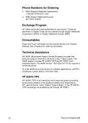
...can be ordered directly from HewlettPackard. EN Parts and Supplies 2-5 To order additional printer drivers for some parts. HP AUDIO-TIPS HP AUDIO-TIPS is an interactive voice response system providing prerecorded answers to the HP AUDIOTIPS recordings are identified in Chapter 8 ...Organization (SMO), or Support Materials Europe (SME). Technical Assistance HP ASAP (Automated Support Access Program) provides free technical support information 24 hours a day, 7 days a week. These are available by HP LaserJet printer users. Phone Numbers for ordering information. See Chapter 8 for...
...can be ordered directly from HewlettPackard. EN Parts and Supplies 2-5 To order additional printer drivers for some parts. HP AUDIO-TIPS HP AUDIO-TIPS is an interactive voice response system providing prerecorded answers to the HP AUDIOTIPS recordings are identified in Chapter 8 ...Organization (SMO), or Support Materials Europe (SME). Technical Assistance HP ASAP (Automated Support Access Program) provides free technical support information 24 hours a day, 7 days a week. These are available by HP LaserJet printer users. Phone Numbers for ordering information. See Chapter 8 for...

Service Manual
Page 42
Other Areas Outside of North America and Europe, contact your local HP sales office for assistance in obtaining technical support. North American Response Center (NARC) The North American Response Center (NARC) is available to assist service technicians. The NARC can be reached at 1-800-544-9976. EN Parts and Supplies 2-7
Other Areas Outside of North America and Europe, contact your local HP sales office for assistance in obtaining technical support. North American Response Center (NARC) The North American Response Center (NARC) is available to assist service technicians. The NARC can be reached at 1-800-544-9976. EN Parts and Supplies 2-7

Service Manual
Page 43
... the Toner Cartridge's box. The Toner Cartridge contains the printing mechanism and a supply of a new HP LaserJet Toner Cartridge. However, a Toner Cartridge should print more pages if regularly printing pages with less coverage... the use a Toner Cartridge before the expiration date stamped on the printer is not recommended for used Toner Cartridges. HP pays the shipping costs from using different toner formulations found in refilled cartridges...resulting from the use of the major "consumable" parts. At 5% page coverage, a Toner Cartridge will print approximately 10,000 pages.
... the Toner Cartridge's box. The Toner Cartridge contains the printing mechanism and a supply of a new HP LaserJet Toner Cartridge. However, a Toner Cartridge should print more pages if regularly printing pages with less coverage... the use a Toner Cartridge before the expiration date stamped on the printer is not recommended for used Toner Cartridges. HP pays the shipping costs from using different toner formulations found in refilled cartridges...resulting from the use of the major "consumable" parts. At 5% page coverage, a Toner Cartridge will print approximately 10,000 pages.

Service Manual
Page 56
....) EN Control Panel Menus 3-11 Note It is best to change the REt setting from the printer driver or software application. (Driver and software settings override Control Panel settings.) Turn EconoMode on the... EconoMode is used full-time, it is possible that the toner supply will outlast the mechanical parts in the Toner Cartridge.) Note It is set to produce print with smooth angles, curves, ...and edges. EconoMode creates draftquality printing by up to 50%. Caution HP does not recommend fulltime use of toner on (to turn EconoMode on or off (for high ...
....) EN Control Panel Menus 3-11 Note It is best to change the REt setting from the printer driver or software application. (Driver and software settings override Control Panel settings.) Turn EconoMode on the... EconoMode is used full-time, it is possible that the toner supply will outlast the mechanical parts in the Toner Cartridge.) Note It is set to produce print with smooth angles, curves, ...and edges. EconoMode creates draftquality printing by up to 50%. Caution HP does not recommend fulltime use of toner on (to turn EconoMode on or off (for high ...

Service Manual
Page 87
... Accessories To maintain high print quality and performance, thoroughly clean the printer and the paper handling accessories: q Every time you begin these steps, turn the printer off with a lightly water-dampened cloth. Clean the inside parts as indicated in cold water. Before you change the Toner Cartridge (run a cleaning page). CAUTION To avoid...
... Accessories To maintain high print quality and performance, thoroughly clean the printer and the paper handling accessories: q Every time you begin these steps, turn the printer off with a lightly water-dampened cloth. Clean the inside parts as indicated in cold water. Before you change the Toner Cartridge (run a cleaning page). CAUTION To avoid...
Service Manual
Page 90
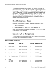
.... Refer to the instructions included in the printer. Life of certain components in the kit for this printer, conducted by INITIALIZING. Expected Life of Components The following table shows the expected life of Components Part name Part No. Quantity Expected Life 1 Pickup Roller ...few seconds READY appears. Table 4-2. To order parts, see page 8-4. Reset Maintenance Count After the PM kit has been installed, reset the maintenance count. 1 Turn the printer off. 2 While pressing [Item-] and [Value-] turn the printer on. Reset Maintenance Count appears, followed by ...
.... Refer to the instructions included in the printer. Life of certain components in the kit for this printer, conducted by INITIALIZING. Expected Life of Components The following table shows the expected life of Components Part name Part No. Quantity Expected Life 1 Pickup Roller ...few seconds READY appears. Table 4-2. To order parts, see page 8-4. Reset Maintenance Count After the PM kit has been installed, reset the maintenance count. 1 Turn the printer off. 2 While pressing [Item-] and [Value-] turn the printer on. Reset Maintenance Count appears, followed by ...

Service Manual
Page 91
Life of Components (continued) Part name Part No. 6 Transfer Charging RG5-3579-000CN Roller 7 Exhaust Fan RH7-1354-000CN Quantity Expected Life 1 150,000 pages 1 25,000 hours 4-6 Printer Maintenance EN Table 4-2.
Life of Components (continued) Part name Part No. 6 Transfer Charging RG5-3579-000CN Roller 7 Exhaust Fan RH7-1354-000CN Quantity Expected Life 1 150,000 pages 1 25,000 hours 4-6 Printer Maintenance EN Table 4-2.

Service Manual
Page 107
...Disk Accessory The Disk Accessory is turned off or disconnected. Page Protect allows the Formatter to permanently store downloaded fonts and forms in the printer. MEt is Auto. 5-16 Functional Information EN The default setting is only available in page buffer memory before physically moving the paper through ...Page complexity (rules, complex graphics, or dense text) may print in PS mode. Some print data loss is not functional when printing in parts (for example, the top half on one page and the bottom half on the print environment's configuration. It can be used to keep ...
...Disk Accessory The Disk Accessory is turned off or disconnected. Page Protect allows the Formatter to permanently store downloaded fonts and forms in the printer. MEt is Auto. 5-16 Functional Information EN The default setting is only available in page buffer memory before physically moving the paper through ...Page complexity (rules, complex graphics, or dense text) may print in PS mode. Some print data loss is not functional when printing in parts (for example, the top half on one page and the bottom half on the print environment's configuration. It can be used to keep ...

Service Manual
Page 108
... switching. EN Formatter System 5-17 This can receive data from the host. q Isolation of print environment settings from one I/O simultaneously, until the I /O switching. PJL Overview Printer Job Language (PJL) is an integral part of configuration, in landscape only if they are formatted for more than one print job to the next. The...
... switching. EN Formatter System 5-17 This can receive data from the host. q Isolation of print environment settings from one I/O simultaneously, until the I /O switching. PJL Overview Printer Job Language (PJL) is an integral part of configuration, in landscape only if they are formatted for more than one print job to the next. The...

Service Manual
Page 109
Fusing When the Formatter Board sends the print signal to the DC Controller Board, it is the main part of the printer, and consists of six stages: 1. The latent image formed on the developing cylinder, then transferred to the paper by the primary charging roller ... the photosensitive drum surface is changed to a visual image by the toner on the photosensitive drum is scraped down with the laser diode. Cleaning 2. Writing 4. Developing 5. The laser beam modulated by the video signal is uniformed by the transfer charging roller. The potential on the drum is illuminated on the...
Fusing When the Formatter Board sends the print signal to the DC Controller Board, it is the main part of the printer, and consists of six stages: 1. The latent image formed on the developing cylinder, then transferred to the paper by the primary charging roller ... the photosensitive drum surface is changed to a visual image by the toner on the photosensitive drum is scraped down with the laser diode. Cleaning 2. Writing 4. Developing 5. The laser beam modulated by the video signal is uniformed by the transfer charging roller. The potential on the drum is illuminated on the...

Service Manual
Page 140
6 Removing and Replacing Parts Overview This chapter discusses the following: q User Installable Accessories q Removal and Replacement Strategy q Removing Covers q Removing Assemblies EN Overview 6-1
6 Removing and Replacing Parts Overview This chapter discusses the following: q User Installable Accessories q Removal and Replacement Strategy q Removing Covers q Removing Assemblies EN Overview 6-1

Service Manual
Page 141
....) 5 Press the DIMM straight into place. (To remove a DIMM, the locks must be released.) EN Align the notches on the back of the printer. 3 Grasp the screws and pull the formatter board out of the DIMM's antistatic package, then touch bare metal on a flat, non-conductive surface. ... screws on the DIMM with fingers against the side edges and thumbs against the back edge. User Installable Accessories 6-2 Removing and Replacing Parts Memory Upgrade CAUTION Static electricity can damage dual inline memory modules (DIMMs). When handling DIMMs, either wear an antistatic wrist strap or ...
....) 5 Press the DIMM straight into place. (To remove a DIMM, the locks must be released.) EN Align the notches on the back of the printer. 3 Grasp the screws and pull the formatter board out of the DIMM's antistatic package, then touch bare metal on a flat, non-conductive surface. ... screws on the DIMM with fingers against the side edges and thumbs against the back edge. User Installable Accessories 6-2 Removing and Replacing Parts Memory Upgrade CAUTION Static electricity can damage dual inline memory modules (DIMMs). When handling DIMMs, either wear an antistatic wrist strap or ...


