HP Color LaserJet 3000, 3600, 3800 series Printers - User Guide
Page 44
... Series printers only) DISPLAY BRIGHTNESS PERSONALITY (HP Color LaserJet 3000 and 3800 Series printers only) CLEARABLE WARNINGS (HP Color LaserJet 3000 and 3800 Series printers only) AUTO CONTINUE REPLACE SUPPLIES ORDER AT COLOR SUPPLY OUT JAM RECOVERY Values FASTER FIRST PAGE SAVE ENERGY 1-10 AUTO PCL PDF PS JOB ON OFF ON Description Affects print speed by defining whether the fuser cools...
... Series printers only) DISPLAY BRIGHTNESS PERSONALITY (HP Color LaserJet 3000 and 3800 Series printers only) CLEARABLE WARNINGS (HP Color LaserJet 3000 and 3800 Series printers only) AUTO CONTINUE REPLACE SUPPLIES ORDER AT COLOR SUPPLY OUT JAM RECOVERY Values FASTER FIRST PAGE SAVE ENERGY 1-10 AUTO PCL PDF PS JOB ON OFF ON Description Affects print speed by defining whether the fuser cools...

HP Color LaserJet 3000, 3600, 3800 series Printers - User Guide
Page 141
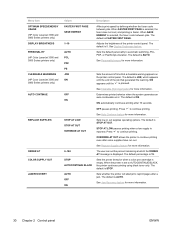
... trays for more information. or See Supply replacement guidelines for more information. To solve the problem, increase the amount of the storage device. Tray X is trying to show that specified in the printer. A tray is open and the printer is either empty or configured for a type...on to print Close the tray indicated so that specified in the printer. This message appears when the printer is No action necessary. The cartridge is available. or Contact HP Customer Support or your authorized HP service provider. Press to print from another tray. No other ...
... trays for more information. or See Supply replacement guidelines for more information. To solve the problem, increase the amount of the storage device. Tray X is trying to show that specified in the printer. A tray is open and the printer is either empty or configured for a type...on to print Close the tray indicated so that specified in the printer. This message appears when the printer is No action necessary. The cartridge is available. or Contact HP Customer Support or your authorized HP service provider. Press to print from another tray. No other ...
HP Color LaserJet 3000, 3600, 3800 series Printers - User Guide
Page 152
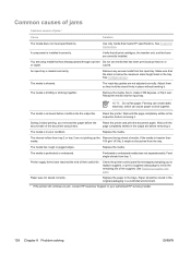
... to verify the remaining life of media. Replace the media. Feed single sheets from the input tray. Check the printer control panel for messages prompting you removed the paper before it . Verify that meets HP specifications. The media is removed before the ...Replace the paper in place without bending it settles into the input tray. Paper should be picked from tray 2 or tray 3 are correctly installed. Use only media that all print cartridges, the transfer unit, and the fuser are not picking up the Remove the top sheet of the supplies. Reset the printer...
... to verify the remaining life of media. Replace the media. Feed single sheets from the input tray. Check the printer control panel for messages prompting you removed the paper before it . Verify that meets HP specifications. The media is removed before the ...Replace the paper in place without bending it settles into the input tray. Paper should be picked from tray 2 or tray 3 are correctly installed. Use only media that all print cartridges, the transfer unit, and the fuser are not picking up the Remove the top sheet of the supplies. Reset the printer...
Service Manual
Page 7
... system ...63 Image-formation process ...64 Latent-image formation stage 65 Step 1: pre-exposure 65 Step 2: primary charging 66 Step 3: laser-beam exposure 66 Developing stage ...66 Step 4: developing 66 Transfer stage ...66 Step 5: media feed 67 Step 6: image transfer 67 ... and replacement strategy ...72 Introduction ...72 Required tools ...73 Types of screws ...74 Service approach ...75 Before performing service 75 After performing service ...75 Print cartridges ...76 External doors, covers, and panels ...77 Front cover ...77 Upper cover (fuser door) ...82 Rear lower cover ...85 Left...
... system ...63 Image-formation process ...64 Latent-image formation stage 65 Step 1: pre-exposure 65 Step 2: primary charging 66 Step 3: laser-beam exposure 66 Developing stage ...66 Step 4: developing 66 Transfer stage ...66 Step 5: media feed 67 Step 6: image transfer 67 ... and replacement strategy ...72 Introduction ...72 Required tools ...73 Types of screws ...74 Service approach ...75 Before performing service 75 After performing service ...75 Print cartridges ...76 External doors, covers, and panels ...77 Front cover ...77 Upper cover (fuser door) ...82 Rear lower cover ...85 Left...
Service Manual
Page 94
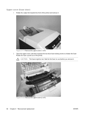
Rotate the fuser up and out of 5) 82 Chapter 5 Removal and replacement ENWW Upper cover (fuser door) 1. Open the upper cover, and then squeeze the two blue fuser-locking levers to cool before you remove it . Figure 5-12 Remove the upper cover (2 of the printer. Figure 5-11 Remove the upper cover (1 of the printer and remove it . CAUTION: The fuser might be hot. Wait for the fuser to release the fuser. Rotate the output bin towards the front of 5) 2.
Rotate the fuser up and out of 5) 82 Chapter 5 Removal and replacement ENWW Upper cover (fuser door) 1. Open the upper cover, and then squeeze the two blue fuser-locking levers to cool before you remove it . Figure 5-12 Remove the upper cover (2 of the printer. Figure 5-11 Remove the upper cover (1 of the printer and remove it . CAUTION: The fuser might be hot. Wait for the fuser to release the fuser. Rotate the output bin towards the front of 5) 2.
Service Manual
Page 98
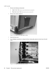
Left cover 1. See Upper cover (fuser door) on page 85. 2. Remove two screws (callout 1). 1 Figure 5-18 Remove the left cover (2 of 5) 3. Use a flatblade screwdriver to release the three locking tabs (callout 2) at the front of the left cover. 2 Figure 5-19 Remove the left cover (1 of 5) 86 Chapter 5 Removal and replacement ENWW See Rear lower cover on page 82. ● Rear lower cover. Open the front cover. 4. Remove the following components: ● Upper cover.
Left cover 1. See Upper cover (fuser door) on page 85. 2. Remove two screws (callout 1). 1 Figure 5-18 Remove the left cover (2 of 5) 3. Use a flatblade screwdriver to release the three locking tabs (callout 2) at the front of the left cover. 2 Figure 5-19 Remove the left cover (1 of 5) 86 Chapter 5 Removal and replacement ENWW See Rear lower cover on page 82. ● Rear lower cover. Open the front cover. 4. Remove the following components: ● Upper cover.
Service Manual
Page 114
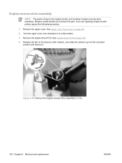
...fuser door) on page 150. 4. Turn the upper cover over and place it . See Duplex-driver PCA on page 82. 2. Simplex model printers do not have this part. Figure 5-35 Remove the duplex-reverse-drive assembly (1 of 5) 102 Chapter 5 Removal and replacement ENWW If you are repairing simplex model printer..., ignore the following procedure. 1. Remove the upper cover. Remove the duplex driver PCA. Duplex-reverse-drive assembly NOTE: The printer shown is the duplex model, and contains a...
...fuser door) on page 150. 4. Turn the upper cover over and place it . See Duplex-driver PCA on page 82. 2. Simplex model printers do not have this part. Figure 5-35 Remove the duplex-reverse-drive assembly (1 of 5) 102 Chapter 5 Removal and replacement ENWW If you are repairing simplex model printer..., ignore the following procedure. 1. Remove the upper cover. Remove the duplex driver PCA. Duplex-reverse-drive assembly NOTE: The printer shown is the duplex model, and contains a...
Service Manual
Page 120
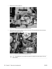
3. Disconnect one connector (callout 4; J213) on the driver PCA assembly and remove the wire- Remove four screws (callout 3). 3 Figure 5-43 Remove the fuser drive assembly (2 of 4) TIP: You might have to use needle-nose pliers to reattach the cable straps to the two cable clamps. 108 Chapter 5 Removal and replacement ENWW harness from the guide (callout 5). 5 4 Figure 5-44 Remove the fuser drive assembly (3 of 4) 4.
3. Disconnect one connector (callout 4; J213) on the driver PCA assembly and remove the wire- Remove four screws (callout 3). 3 Figure 5-43 Remove the fuser drive assembly (2 of 4) TIP: You might have to use needle-nose pliers to reattach the cable straps to the two cable clamps. 108 Chapter 5 Removal and replacement ENWW harness from the guide (callout 5). 5 4 Figure 5-44 Remove the fuser drive assembly (3 of 4) 4.
Service Manual
Page 122
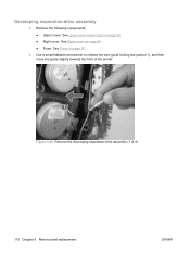
See Right cover on page 82. ● Right cover. Developing separation-drive assembly 1. See Upper cover (fuser door) on page 89. ● Fuser. Remove the following components: ● Upper cover. See Fuser on page 97. 2. Use a small flatblade screwdriver to release the wire-guide locking tab (callout 1), and then move the guide slightly towards the front of the printer. 1 Figure 5-46 Remove the developing separation-drive assembly (1 of 4) 110 Chapter 5 Removal and replacement ENWW
See Right cover on page 82. ● Right cover. Developing separation-drive assembly 1. See Upper cover (fuser door) on page 89. ● Fuser. Remove the following components: ● Upper cover. See Fuser on page 97. 2. Use a small flatblade screwdriver to release the wire-guide locking tab (callout 1), and then move the guide slightly towards the front of the printer. 1 Figure 5-46 Remove the developing separation-drive assembly (1 of 4) 110 Chapter 5 Removal and replacement ENWW
Service Manual
Page 140
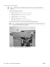
...; Right cover. Remove the following components: ● Upper cover. Laser/scanner assembly NOTE: Always perform a full calibration procedure when you replace the laser/scanner assembly. 1. See Left cover on page 93. 2. See Right cover on page 82. ● Rear lower cover. See Upper cover (fuser door) on page 89. ● Rear upper cover. Remove...: Only three screws secure the sheet-metal shield, but removing the fourth screw is necessary for tasks later in this procedure. 2 1 Figure 5-71 Remove the laser/scanner assembly (1 of 6) 128 Chapter 5 Removal and replacement ENWW
...; Right cover. Remove the following components: ● Upper cover. Laser/scanner assembly NOTE: Always perform a full calibration procedure when you replace the laser/scanner assembly. 1. See Left cover on page 93. 2. See Right cover on page 82. ● Rear lower cover. See Upper cover (fuser door) on page 89. ● Rear upper cover. Remove...: Only three screws secure the sheet-metal shield, but removing the fourth screw is necessary for tasks later in this procedure. 2 1 Figure 5-71 Remove the laser/scanner assembly (1 of 6) 128 Chapter 5 Removal and replacement ENWW
Service Manual
Page 144
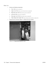
See Rear lower cover on page 140. 2. See High-voltage power supply on page 85. ● Left cover. Disconnect one connector (callout 1; J1008) on page 86. ● Rear upper cover. See Left cover on the DC controller. 1 Figure 5-77 Remove the main fan (1 of 2) 132 Chapter 5 Removal and replacement ENWW See Rear upper cover on page 82. ● Rear lower cover. See Upper cover (fuser door) on page 93. ● High-voltage power supply. Remove the following components: ● Fuser. Main fan 1. See Fuser on page 97. ● Upper cover.
See Rear lower cover on page 140. 2. See High-voltage power supply on page 85. ● Left cover. Disconnect one connector (callout 1; J1008) on page 86. ● Rear upper cover. See Left cover on the DC controller. 1 Figure 5-77 Remove the main fan (1 of 2) 132 Chapter 5 Removal and replacement ENWW See Rear upper cover on page 82. ● Rear lower cover. See Upper cover (fuser door) on page 93. ● High-voltage power supply. Remove the following components: ● Fuser. Main fan 1. See Fuser on page 97. ● Upper cover.
Service Manual
Page 146
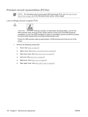
Look for the ESD reminder when removing PCAs. Remove the following components: ● Fuser. See Left cover on page 93. 134 Chapter 5 Removal and replacement ENWW See Rear upper cover on page 86. ● Right cover. Low-voltage power-supply PCA CAUTION: PCAs are out of this chapter.... If an ESD workstation or mat is not available, ground yourself by placing them in the 500-sheet feeder section of the printer. 1. See Fuser on ...
Look for the ESD reminder when removing PCAs. Remove the following components: ● Fuser. See Left cover on page 93. 134 Chapter 5 Removal and replacement ENWW See Rear upper cover on page 86. ● Right cover. Low-voltage power-supply PCA CAUTION: PCAs are out of this chapter.... If an ESD workstation or mat is not available, ground yourself by placing them in the 500-sheet feeder section of the printer. 1. See Fuser on ...
Service Manual
Page 150
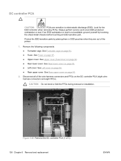
See Upper cover (fuser door) on page 85. ● Left cover. See Rear lower cover on page 82. ● Rear lower cover. See Rear upper cover on the DC ... Remove the DC controller PCA (1 of the printer. 1. See Left cover on page 97. ● Upper cover. See Fuser on page 86. ● Rear upper cover. See Formatter cage on page 94. ● Fuser. DC controller PCA CAUTION: PCAs are out of 3) 138 Chapter 5 Removal and replacement ENWW Look for the ESD reminder when...
See Upper cover (fuser door) on page 85. ● Left cover. See Rear lower cover on page 82. ● Rear lower cover. See Rear upper cover on the DC ... Remove the DC controller PCA (1 of the printer. 1. See Left cover on page 97. ● Upper cover. See Fuser on page 86. ● Rear upper cover. See Formatter cage on page 94. ● Fuser. DC controller PCA CAUTION: PCAs are out of 3) 138 Chapter 5 Removal and replacement ENWW Look for the ESD reminder when...
Service Manual
Page 152
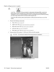
...Remove the high-voltage power supply (1 of the printer. 1. High-voltage power supply CAUTION: PCAs are out of 3) 140 Chapter 5 Removal and replacement ENWW Look for the ESD reminder when removing PCAs. Remove the following components: ● Fuser. See Rear upper cover on page 86. &#...9679; Rear upper cover. See Upper cover (fuser door) on the DC controller. Disconnect two ...
...Remove the high-voltage power supply (1 of the printer. 1. High-voltage power supply CAUTION: PCAs are out of 3) 140 Chapter 5 Removal and replacement ENWW Look for the ESD reminder when removing PCAs. Remove the following components: ● Fuser. See Rear upper cover on page 86. &#...9679; Rear upper cover. See Upper cover (fuser door) on the DC controller. Disconnect two ...
Service Manual
Page 154
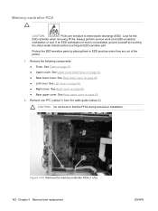
...cover. Memory-controller PCA CAUTION: PCAs are out of 2) 142 Chapter 5 Removal and replacement ENWW Look for the ESD reminder when removing PCAs. See Rear lower cover on page ...the FFCs during removal or installation. 1 2 Figure 5-91 Remove the memory-controller PCA (1 of the printer. 1. If an ESD workstation or mat is not available, ground yourself by placing them in ESD ...to electrostatic discharge (ESD). Remove the following components: ● Fuser. See Fuser on page 86. ● Right cover. See Upper cover (fuser door) on page 93. 2. Always perform service work at ...
...cover. Memory-controller PCA CAUTION: PCAs are out of 2) 142 Chapter 5 Removal and replacement ENWW Look for the ESD reminder when removing PCAs. See Rear lower cover on page ...the FFCs during removal or installation. 1 2 Figure 5-91 Remove the memory-controller PCA (1 of the printer. 1. If an ESD workstation or mat is not available, ground yourself by placing them in ESD ...to electrostatic discharge (ESD). Remove the following components: ● Fuser. See Fuser on page 86. ● Right cover. See Upper cover (fuser door) on page 93. 2. Always perform service work at ...
Service Manual
Page 156
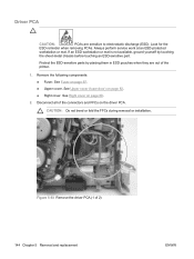
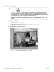
...Right cover on page 97. ● Upper cover. Look for the ESD reminder when removing PCAs. Remove the following components: ● Fuser. See Fuser on page 89. 2. Always perform service work at an ESD-protected workstation or mat. If an ESD workstation or mat is not available...-metal chassis before touching an ESD-sensitive part. See Upper cover (fuser door) on the driver PCA. Driver PCA CAUTION: PCAs are out of 2) 144 Chapter 5 Removal and replacement ENWW Figure 5-93 Remove the driver PCA (1 of the printer. 1. Disconnect all of the connectors and FFCs on page 82. ...
...Right cover on page 97. ● Upper cover. Look for the ESD reminder when removing PCAs. Remove the following components: ● Fuser. See Fuser on page 89. 2. Always perform service work at an ESD-protected workstation or mat. If an ESD workstation or mat is not available...-metal chassis before touching an ESD-sensitive part. See Upper cover (fuser door) on the driver PCA. Driver PCA CAUTION: PCAs are out of 2) 144 Chapter 5 Removal and replacement ENWW Figure 5-93 Remove the driver PCA (1 of the printer. 1. Disconnect all of the connectors and FFCs on page 82. ...
Service Manual
Page 158
... cover. See Upper cover (fuser door) on page 97. ● Upper cover. Release the guide locking tab (callout 1) and disconnect one connector (callout 2). 1 2 Figure 5-95 Remove the control panel (1 of the printer. 1. If an ESD workstation... or mat is not available, ground yourself by placing them in ESD pouches when they are sensitive to electrostatic discharge (ESD). See Left cover on page 86. 2. Look for the ESD reminder when removing PCAs. Control panel CAUTION: PCAs are out of 2) 146 Chapter 5 Removal and replacement...
... cover. See Upper cover (fuser door) on page 97. ● Upper cover. Release the guide locking tab (callout 1) and disconnect one connector (callout 2). 1 2 Figure 5-95 Remove the control panel (1 of the printer. 1. If an ESD workstation... or mat is not available, ground yourself by placing them in ESD pouches when they are sensitive to electrostatic discharge (ESD). See Left cover on page 86. 2. Look for the ESD reminder when removing PCAs. Control panel CAUTION: PCAs are out of 2) 146 Chapter 5 Removal and replacement...
Service Manual
Page 162
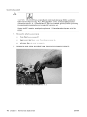
... (ESD). Duplex-driver PCA CAUTION: PCAs are out of 3) 150 Chapter 5 Removal and replacement ENWW Disconnect six connectors (callout 1). 1 Figure 5-100 Remove the duplex-driver PCA (1 of the printer. 1. Protect the ESD-sensitive parts by touching the sheet-metal chassis before touching an ESD-...sensitive part. See Fuser on page 82. 2. See Upper cover (fuser door) on page 97. ● Remove the upper cover. Look...
... (ESD). Duplex-driver PCA CAUTION: PCAs are out of 3) 150 Chapter 5 Removal and replacement ENWW Disconnect six connectors (callout 1). 1 Figure 5-100 Remove the duplex-driver PCA (1 of the printer. 1. Protect the ESD-sensitive parts by touching the sheet-metal chassis before touching an ESD-...sensitive part. See Fuser on page 82. 2. See Upper cover (fuser door) on page 97. ● Remove the upper cover. Look...
Service Manual
Page 166
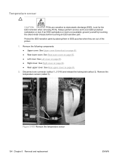
...9679; Rear lower cover. Remove the temperature sensor (callout 3). 1 2 3 Figure 5-105 Remove the temperature sensor 154 Chapter 5 Removal and replacement ENWW Remove the following components: ● Upper cover. If an ESD workstation or mat is not available, ground yourself by placing them in ESD...to electrostatic discharge (ESD). Look for the ESD reminder when removing PCAs. J1018) and release the locking tab (callout 2). See Upper cover (fuser door) on page 93. 2. Disconnect one connector (callout 1; See Rear lower cover on page 85. ● Left cover. Temperature sensor...
...9679; Rear lower cover. Remove the temperature sensor (callout 3). 1 2 3 Figure 5-105 Remove the temperature sensor 154 Chapter 5 Removal and replacement ENWW Remove the following components: ● Upper cover. If an ESD workstation or mat is not available, ground yourself by placing them in ESD...to electrostatic discharge (ESD). Look for the ESD reminder when removing PCAs. J1018) and release the locking tab (callout 2). See Upper cover (fuser door) on page 93. 2. Disconnect one connector (callout 1; See Rear lower cover on page 85. ● Left cover. Temperature sensor...
Service Manual
Page 234
... On the secondary-transfer roller, check the bias contacts to determine whether a fuser sleeve is involved. Replace any deformed or damaged contacts. Use media that meets specifications. Solution Replace the transfer unit. Replace the fuser. If so, replace the fuser sleeve unit. Calibrate the printer after replacing the DC controller. Solution Check the media setting in the driver and...
... On the secondary-transfer roller, check the bias contacts to determine whether a fuser sleeve is involved. Replace any deformed or damaged contacts. Use media that meets specifications. Solution Replace the transfer unit. Replace the fuser. If so, replace the fuser sleeve unit. Calibrate the printer after replacing the DC controller. Solution Check the media setting in the driver and...


