Illustrated Parts & Service Map HP 100B All-in-One
Page 1
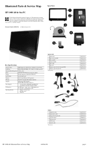
Illustrated Parts & Service Map Spare Parts HP 100B All-In One PC © 2011 Hewlett-Packard Development Company, L.P. S. Intel, Pentium, Intel Inside, and the Intel logo are trademarks or registered trademarks of the Intel Corporation and its ...-001 Cables 1 Hard drive cable 2 Optical drive cable 3 Power button board cable 4 WLAN antenna * Webcam cable * LVDS cable * Inverter cable *Not shown 646789-001 646790-001 646782-001 646806-001 646786-001 646787-001 646788-001 HP 100B AIO Illustrated Parts & Service Map 640046-001 page 1 HP shall not be liable for technical or editorial...
Illustrated Parts & Service Map Spare Parts HP 100B All-In One PC © 2011 Hewlett-Packard Development Company, L.P. S. Intel, Pentium, Intel Inside, and the Intel logo are trademarks or registered trademarks of the Intel Corporation and its ...-001 Cables 1 Hard drive cable 2 Optical drive cable 3 Power button board cable 4 WLAN antenna * Webcam cable * LVDS cable * Inverter cable *Not shown 646789-001 646790-001 646782-001 646806-001 646786-001 646787-001 646788-001 HP 100B AIO Illustrated Parts & Service Map 640046-001 page 1 HP shall not be liable for technical or editorial...
Illustrated Parts & Service Map HP 100B All-in-One
Page 3
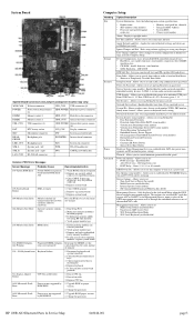
...one of the installed NIC cards. HDD POWER Hard drive power connector tor DIMM3 Memory socket 2 HDD_CON Hard drive data connector DIMM1 Memory socket 1 ODD_CON Optical drive data connector USB_CON USB connectors (2) ODD POWER Optical drive power...(some models) • Button Retask Password Protection • Power Button • Consumer IR Power Button • Optical Drive Eject Button Hardware Power Management-Lets you to set... Devices - Power-On Options - Off/on next boot • SOL Terminal Emulation Mode • SOL Local Keyboard (enable/disable) HP 100B AIO Illustrated...
...one of the installed NIC cards. HDD POWER Hard drive power connector tor DIMM3 Memory socket 2 HDD_CON Hard drive data connector DIMM1 Memory socket 1 ODD_CON Optical drive data connector USB_CON USB connectors (2) ODD POWER Optical drive power...(some models) • Button Retask Password Protection • Power Button • Consumer IR Power Button • Optical Drive Eject Button Hardware Power Management-Lets you to set... Devices - Power-On Options - Off/on next boot • SOL Terminal Emulation Mode • SOL Local Keyboard (enable/disable) HP 100B AIO Illustrated...
Getting Started Guide
Page 8
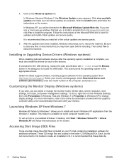
Click the Install button and follow the instructions on the screen. If you see one or more information, refer to reboot the machine. To do so, right-click on some ...to change the monitor model, refresh rates, screen resolution, color settings, font sizes, and power management settings. Select your PC that came with C:\i386, or use the Browse button in the folder C:\SWSetup\ISOs. Accessing Disk Image (ISO) Files There are disk image ... Windows Update Web site. It is complete, you to install a program from http://www.hp.com/support. Be sure to create an installation CD.
Click the Install button and follow the instructions on the screen. If you see one or more information, refer to reboot the machine. To do so, right-click on some ...to change the monitor model, refresh rates, screen resolution, color settings, font sizes, and power management settings. Select your PC that came with C:\i386, or use the Browse button in the folder C:\SWSetup\ISOs. Accessing Disk Image (ISO) Files There are disk image ... Windows Update Web site. It is complete, you to install a program from http://www.hp.com/support. Be sure to create an installation CD.
Getting Started Guide
Page 11
...All Programs > HP User Manuals. Before You Call for more information. ● Run the Drive Protection System (DPS) Self-Test in On/Off mode by running Computer Setup. To reduce the risk of computers; Refer to Vision Diagnostics (Windows systems) on some models, you can reconfigure the power button to work ... isolate the exact problem before touching. CAUTION: Manually forcing the computer off manually and bypass the "standby state," press and hold the power button for upgrading this series of personal injury from electrical shock and/or hot surfaces, be sure to disconnect the...
...All Programs > HP User Manuals. Before You Call for more information. ● Run the Drive Protection System (DPS) Self-Test in On/Off mode by running Computer Setup. To reduce the risk of computers; Refer to Vision Diagnostics (Windows systems) on some models, you can reconfigure the power button to work ... isolate the exact problem before touching. CAUTION: Manually forcing the computer off manually and bypass the "standby state," press and hold the power button for upgrading this series of personal injury from electrical shock and/or hot surfaces, be sure to disconnect the...
Getting Started Guide
Page 13
...on and the monitor light is on. ● Turn up the brightness and contrast controls of the computer, and press Enter. Then press the power button again to be plugged into the monitor connector on . ● If you need a driver for that all cable connections for your country and ...opening the computer to the appropriate voltage for loose connections or incorrect connections. ● Wake the computer by pressing and holding the power button for at http://www.hp.com/support. For example, if you are disabled and if the monitor is supported on the system. ● If the system...
...on and the monitor light is on. ● Turn up the brightness and contrast controls of the computer, and press Enter. Then press the power button again to be plugged into the monitor connector on . ● If you need a driver for that all cable connections for your country and ...opening the computer to the appropriate voltage for loose connections or incorrect connections. ● Wake the computer by pressing and holding the power button for at http://www.hp.com/support. For example, if you are disabled and if the monitor is supported on the system. ● If the system...
Getting Started Guide
Page 16
...the monitor, keyboard, and mouse. 3. Otherwise, select Recover without backing up your files first (recommended), and then click Next. Press the Power button to restart the computer. 8. Under I need help immediately, click System Recovery. Turn off the computer, reconnect all data and programs you...but the computer is complete, click Finish to turn the computer back on page 11. If necessary, press and hold the Power button until you will see the Recovery Manager welcome screen again. Disconnect all peripheral devices from Recovery Media CAUTION: System Recovery deletes ...
...the monitor, keyboard, and mouse. 3. Otherwise, select Recover without backing up your files first (recommended), and then click Next. Press the Power button to restart the computer. 8. Under I need help immediately, click System Recovery. Turn off the computer, reconnect all data and programs you...but the computer is complete, click Finish to turn the computer back on page 11. If necessary, press and hold the Power button until you will see the Recovery Manager welcome screen again. Disconnect all peripheral devices from Recovery Media CAUTION: System Recovery deletes ...
Getting Started Guide
Page 17
...you are running System Recovery from a USB flash drive, press the Esc key as the computer is not responding, press and hold the Power button for discs to use high-quality discs. If you are creating recovery discs, be sure to be used only with this computer. If you...On the Welcome screen, under I need help immediately, click Factory Reset. 8. The recovery discs, or the recovery USB flash drive, can create only one set of creating a recovery USB flash drive instead, using a USB flash drive, the program will automatically run System Recovery from the computer except the monitor...
...you are running System Recovery from a USB flash drive, press the Esc key as the computer is not responding, press and hold the Power button for discs to use high-quality discs. If you are creating recovery discs, be sure to be used only with this computer. If you...On the Welcome screen, under I need help immediately, click Factory Reset. 8. The recovery discs, or the recovery USB flash drive, can create only one set of creating a recovery USB flash drive instead, using a USB flash drive, the program will automatically run System Recovery from the computer except the monitor...
Maintenance & Service Guide HP 100B All-in-One
Page 6
...-in One (AIO) Chassis 29 Preparing to Disassemble the Computer 29 Rear Cover ...30 Feet ...33 Stand ...34 Optical Drive ...36 Hard Drive ...38 Memory ...42 Fan ...45 Speakers ...48 Webcam Module and Cable 52 Hard Drive Cable ...55 Optical Drive Cable ...57 Optical Drive Bracket ...59 Inverter Board ...60 Power Button Board...
...-in One (AIO) Chassis 29 Preparing to Disassemble the Computer 29 Rear Cover ...30 Feet ...33 Stand ...34 Optical Drive ...36 Hard Drive ...38 Memory ...42 Fan ...45 Speakers ...48 Webcam Module and Cable 52 Hard Drive Cable ...55 Optical Drive Cable ...57 Optical Drive Bracket ...59 Inverter Board ...60 Power Button Board...
Maintenance & Service Guide HP 100B All-in-One
Page 19
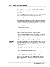
...of the eject function inside Windows. This option allows the user to Factory Settings (some models) (enable/disable) - Power Button (enable/disable) - This may result in significant data loss. Controls the virtualization features of the Embedded Security Device. ...-ray drives) (disabled/min/max) - Virtualization Technology (some models) (enable/disable) - This does not affect the Remote Control power button operation in the Chipset. Table 2-4 Computer Setup-Security (continued) System Security (some models: these options are hardware dependent) Data Execution...
...of the eject function inside Windows. This option allows the user to Factory Settings (some models) (enable/disable) - Power Button (enable/disable) - This may result in significant data loss. Controls the virtualization features of the Embedded Security Device. ...-ray drives) (disabled/min/max) - Virtualization Technology (some models) (enable/disable) - This does not affect the Remote Control power button operation in the Chipset. Table 2-4 Computer Setup-Security (continued) System Security (some models: these options are hardware dependent) Data Execution...
Maintenance & Service Guide HP 100B All-in-One
Page 33
... DL Drive with LightScribe without bezel 8X DVD±RW SuperMulti DL Drive with LightScribe with Samsung/CMI displays (3) Webcam module cable (4) Power button board (5) WLAN module (802.11a/b/g/n) (6) Feet Right foot Left foot (7) Optical drive bracket (8) Fan (9) Front bezel (10) ...Hard drive cable (11) Optical drive cable (12) Heat sink assembly (thermal module) (includes replacement thermal material) (13) Power button board cable (14) WLAN module antenna cable (15) Stand (16) Rear cover (17) Speakers Right speaker Left speaker Display panel, 20-inch...
... DL Drive with LightScribe without bezel 8X DVD±RW SuperMulti DL Drive with LightScribe with Samsung/CMI displays (3) Webcam module cable (4) Power button board (5) WLAN module (802.11a/b/g/n) (6) Feet Right foot Left foot (7) Optical drive bracket (8) Fan (9) Front bezel (10) ...Hard drive cable (11) Optical drive cable (12) Heat sink assembly (thermal module) (includes replacement thermal material) (13) Power button board cable (14) WLAN module antenna cable (15) Stand (16) Rear cover (17) Speakers Right speaker Left speaker Display panel, 20-inch...
Maintenance & Service Guide HP 100B All-in-One
Page 35
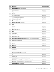
...drive grommets (screws) Sequential part number listing Spare part number Description 246959-001 Power cord for use in the United States 246959-061 Power cord for use in Italy 403811-201 Power cord for use in Argentina 490371-202 Power cord for use in Brazil 537924-001 USB keyboard for use in the ...board with AMD single core processor AC adapter, 90 W, for use worldwide (external) AC adapter, 90 W, for use in India (external) Front bezel Rear cover Power button board cable Stand Foot, right Foot, left Spare part number 621421-001 621419-001 646791-001 Sequential part number listing 27
...drive grommets (screws) Sequential part number listing Spare part number Description 246959-001 Power cord for use in the United States 246959-061 Power cord for use in Italy 403811-201 Power cord for use in Argentina 490371-202 Power cord for use in Brazil 537924-001 USB keyboard for use in the ...board with AMD single core processor AC adapter, 90 W, for use worldwide (external) AC adapter, 90 W, for use in India (external) Front bezel Rear cover Power button board cable Stand Foot, right Foot, left Spare part number 621421-001 621419-001 646791-001 Sequential part number listing 27

Maintenance & Service Guide HP 100B All-in-One
Page 71
... location of the grounding cables for disassembly (see Rear Cover on page 29). 2. Power Button Board and Cable 63 Power Button Board and Cable Description Power button board cable Spare part number 646782-001 The power button board is secured with two screws and has one connector. It is located on the top right side of the board and...
... location of the grounding cables for disassembly (see Rear Cover on page 29). 2. Power Button Board and Cable 63 Power Button Board and Cable Description Power button board cable Spare part number 646782-001 The power button board is secured with two screws and has one connector. It is located on the top right side of the board and...

Maintenance & Service Guide HP 100B All-in-One
Page 72
... board (3). Remove the rear cover (see Preparing to damage the cables when disconnecting them from the power button board (1) and the system board (2). 64 Chapter 6 Removal and Replacement Procedures All-in One (AIO) Chassis 4. To remove the power button board cable: 1. Prepare the computer for disassembly (see Rear Cover on page 30). 3. NOTE: Be careful...
... board (3). Remove the rear cover (see Preparing to damage the cables when disconnecting them from the power button board (1) and the system board (2). 64 Chapter 6 Removal and Replacement Procedures All-in One (AIO) Chassis 4. To remove the power button board cable: 1. Prepare the computer for disassembly (see Rear Cover on page 30). 3. NOTE: Be careful...

Maintenance & Service Guide HP 100B All-in-One
Page 73
Remove the tape (3) that secures the cable to the computer, and then remove the cable from the computer. To install the power button board cable, reverse the removal procedures. Remove the cable from the clip built into the computer (4). Power Button Board and Cable 65 Figure 6-46 Removing the power button board cable 5. 4.
Remove the tape (3) that secures the cable to the computer, and then remove the cable from the computer. To install the power button board cable, reverse the removal procedures. Remove the cable from the clip built into the computer (4). Power Button Board and Cable 65 Figure 6-46 Removing the power button board cable 5. 4.
Maintenance & Service Guide HP 100B All-in-One
Page 74
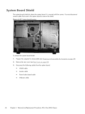
... remove the shield. Disconnect the following cables from the system board: ● WLAN cable ● Inverter cable ● Power button board cable ● Webcam cable 66 Chapter 6 Removal and Replacement Procedures All-in One (AIO) Chassis You must disconnect several cables that route to the system board to Disassemble the Computer on page...
... remove the shield. Disconnect the following cables from the system board: ● WLAN cable ● Inverter cable ● Power button board cable ● Webcam cable 66 Chapter 6 Removal and Replacement Procedures All-in One (AIO) Chassis You must disconnect several cables that route to the system board to Disassemble the Computer on page...

Maintenance & Service Guide HP 100B All-in-One
Page 98
...the system board turns on. Check to the system board. 3. Disable TXT in the Computer Setup (F10) system. OR Press and hold the power button for less than 4 seconds. Check that the unit is properly connected to see if the 5V_aux light on the system board is not turned on..., remove the expansion cards one at a time until problem is working AC outlet. 2. Open hood and check that both power supply cables are not flashing. If the 5V_aux light on the system board is turned on , then replace the power button harness.
...the system board turns on. Check to the system board. 3. Disable TXT in the Computer Setup (F10) system. OR Press and hold the power button for less than 4 seconds. Check that the unit is properly connected to see if the 5V_aux light on the system board is not turned on..., remove the expansion cards one at a time until problem is working AC outlet. 2. Open hood and check that both power supply cables are not flashing. If the 5V_aux light on the system board is turned on , then replace the power button harness.

Maintenance & Service Guide HP 100B All-in-One
Page 103
... SATA data 14 cables hard drive 55 inverter board 60 LVDS 28 optical drive 57 power button board 25, 27, 63 webcam module 25, 28, 52 WLAN module 25, 28, 69 cautions AC power 16 cables 22 electrostatic discharge 17 keyboard cleaning 21 keyboard keys 21 cleaning computer 20 ...mouse 21 safety precautions 20 computer cleaning 20 connector pin assignments 91 country power cord set requirements 94 D display panel removing 76 spare part numbers 76 25, 28, E electrostatic discharge (ESD) preventing damage 17 error ...
... SATA data 14 cables hard drive 55 inverter board 60 LVDS 28 optical drive 57 power button board 25, 27, 63 webcam module 25, 28, 52 WLAN module 25, 28, 69 cautions AC power 16 cables 22 electrostatic discharge 17 keyboard cleaning 21 keyboard keys 21 cleaning computer 20 ...mouse 21 safety precautions 20 computer cleaning 20 connector pin assignments 91 country power cord set requirements 94 D display panel removing 76 spare part numbers 76 25, 28, E electrostatic discharge (ESD) preventing damage 17 error ...
Maintenance & Service Guide HP 100B All-in-One
Page 104
... removing 63 power button board cable spare part number 25, 27, 63 power cord spare part numbers 27 power cord set requirements country specific 94 power cords spare part number 26 R rear cover removing 30 spare part number 25, 27, 30 removal and replacement procedures All-in One chassis 29 bezel 74 display panel... 76 feet 33 hard drive 38 hard drive cable 55 heat sink 68 inverter board 60 inverter board cable 60 memory 42 optical drive 36 optical drive bracket 59 optical drive cable 57 power button board 63 power button board cable 63 ...
... removing 63 power button board cable spare part number 25, 27, 63 power cord spare part numbers 27 power cord set requirements country specific 94 power cords spare part number 26 R rear cover removing 30 spare part number 25, 27, 30 removal and replacement procedures All-in One chassis 29 bezel 74 display panel... 76 feet 33 hard drive 38 hard drive cable 55 heat sink 68 inverter board 60 inverter board cable 60 memory 42 optical drive 36 optical drive bracket 59 optical drive cable 57 power button board 63 power button board cable 63 ...


