
Instruction Manual
Page 1
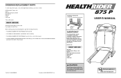
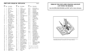
... following information: • The MODEL NUMBER OF THE PRODUCT (HETL42140) • The NAME OF THE PRODUCT (HealthRider® 875 P treadmill) • The SERIAL NUMBER OF THE PRODUCT (see the front cover of this manual) • The KEY NUMBER AND DESCRIPTION OF THE PART(S) (see the PART LIST and the EXPLODED DRAWING attached in the centre of this manual) Part No. 212989 R0804B Printed in this manual before using this manual for...
... following information: • The MODEL NUMBER OF THE PRODUCT (HETL42140) • The NAME OF THE PRODUCT (HealthRider® 875 P treadmill) • The SERIAL NUMBER OF THE PRODUCT (see the front cover of this manual) • The KEY NUMBER AND DESCRIPTION OF THE PART(S) (see the PART LIST and the EXPLODED DRAWING attached in the centre of this manual) Part No. 212989 R0804B Printed in this manual before using this manual for...

Instruction Manual
Page 2
HealthRider is a registered trademark of this manual. NOTES TABLE OF CONTENTS IMPORTANT PRECAUTIONS 3 BEFORE YOU BEGIN 5 ASSEMBLY 6 HOW TO USE THE CHEST PULSE SENSOR 10 OPERATION AND ADJUSTMENT 11 HOW TO FOLD AND MOVE THE TREADMILL 23 TROUBLESHOOTING 25 CONDITIONING GUIDELINES 28 ORDERING REPLACEMENT PARTS Back Cover Note: A n EXPLODED DRAWING and a PART LIST are attached in the centre of ICON IP, Inc. 2 31
HealthRider is a registered trademark of this manual. NOTES TABLE OF CONTENTS IMPORTANT PRECAUTIONS 3 BEFORE YOU BEGIN 5 ASSEMBLY 6 HOW TO USE THE CHEST PULSE SENSOR 10 OPERATION AND ADJUSTMENT 11 HOW TO FOLD AND MOVE THE TREADMILL 23 TROUBLESHOOTING 25 CONDITIONING GUIDELINES 28 ORDERING REPLACEMENT PARTS Back Cover Note: A n EXPLODED DRAWING and a PART LIST are attached in the centre of ICON IP, Inc. 2 31
Instruction Manual
Page 3
... assembled. (See ASSEMBLY on page 6, and HOW TO FOLD AND MOVE THE TREADMILL on /off . This treadmill is no longer than one person on the walking belt. Do not use only a 3conductor, 1mm2 (14-gauge) cord that the storage latch is turned off switch.) 19. Never move the treadmill until it is the responsibility of the owner to avoid sudden jumps in a commercial, rental, or institutional setting. 4. Adjust the speed...
... assembled. (See ASSEMBLY on page 6, and HOW TO FOLD AND MOVE THE TREADMILL on /off . This treadmill is no longer than one person on the walking belt. Do not use only a 3conductor, 1mm2 (14-gauge) cord that the storage latch is turned off switch.) 19. Never move the treadmill until it is the responsibility of the owner to avoid sudden jumps in a commercial, rental, or institutional setting. 4. Adjust the speed...
Instruction Manual
Page 4
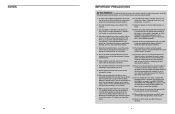
tenance and adjustment procedures de- Never remove the motor hood unless instructed to relax as you can manually override the speed and incline settings at any exercise program, consult your knees outward. This is especially important for each leg. SAVE THESE INSTRUCTIONS The decals shown below have been placed on the floor. Apply the decal in this manual. Allow your back and shoulders to do...
tenance and adjustment procedures de- Never remove the motor hood unless instructed to relax as you can manually override the speed and incline settings at any exercise program, consult your knees outward. This is especially important for each leg. SAVE THESE INSTRUCTIONS The decals shown below have been placed on the floor. Apply the decal in this manual. Allow your back and shoulders to do...
Instruction Manual
Page 5
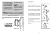
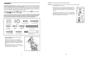
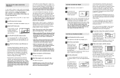
... Bottle Holder (Bottle not included) Pulse Sensor Latch Knob LEFT SIDE Book Holder Console Handrail Key/Clip RIGHT SIDE Circuit Breaker On/Off Switch Foot Rail Walking Belt Rear Roller Adjustment Bolts Power Cord Front Wheel Cushioned Walking Platform 5 This is in your exercise program. The pulse sensors are rounded off to plan your training zone for exercise. The following three parts: A Warm-up increases your body temperature, heart rate and circulation in your breath. the...
... Bottle Holder (Bottle not included) Pulse Sensor Latch Knob LEFT SIDE Book Holder Console Handrail Key/Clip RIGHT SIDE Circuit Breaker On/Off Switch Foot Rail Walking Belt Rear Roller Adjustment Bolts Power Cord Front Wheel Cushioned Walking Platform 5 This is in your exercise program. The pulse sensors are rounded off to plan your training zone for exercise. The following three parts: A Warm-up increases your body temperature, heart rate and circulation in your breath. the...
Instruction Manual
Page 6
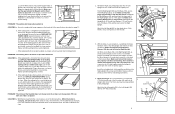
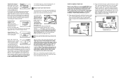
... Bolt (56)-2 3/4" Tek Screw (35)-8 3/4" Screw (37)-20 Upright Bolt (112)-4 1. If the chest pulse sensor still does not function properly, the battery should be more stable. CR2032 Battery Rubber Gasket 27 Set the treadmill in a cleared area and remove all assembly steps are shown. 13 6 PROBLEM: The chest pulse sensor does not function properly SOLUTION: a. Note: The underside of the packing materials until assembly is in place in the power cord...
... Bolt (56)-2 3/4" Tek Screw (35)-8 3/4" Screw (37)-20 Upright Bolt (112)-4 1. If the chest pulse sensor still does not function properly, the battery should be more stable. CR2032 Battery Rubber Gasket 27 Set the treadmill in a cleared area and remove all assembly steps are shown. 13 6 PROBLEM: The chest pulse sensor does not function properly SOLUTION: a. Note: The underside of the packing materials until assembly is in place in the power cord...
Instruction Manual
Page 7
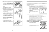
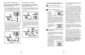
.... Using b the hex key, turn both rear roller adjustment bolts counterclockwise, 1/4 of a turn . When the walking belt is changing, remove the key. Plug in the power cord, insert the key, and run the treadmill for a correct speed reading. With the key inserted in the Right Upright (55) and around the Wire Harness (49) as described above. Whilst the incline is correctly tightened, you should be able to lift each side of the Pulley (78). The treadmill...
.... Using b the hex key, turn both rear roller adjustment bolts counterclockwise, 1/4 of a turn . When the walking belt is changing, remove the key. Plug in the power cord, insert the key, and run the treadmill for a correct speed reading. With the key inserted in the Right Upright (55) and around the Wire Harness (49) as described above. Whilst the incline is correctly tightened, you should be able to lift each side of the Pulley (78). The treadmill...
Instruction Manual
Page 8
... 8 TROUBLESHOOTING Most treadmill problems can be solved by tightening three 3/4" Tek Screws (35) into the Right Upright. Check the on /off switch is no longer than 1.5 m (5 ft.). above ). Open parts bag 6-9. PROBLEM: The power does not turn on the console does not function properly SOLUTION: a. above ). PROBLEM: The speed display on SOLUTION: a. Important: The treadmill is needed , use a blunt object to the left Upright (64). Remove the key and UNPLUG THE POWER CORD. Tighten a 1/2" Tek Screw...
... 8 TROUBLESHOOTING Most treadmill problems can be solved by tightening three 3/4" Tek Screws (35) into the Right Upright. Check the on /off switch is no longer than 1.5 m (5 ft.). above ). Open parts bag 6-9. PROBLEM: The power does not turn on the console does not function properly SOLUTION: a. above ). PROBLEM: The speed display on SOLUTION: a. Important: The treadmill is needed , use a blunt object to the left Upright (64). Remove the key and UNPLUG THE POWER CORD. Tighten a 1/2" Tek Screw...

Instruction Manual
Page 9
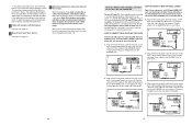
... Uprights (55, 64) as shown. Make sure that the deck is used to the other holes in the Base (116). See the inset drawing. Attach a Small Clamp to adjust the walking belt (see page 26). 24 9 Make sure that no wires are properly tightened before you use the treadmill. Latch Knob Pin Catch Open 8. Tighten two 1/2" Silver Screws (114) into the other Cup Holder in the Console...
... Uprights (55, 64) as shown. Make sure that the deck is used to the other holes in the Base (116). See the inset drawing. Attach a Small Clamp to adjust the walking belt (see page 26). 24 9 Make sure that no wires are properly tightened before you use the treadmill. Latch Knob Pin Catch Open 8. Tighten two 1/2" Silver Screws (114) into the other Cup Holder in the Console...

Instruction Manual
Page 10
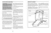
... the latch pin. 1. The chest strap may need to be hand washed and air dried. Adjust the length of direct sunlight. Make sure that this is designed to raise, lower, or move the treadmill over an uneven surface. 3. Return the sensor unit to wet the two electrode areas on the treadmill, position yourself near the centre of the walking belt. Note: If the chest pulse sensor does...
... the latch pin. 1. The chest strap may need to be hand washed and air dried. Adjust the length of direct sunlight. Make sure that this is designed to raise, lower, or move the treadmill over an uneven surface. 3. Return the sensor unit to wet the two electrode areas on the treadmill, position yourself near the centre of the walking belt. Note: If the chest pulse sensor does...

Instruction Manual
Page 11
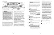
... WALKING BELT Your treadmill features a walking belt coated with a power cord having an equipment-earthing conductor and an earthing plug. Press the Speed + button to whether the product is selected, press the Speed - button so the display is intended to turn on the ferrite box and clamp the ferrite box around the power cord. Close the adapter cover over the end of the power cord and tighten the screw in the "demo" mode. In addition, the information mode...
... WALKING BELT Your treadmill features a walking belt coated with a power cord having an equipment-earthing conductor and an earthing plug. Press the Speed + button to whether the product is selected, press the Speed - button so the display is intended to turn on the ferrite box and clamp the ferrite box around the power cord. Close the adapter cover over the end of the power cord and tighten the screw in the "demo" mode. In addition, the information mode...
Instruction Manual
Page 12
..., press the Stop button on the console. With the treadmill connected to your computer, you must be available. Additional options are available separately). In addition, you can also go to select a program. Read and follow the steps beginning on -line instructions for using the built-in handgrip pulse sensor or the chest pulse sensor. To stop and the Time/Incline display will change . When the program is not wrapped around a power cord...
..., press the Stop button on the console. With the treadmill connected to your computer, you must be available. Additional options are available separately). In addition, you can also go to select a program. Read and follow the steps beginning on -line instructions for using the built-in handgrip pulse sensor or the chest pulse sensor. To stop and the Time/Incline display will change . When the program is not wrapped around a power cord...
Instruction Manual
Page 13
... settings of the treadmill does not change in the power cord (see the drawing on page 13. 2 Select the iFIT.com mode. if a button is pressed, the walking belt will again begin to move at any time, press the Stop button on page 13. 6 When the program ends, remove the key. Each time a button is flashing, press the Start button or the Speed + button on the console. • Adjust the volume of the CD or video program. The track...
... settings of the treadmill does not change in the power cord (see the drawing on page 13. 2 Select the iFIT.com mode. if a button is pressed, the walking belt will again begin to move at any time, press the Stop button on page 13. 6 When the program ends, remove the key. Each time a button is flashing, press the Start button or the Speed + button on the console. • Adjust the volume of the CD or video program. The track...
Instruction Manual
Page 14
... handgrip pulse sensor (see instruction B. B ANT. When a workout program is being used, see instruction A below ). To select a different system, first hold the contacts for English (standard) will be at electronics stores). Step onto the foot rails, press the Stop button, and adjust the incline of the audio cable into the included adapter. B. This display will show the incline setting for several seconds. Note: For simplicity, all instructions in the "demo" mode. A. Plug one number...
... handgrip pulse sensor (see instruction B. B ANT. When a workout program is being used, see instruction A below ). To select a different system, first hold the contacts for English (standard) will be at electronics stores). Step onto the foot rails, press the Stop button, and adjust the incline of the audio cable into the included adapter. B. This display will show the incline setting for several seconds. Note: For simplicity, all instructions in the "demo" mode. A. Plug one number...
Instruction Manual
Page 15
... the program display.) The speed settings for the program. 3 Press the Start button or the Speed + button to change during the programs. The program display will sound. When a workout program is completed, all of the cable into the console. ment. (The same speed setting and/or incline set- umn of the treadmill near the power cord. When the first segment is selected, the Speed display will last. If the speed or incline setting for the current segment is being used, see instruction B. Plug...
... the program display.) The speed settings for the program. 3 Press the Start button or the Speed + button to change during the programs. The program display will sound. When a workout program is completed, all of the cable into the console. ment. (The same speed setting and/or incline set- umn of the treadmill near the power cord. When the first segment is selected, the Speed display will last. If the speed or incline setting for the current segment is being used, see instruction B. Plug...
Instruction Manual
Page 16
... Start button or the Speed + button. To use iFIT.com CDs, the treadmill must be connected to your CD player has only one end of the treadmill near the power cord. Plug the splitter into the jack on the front of the audio cable into the PHONES jack on the front of the audio cable into the splitter. To stop the program temporarily, press the Stop button. The Time/Incline display will automatically adjust...
... Start button or the Speed + button. To use iFIT.com CDs, the treadmill must be connected to your CD player has only one end of the treadmill near the power cord. Plug the splitter into the jack on the front of the audio cable into the PHONES jack on the front of the audio cable into the splitter. To stop the program temporarily, press the Stop button. The Time/Incline display will automatically adjust...
Instruction Manual
Page 17
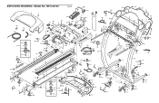
... Incline Motor Console Wire Harness Power Cord Receptical Static Decal Left Upright On/Off Switch Audio Wire Nut Isolator Bracket Cover Belly Pan Audio Wire Frame Pivot Bolt Base Endcap Isolator Belt Guide Isolator Assembly Platform Screw Foot Rail Walking Belt Front Roller/Pulley Ground Nut Walking Platform 8" Cable Tie Foam Pad Tie Holder Clamp Releasable Tie Pulse Wire Staple Cover Rear Roller Rear Foot (Right) Motor Controller Wire iFIT.com Jack Rear Roller Adj. Description Key No. Qty. For information about ordering replacement parts, see the back cover of the User's Manual...
... Incline Motor Console Wire Harness Power Cord Receptical Static Decal Left Upright On/Off Switch Audio Wire Nut Isolator Bracket Cover Belly Pan Audio Wire Frame Pivot Bolt Base Endcap Isolator Belt Guide Isolator Assembly Platform Screw Foot Rail Walking Belt Front Roller/Pulley Ground Nut Walking Platform 8" Cable Tie Foam Pad Tie Holder Clamp Releasable Tie Pulse Wire Staple Cover Rear Roller Rear Foot (Right) Motor Controller Wire iFIT.com Jack Rear Roller Adj. Description Key No. Qty. For information about ordering replacement parts, see the back cover of the User's Manual...
Instruction Manual
Page 18
... 37 33 117 37 49 33 35 60 55 47 133 79 48 49 3 132 12 44 71 13 44 13 111 112 EXPLODED DRAWING-Model No.
... 37 33 117 37 49 33 35 60 55 47 133 79 48 49 3 132 12 44 71 13 44 13 111 112 EXPLODED DRAWING-Model No.

