
English Manual
Page 1
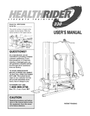
...serial number in this manual before using this manual for future reference. ¨ USERÕS MANUAL PATENT PENDING Serial Number Decal QUESTIONS? MST CAUTION Read all precautions and instructions in the space above. As a manufacturer, we will provide immediate assistance, free of charge to you have questions, or if there are missing or damaged parts... HRSY23080 Serial No. TO AVOID UNNECESSARY DELAYS, PLEASE CALL DIRECT TO OUR TOLL-FREE CUSTOMER HOT LINE. The serial number is found in the location shown below. If you . Save this equipment. The trained technicians on...
...serial number in this manual before using this manual for future reference. ¨ USERÕS MANUAL PATENT PENDING Serial Number Decal QUESTIONS? MST CAUTION Read all precautions and instructions in the space above. As a manufacturer, we will provide immediate assistance, free of charge to you have questions, or if there are missing or damaged parts... HRSY23080 Serial No. TO AVOID UNNECESSARY DELAYS, PLEASE CALL DIRECT TO OUR TOLL-FREE CUSTOMER HOT LINE. The serial number is found in the location shown below. If you . Save this equipment. The trained technicians on...
English Manual
Page 2
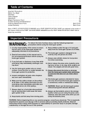
... Important Precautions 2 Before You Begin 3 Assembly 4 Cable Diagram 19 Adjustment 20 Weight Resistance Chart 22 Trouble-shooting and Maintenance 23 Ordering Replacement Parts Back Cover Limited Warranty Back Cover Note: A PART LIST/EXPLODED DRAWING and a PART IDENTIFICATION CHART are attached to the center of all precautions. 2. Never release the press arms, butterfly arms, leg lever, lat bar or ab strap while weights are using the butterfly arms. WARNING: Before beginning this manual. Do not use these attachments. 14. It is especially important for...
... Important Precautions 2 Before You Begin 3 Assembly 4 Cable Diagram 19 Adjustment 20 Weight Resistance Chart 22 Trouble-shooting and Maintenance 23 Ordering Replacement Parts Back Cover Limited Warranty Back Cover Note: A PART LIST/EXPLODED DRAWING and a PART IDENTIFICATION CHART are attached to the center of all precautions. 2. Never release the press arms, butterfly arms, leg lever, lat bar or ab strap while weights are using the butterfly arms. WARNING: Before beginning this manual. Do not use these attachments. 14. It is especially important for...
English Manual
Page 3
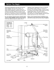
...; 230 Home Gym System (see the front cover of the body. Customer Service Department toll-free at 1-800-9993756, Monday through Friday, 6 a.m. To help us assist you for selecting the innovative and versatile HEALTHRIDER¨ 230 Home Gym System. Press Arm Adjustment Cam Shroud Covering Weight Stack Lat Bar High Pulley Station Press Arm Adjustment Knob Press Arms Weight Stack Leg Lever Low Pulley Station Foot Plate Seat Backrest 3 Adjustment Disc Butterfly Arm Backrest Adjustment Knob For your benefit, read this manual). until 6 p.m. The model number...
...; 230 Home Gym System (see the front cover of the body. Customer Service Department toll-free at 1-800-9993756, Monday through Friday, 6 a.m. To help us assist you for selecting the innovative and versatile HEALTHRIDER¨ 230 Home Gym System. Press Arm Adjustment Cam Shroud Covering Weight Stack Lat Bar High Pulley Station Press Arm Adjustment Knob Press Arms Weight Stack Leg Lever Low Pulley Station Foot Plate Seat Backrest 3 Adjustment Disc Butterfly Arm Backrest Adjustment Knob For your benefit, read this manual). until 6 p.m. The model number...
English Manual
Page 4
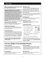
... completed successfully by assembling the base and the upright frames that connect the moving parts will take the time to the frame. Giving Yourself a Good Start Before you have included a PART IDENTIFICATION CHART located in the shipping box. Cable Assembly Completes the cables and pulleys that serve as possible, we have a socket set, a set of our products can be attached to complete the steps outlined here. Lining...
... completed successfully by assembling the base and the upright frames that connect the moving parts will take the time to the frame. Giving Yourself a Good Start Before you have included a PART IDENTIFICATION CHART located in the shipping box. Cable Assembly Completes the cables and pulleys that serve as possible, we have a socket set, a set of our products can be attached to complete the steps outlined here. Lining...
English Manual
Page 5
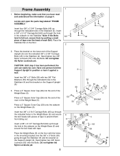
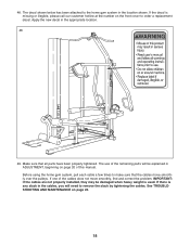
...) onto the Bolts. CAUTION: Until step 3 has been performed, the unit can easily tip over the indicated 3/8Ó x 2 3/4Ó Carriage Bolts (45) in the sidearm on the lower end of the Weight Base (5). Do not tighten the Nylon Locknuts yet. Hand tighten two 3/8Ó Nylon Locknuts (50) onto the Bolts. Locate and open the parts bag labeled ÒFRAME ASSEMBLY.Ó Insert...
...) onto the Bolts. CAUTION: Until step 3 has been performed, the unit can easily tip over the indicated 3/8Ó x 2 3/4Ó Carriage Bolts (45) in the sidearm on the lower end of the Weight Base (5). Do not tighten the Nylon Locknuts yet. Hand tighten two 3/8Ó Nylon Locknuts (50) onto the Bolts. Locate and open the parts bag labeled ÒFRAME ASSEMBLY.Ó Insert...
English Manual
Page 8
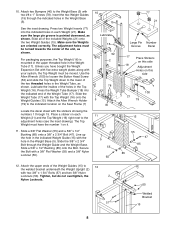
...). The adjustment holes must be moved. For packaging purposes, the Top Weight (16) is pointed downward, as shown. Lubricate the insides of the unit, as shown. Press the Weight Tube Bumper (18) into the indicated holes in the indicated Weight Guide (15) with the stickers showing the numbers 1 through 15. Attach the Allen Wrench Holder (79) to the indicated location on...
...). The adjustment holes must be moved. For packaging purposes, the Top Weight (16) is pointed downward, as shown. Lubricate the insides of the unit, as shown. Press the Weight Tube Bumper (18) into the indicated holes in the indicated Weight Guide (15) with the stickers showing the numbers 1 through 15. Attach the Allen Wrench Holder (79) to the indicated location on...

English Manual
Page 9
... 34 14 81 26 Adjustment Holes Crossbar 88 Lubricate 28 88 10 31 82 29 28 Assemble the Left Adjustment Disc (26) in its entire length. Slide a Butterfly Foam Pad (29) onto the indicated end of each press arm on the crossbar attached to the Main Upright (1). Make sure the teeth on the press arms. Locate the Press Adjustment Frame (14). 14. Hold...
... 34 14 81 26 Adjustment Holes Crossbar 88 Lubricate 28 88 10 31 82 29 28 Assemble the Left Adjustment Disc (26) in its entire length. Slide a Butterfly Foam Pad (29) onto the indicated end of each press arm on the crossbar attached to the Main Upright (1). Make sure the teeth on the press arms. Locate the Press Adjustment Frame (14). 14. Hold...
English Manual
Page 10
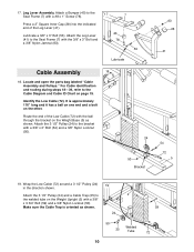
... routing during steps 18Ñ39, refer to 2 the welded tube on page 19. Attach a Bumper (40) to the Seat Frame (7) with a 3/8Ó x 2Ó Bolt (54) and a 3/8Ó Nylon Locknut (50). 24 50 Bracket 63 28 41 54 72 5 19. Attach the 3 1/2Ó Pulley (24) and a Cable Trap (25) to the Cable Diagram and Cable ID Chart on the Weight Upright (2) with a #8 x 1Ó Screw (78). 7 Press...
... routing during steps 18Ñ39, refer to 2 the welded tube on page 19. Attach a Bumper (40) to the Seat Frame (7) with a 3/8Ó x 2Ó Bolt (54) and a 3/8Ó Nylon Locknut (50). 24 50 Bracket 63 28 41 54 72 5 19. Attach the 3 1/2Ó Pulley (24) and a Cable Trap (25) to the Cable Diagram and Cable ID Chart on the Weight Upright (2) with a #8 x 1Ó Screw (78). 7 Press...
English Manual
Page 11
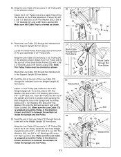
... slot in the Weight Upright (2). Wrap the Low Cable (72) around the Pulley in the direction shown. Locate the Small Pulley Frame (22) and remove both of the Low Cable (72) through the indicated slot in the Support Upright (3) from below . 21 Route Cable Through Slot From Above 72 3 54 22. Feed the bolt at the end of the pre-assembled 3 1/2Ó Pulleys (24). To do...
... slot in the Weight Upright (2). Wrap the Low Cable (72) around the Pulley in the direction shown. Locate the Small Pulley Frame (22) and remove both of the Low Cable (72) through the indicated slot in the Support Upright (3) from below . 21 Route Cable Through Slot From Above 72 3 54 22. Feed the bolt at the end of the pre-assembled 3 1/2Ó Pulleys (24). To do...

English Manual
Page 13
... the direction shown and route it back down through the Pulley, Cable Trap and riser. Do not use a 3/8Ó Nylon Locknut unless the Bolt slides out during the following step. 31 73 Riser 25 24 46 5 13 Make sure the Cable Trap is on the Stabilizer (4) with a 3/8Ó Nylon Locknut (50). 28. Make sure the Pulley you are attaching in step...
... the direction shown and route it back down through the Pulley, Cable Trap and riser. Do not use a 3/8Ó Nylon Locknut unless the Bolt slides out during the following step. 31 73 Riser 25 24 46 5 13 Make sure the Cable Trap is on the Stabilizer (4) with a 3/8Ó Nylon Locknut (50). 28. Make sure the Pulley you are attaching in step...

English Manual
Page 14
..., drawing 33A shows some parts removed. 14 35A 50 25 24 Welded Tube 56 B 73 Mount Pulley Here 6 Attach the 3 1/2Ó Pulley (24) to the lower half of the Pulleys attached to the sidearm on the Weight Base (5) by sliding the Cable Trap and Pulley onto the 3/8Ó x 4 3/4Ó Bolt (46) attached in the direction shown. Attach the 3 1/2Ó Pulley (24) and a Cable Trap (25) to the...
..., drawing 33A shows some parts removed. 14 35A 50 25 24 Welded Tube 56 B 73 Mount Pulley Here 6 Attach the 3 1/2Ó Pulley (24) to the lower half of the Pulleys attached to the sidearm on the Weight Base (5) by sliding the Cable Trap and Pulley onto the 3/8Ó x 4 3/4Ó Bolt (46) attached in the direction shown. Attach the 3 1/2Ó Pulley (24) and a Cable Trap (25) to the...

English Manual
Page 15
... free end of clarity, some parts have 92 25 been removed from the drawing. 39. 36. Wrap the Butterfly Cable (92) around a 3 1/2Ó Pulley 38 (24) in the leg 36 of the Seat Frame (7). 7 41 Attach the closed loop at the end of the High Cable (73) to 50 the lower half of the Butterfly Cable (92) to the 39 Right Adjustment...
... free end of clarity, some parts have 92 25 been removed from the drawing. 39. 36. Wrap the Butterfly Cable (92) around a 3 1/2Ó Pulley 38 (24) in the leg 36 of the Seat Frame (7). 7 41 Attach the closed loop at the end of the High Cable (73) to 50 the lower half of the Butterfly Cable (92) to the 39 Right Adjustment...

English Manual
Page 16
... Cables and the Pulleys move smoothly. Identify the Right Backrest Frame (101) and the Left Backrest Frame (37) by looking at the end of the Low Cable is one of the Backrest Frames. Attach the Backrest (12) to the indicated hole in the Seat Frame (7) with a 3/8Ó x 6 1/2Ó Bolt (65) and a 3/8Ó Nylon Locknut (50). Locate and open the parts...
... Cables and the Pulleys move smoothly. Identify the Right Backrest Frame (101) and the Left Backrest Frame (37) by looking at the end of the Low Cable is one of the Backrest Frames. Attach the Backrest (12) to the indicated hole in the Seat Frame (7) with a 3/8Ó x 6 1/2Ó Bolt (65) and a 3/8Ó Nylon Locknut (50). Locate and open the parts...

English Manual
Page 17
... is the one Pad Tube (42) into the Leg Lever (41). Do not tighten the Bolts yet. 45 80 Bracket 80 46. Top Bar 80 80 80 80 80 36 35 17 Go back and fully tighten all of the 1/4Ó x 5/8Ó Bolts (80) used to the end of the Pad Tube. 44. ...Attach both Shrouds (35, 36) to attach both Shrouds (35, 36). Slide a Foam Roller (30) onto each end of 47 2 the weight stack. Insert one that does not have a slot in steps 45 and 46 to attach the Left Shroud (35) on the Weight Upright (2) with two 1/4Ó x 5/8Ó Bolts (80). Insert the other Pad Tube (42) into the Seat...
... is the one Pad Tube (42) into the Leg Lever (41). Do not tighten the Bolts yet. 45 80 Bracket 80 46. Top Bar 80 80 80 80 80 36 35 17 Go back and fully tighten all of the 1/4Ó x 5/8Ó Bolts (80) used to the end of the Pad Tube. 44. ...Attach both Shrouds (35, 36) to attach both Shrouds (35, 36). Slide a Foam Roller (30) onto each end of 47 2 the weight stack. Insert one that does not have a slot in steps 45 and 46 to attach the Left Shroud (35) on the Weight Upright (2) with two 1/4Ó x 5/8Ó Bolts (80). Insert the other Pad Tube (42) into the Seat...
English Manual
Page 18
... parts will need to the home gym system in ADJUSTMENT, beginning on the front cover to make sure that all parts have been properly tightened. The decal shown below has been attached to remove the slack by tightening the cables. The use of the cables does not move smoothly over the pulleys. See TROUBLESHOOTING AND MAINTENANCE on page 23. 18 If there is any slack in the appropriate location...
... parts will need to the home gym system in ADJUSTMENT, beginning on the front cover to make sure that all parts have been properly tightened. The decal shown below has been attached to remove the slack by tightening the cables. The use of the cables does not move smoothly over the pulleys. See TROUBLESHOOTING AND MAINTENANCE on page 23. 18 If there is any slack in the appropriate location...
English Manual
Page 20
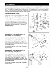
.... Use the WEIGHT RESISTANCE CHART on page 22 to find the approximate amount of resistance at each part of the home gym system can be reduced. Adjust the length of the Chain between the Lat Bar and the High Cable so the Lat Bar is performed, the effectiveness of the exercise will go. Note: Due to the cables and pulleys, the amount of resistance at each exercise. Attaching the Lat Bar, Ankle Strap...
.... Use the WEIGHT RESISTANCE CHART on page 22 to find the approximate amount of resistance at each part of the home gym system can be reduced. Adjust the length of the Chain between the Lat Bar and the High Cable so the Lat Bar is performed, the effectiveness of the exercise will go. Note: Due to the cables and pulleys, the amount of resistance at each exercise. Attaching the Lat Bar, Ankle Strap...
English Manual
Page 22
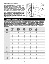
... the 10 lb. This chart shows the resistance for use during regular exercises. ask for use when the Butterfly Arms are stored in the horizontal position as a separate purchase; weight plates. Weight Plates Press Arm (lbs.) Lower Pulley (lbs.) Upper Pulley (lbs.) Butterfly (one of the adjustment holes in individual weight plates as well as friction between the cables, pulleys, and weight guides. Release the Adjustment Knob and let it snap...
... the 10 lb. This chart shows the resistance for use during regular exercises. ask for use when the Butterfly Arms are stored in the horizontal position as a separate purchase; weight plates. Weight Plates Press Arm (lbs.) Lower Pulley (lbs.) Upper Pulley (lbs.) Butterfly (one of the adjustment holes in individual weight plates as well as friction between the cables, pulleys, and weight guides. Release the Adjustment Knob and let it snap...
English Manual
Page 23
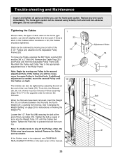
... and Maintenance Inspect and tighten all parts each time you use solvents. Replace any worn parts immediately. Tightening the Cables 1 Woven cable, the type of the 3 1/2Ó Pulleys (24) attached to the second adjustment hole. Slack can be cleaned using a damp cloth and mild non-abrasive detergent. If the Cables are tight. See ÒChanging the Weight SettingÓ on page 20 for instructions on the back cover of turns...
... and Maintenance Inspect and tighten all parts each time you use solvents. Replace any worn parts immediately. Tightening the Cables 1 Woven cable, the type of the 3 1/2Ó Pulleys (24) attached to the second adjustment hole. Slack can be cleaned using a damp cloth and mild non-abrasive detergent. If the Cables are tight. See ÒChanging the Weight SettingÓ on page 20 for instructions on the back cover of turns...
English Manual
Page 27
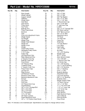
... Key No. Main Upright 53 9 Weight Upright 54 6 Support Upright 55 28 Stabilizer 56 1 Weight Base 57 4 Seat Base 58 4 Seat Frame 59 2 Press frame 60 1 Top Frame 61 1 Butterfly Arm 62 2 Press Frame Knob 63 4 Backrest 64 2 Seat 65 2 Press Arm Adjustment Frame 66 2 Weight Guide 67 1 Top Weight 68 1 Weight Tube 69 2 Weight Tube Bumper 70 2 Weight Pin 71 4 Weight Cover 72 1 Weight 73 1 Small Pulley Frame 74 4 Adjustable Pulley Frame 75 1 3 1/2Ó Pulley 76 1 Cable Trap 77 28 Left Adjustment...
... Key No. Main Upright 53 9 Weight Upright 54 6 Support Upright 55 28 Stabilizer 56 1 Weight Base 57 4 Seat Base 58 4 Seat Frame 59 2 Press frame 60 1 Top Frame 61 1 Butterfly Arm 62 2 Press Frame Knob 63 4 Backrest 64 2 Seat 65 2 Press Arm Adjustment Frame 66 2 Weight Guide 67 1 Top Weight 68 1 Weight Tube 69 2 Weight Tube Bumper 70 2 Weight Pin 71 4 Weight Cover 72 1 Weight 73 1 Small Pulley Frame 74 4 Adjustable Pulley Frame 75 1 3 1/2Ó Pulley 76 1 Cable Trap 77 28 Left Adjustment...
English Manual
Page 29
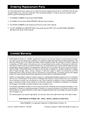
... freight and other warranty beyond that specifically set forth herein. Some states do not allow the exclusion or limitation of the product (HEALTHRIDER¨ 230 Home Gym System). 3. You may not apply to the original purchaser. Ordering Replacement Parts To order replacement parts, simply call our Customer Service Department toll-free at the center of this manual). The KEY NUMBER and DESCRIPTION of merchantability or fitness for which...
... freight and other warranty beyond that specifically set forth herein. Some states do not allow the exclusion or limitation of the product (HEALTHRIDER¨ 230 Home Gym System). 3. You may not apply to the original purchaser. Ordering Replacement Parts To order replacement parts, simply call our Customer Service Department toll-free at the center of this manual). The KEY NUMBER and DESCRIPTION of merchantability or fitness for which...

