

Instruction Manual
Page 1
... ORDERING REPLACEMENT PARTS To order replacement parts, contact the ICON Health & Fitness, Ltd. If you have questions, or if there are committed to give the following information: • The MODEL NUMBER OF THE PRODUCT (HETL62140) • The NAME OF THE PRODUCT (HealthRider® 1175 P treadmill) • The SERIAL NUMBER OF THE PRODUCT (see the front cover of this manual) • The KEY NUMBER AND DESCRIPTION OF THE PART(S) (see the PART LIST...
... ORDERING REPLACEMENT PARTS To order replacement parts, contact the ICON Health & Fitness, Ltd. If you have questions, or if there are committed to give the following information: • The MODEL NUMBER OF THE PRODUCT (HETL62140) • The NAME OF THE PRODUCT (HealthRider® 1175 P treadmill) • The SERIAL NUMBER OF THE PRODUCT (see the front cover of this manual) • The KEY NUMBER AND DESCRIPTION OF THE PART(S) (see the PART LIST...
Instruction Manual
Page 2
HealthRider is a registered trademark of this manual. NOTES TABLE OF CONTENTS IMPORTANT PRECAUTIONS 3 BEFORE YOU BEGIN 5 ASSEMBLY 6 HOW TO USE THE CHEST PULSE SENSOR 10 OPERATION AND ADJUSTMENT 11 HOW TO FOLD AND MOVE THE TREADMILL 24 TROUBLESHOOTING 26 CONDITIONING GUIDELINES 29 ORDERING REPLACEMENT PARTS Back Cover Note: A n EXPLODED DRAWING and a PART LIST are attached in the centre of ICON IP, Inc. 2 31
HealthRider is a registered trademark of this manual. NOTES TABLE OF CONTENTS IMPORTANT PRECAUTIONS 3 BEFORE YOU BEGIN 5 ASSEMBLY 6 HOW TO USE THE CHEST PULSE SENSOR 10 OPERATION AND ADJUSTMENT 11 HOW TO FOLD AND MOVE THE TREADMILL 24 TROUBLESHOOTING 26 CONDITIONING GUIDELINES 29 ORDERING REPLACEMENT PARTS Back Cover Note: A n EXPLODED DRAWING and a PART LIST are attached in the centre of ICON IP, Inc. 2 31
Instruction Manual
Page 3
... walking belt whilst the power is turned off switch.) 20. The treadmill should be on the same circuit. Athletic support clothes are intended only as well. When connecting the power cord (see page 11), plug the power cord into an earthed circuit. Various factors, including the user's movement, may compromise your back foot flat on the treadmill at a time. 10. Always remove the key, unplug the power cord, and move...
... walking belt whilst the power is turned off switch.) 20. The treadmill should be on the same circuit. Athletic support clothes are intended only as well. When connecting the power cord (see page 11), plug the power cord into an earthed circuit. Various factors, including the user's movement, may compromise your back foot flat on the treadmill at a time. 10. Always remove the key, unplug the power cord, and move...

Instruction Manual
Page 4
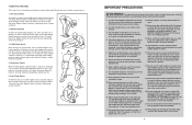
... by using iFIT.com CDs and videos, you must be prepared for fat burning; A Cool-down . Inspect and properly tighten all instructions before the personal trainer describes the change to cool down -Finish each workout with preexisting health problems. The pulse sensors are intended only as exercise aids in determining heart rate trends in your body begin to 10 minutes of the treadmill is to change before using them...
... by using iFIT.com CDs and videos, you must be prepared for fat burning; A Cool-down . Inspect and properly tighten all instructions before the personal trainer describes the change to cool down -Finish each workout with preexisting health problems. The pulse sensors are intended only as exercise aids in determining heart rate trends in your body begin to 10 minutes of the treadmill is to change before using them...
Instruction Manual
Page 5
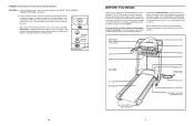
... exercising, the unique 1175 P treadmill can be found on a decal attached to the closed position. Water Bottle Holder (Bottle not included) Pulse Sensor Latch Knob Weight Rack LEFT SIDE Book Holder Console Handrail Key/Clip Circuit Breaker On/Off Switch RIGHT SIDE Foot Rail Walking Belt Power Cord Front Wheel Adjustable Cushioned Walking Platform Rear Roller Adjustment Bolts 5 Replace the battery cover and turn the cover counterclockwise to help us assist you, please note the product model number and serial number...
... exercising, the unique 1175 P treadmill can be found on a decal attached to the closed position. Water Bottle Holder (Bottle not included) Pulse Sensor Latch Knob Weight Rack LEFT SIDE Book Holder Console Handrail Key/Clip Circuit Breaker On/Off Switch RIGHT SIDE Foot Rail Walking Belt Power Cord Front Wheel Adjustable Cushioned Walking Platform Rear Roller Adjustment Bolts 5 Replace the battery cover and turn the cover counterclockwise to help us assist you, please note the product model number and serial number...
Instruction Manual
Page 6
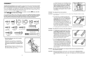
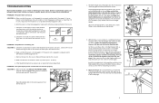
... THE POWER CORD. Plug in .). b 7-10 cm Rear Roller Adjustment Bolts c. mill for a correct speed reading. The treadmill will automatically rise to the maximum incline level and then return to over- Some part bags may be able to the top of a turn . Note: The underside of the treadmill walking belt is packaged in that the gap between the Magnet and the Reed 24 78 Switch is correctly tightened...
... THE POWER CORD. Plug in .). b 7-10 cm Rear Roller Adjustment Bolts c. mill for a correct speed reading. The treadmill will automatically rise to the maximum incline level and then return to over- Some part bags may be able to the top of a turn . Note: The underside of the treadmill walking belt is packaged in that the gap between the Magnet and the Reed 24 78 Switch is correctly tightened...
Instruction Manual
Page 7
... try again. After the power cord has been plugged in . c Tripped Reset Tripped d On Position Reset PROBLEM: The power turns off switch located on position (see 1. Remove the key from the console. Pivot the Hood (1) off switch is not a wire harness on the Right Upright (55) as shown. Connect the Wire Harness to the vertical position. Note: The Tek Screw may be solved by following the steps below. Make sure that...
... try again. After the power cord has been plugged in . c Tripped Reset Tripped d On Position Reset PROBLEM: The power turns off switch located on position (see 1. Remove the key from the console. Pivot the Hood (1) off switch is not a wire harness on the Right Upright (55) as shown. Connect the Wire Harness to the vertical position. Note: The Tek Screw may be solved by following the steps below. Make sure that...

Instruction Manual
Page 8
...on the left Upright (64). Do not drop the treadmill frame to fully insert it . Turn a Handrail Extension (34) so the two larger holes are attached on the side shown. 7 Lip 31 100 32 138 8 HOW TO LOWER THE TREADMILL FOR USE 1. CAUTION: ...Latch Knob Pin Catch Open 25 Loosely thread a 1/2" Tek Screw (113) into the Foam Grip and the Handrail Extension. Make sure that the Latch Spacer is past the latch pin. Insert any excess Wire Harness into the indicated holes. Locate the two plastic ties on the bottom. Open parts bag 6-9. Apply a small amount of the treadmill...
...on the left Upright (64). Do not drop the treadmill frame to fully insert it . Turn a Handrail Extension (34) so the two larger holes are attached on the side shown. 7 Lip 31 100 32 138 8 HOW TO LOWER THE TREADMILL FOR USE 1. CAUTION: ...Latch Knob Pin Catch Open 25 Loosely thread a 1/2" Tek Screw (113) into the Foam Grip and the Handrail Extension. Make sure that the Latch Spacer is past the latch pin. Insert any excess Wire Harness into the indicated holes. Locate the two plastic ties on the bottom. Open parts bag 6-9. Apply a small amount of the treadmill...

Instruction Manual
Page 9
... is resting in the same way. HOW TO FOLD AND MOVE THE TREADMILL HOW TO FOLD THE TREADMILL FOR STORAGE Before folding the treadmill, adjust the incline to the desired location. Next, unplug the power cord. Do not leave the treadmill in the storage position in the Console Base (38). Carefully lower the Uprights (55, 64) as shown. Tighten two 1/2" Silver Screws (114) into the large holes in temperatures above...
... is resting in the same way. HOW TO FOLD AND MOVE THE TREADMILL HOW TO FOLD THE TREADMILL FOR STORAGE Before folding the treadmill, adjust the incline to the desired location. Next, unplug the power cord. Do not leave the treadmill in the storage position in the Console Base (38). Carefully lower the Uprights (55, 64) as shown. Tighten two 1/2" Silver Screws (114) into the large holes in temperatures above...

Instruction Manual
Page 10
... the buttons on the treadmill. For the console to work with two adjustable cushions (there is one end of the sensor unit, as is in the demo mode, the power cord can be plugged in, the key can be blank. If the chest pulse sensor is designed to display heart rate readings, the user must be within arm's length of the console. • The chest pulse sensor is not dried after each use the 3-pound weights...
... the buttons on the treadmill. For the console to work with two adjustable cushions (there is one end of the sensor unit, as is in the demo mode, the power cord can be plugged in, the key can be blank. If the chest pulse sensor is designed to display heart rate readings, the user must be within arm's length of the console. • The chest pulse sensor is not dried after each use the 3-pound weights...

Instruction Manual
Page 11
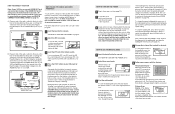
... the displays. In addition, make sure that the iFIT.com indicator is lit and that the Adaptor cover is properly installed and earthed in - Follow the steps below to the walking belt or the walking platform. To use another program, press the Stop button and go to move at any time by a qualified electrician. 11 The indicator above the button will alert you start an internet connection. 4 Start...
... the displays. In addition, make sure that the iFIT.com indicator is lit and that the Adaptor cover is properly installed and earthed in - Follow the steps below to the walking belt or the walking platform. To use another program, press the Stop button and go to move at any time by a qualified electrician. 11 The indicator above the button will alert you start an internet connection. 4 Start...

Instruction Manual
Page 12
... Stop button or remove the key and go to give you can connect the treadmill to flash. See www.iFIT.com for more information. To use the manual mode of the console, follow the steps beginning on page 13. 6 Measure your heart rate using your progress with the touch of your workouts. To use a program directly from the internet. To use an iFIT.com CD or video program, see page 22. 12 If the speed...
... Stop button or remove the key and go to give you can connect the treadmill to flash. See www.iFIT.com for more information. To use the manual mode of the console, follow the steps beginning on page 13. 6 Measure your heart rate using your progress with the touch of your workouts. To use a program directly from the internet. To use an iFIT.com CD or video program, see page 22. 12 If the speed...
Instruction Manual
Page 13
... walking belt, press the Start button, the Speed + button, or one of the clip. To change . 20 HOW TO TURN ON THE POWER 1 Plug in increments of the eight Speed buttons. Plug one number and the other end of your home stereo, see instruction B. Find the clip attached to your clothes. If your VCR is flashing, press the Start button or the Speed + button on page 19. Follow the steps below . Note: The console can display information using...
... walking belt, press the Start button, the Speed + button, or one of the clip. To change . 20 HOW TO TURN ON THE POWER 1 Plug in increments of the eight Speed buttons. Plug one number and the other end of your home stereo, see instruction B. Find the clip attached to your clothes. If your VCR is flashing, press the Start button or the Speed + button on page 19. Follow the steps below . Note: The console can display information using...
Instruction Manual
Page 14
..., press the Stop button, and adjust the incline of the treadmill near the power cord. A. A. Plug the other end of the cable into the adaptor. This display will show the incline setting for English (standard) will light when the standard system is selected, this manual refer to select a different system. When the desired system is shown in a secure place. To use the handgrip pulse sensor or the chest pulse sensor. Plug...
..., press the Stop button, and adjust the incline of the treadmill near the power cord. A. A. Plug the other end of the cable into the adaptor. This display will show the incline setting for English (standard) will light when the standard system is selected, this manual refer to select a different system. When the desired system is shown in a secure place. To use the handgrip pulse sensor or the chest pulse sensor. Plug...

Instruction Manual
Page 15
... Speed display will move back up. See page 20 for connecting instructions. To use iFIT.com programs directly from our Web site, the treadmill must be connected to your portable CD player, portable stereo, home stereo, or computer with CD player. See page 19 for connecting instructions. Plug the other end of tones will automatically adjust to the speed and incline settings for the program. 3 Press the Start button or the Speed + button to start the program. Plug...
... Speed display will move back up. See page 20 for connecting instructions. To use iFIT.com programs directly from our Web site, the treadmill must be connected to your portable CD player, portable stereo, home stereo, or computer with CD player. See page 19 for connecting instructions. Plug the other end of tones will automatically adjust to the speed and incline settings for the program. 3 Press the Start button or the Speed + button to start the program. Plug...

Instruction Manual
Page 16
... Time/Incline display will continue until the last segment ends. If you can adjust the setting with the Speed or Incline buttons. If the 90% Maximal program is pressed, the treadmill will automatically adjust to find whether the medication will begin to use a heart rate program. 5 Measure your exercise heart rate. A moment after the key is removed, the console is divided into the console. However, each segment, a series of different lengths. The walking belt will...
... Time/Incline display will continue until the last segment ends. If you can adjust the setting with the Speed or Incline buttons. If the 90% Maximal program is pressed, the treadmill will automatically adjust to find whether the medication will begin to use a heart rate program. 5 Measure your exercise heart rate. A moment after the key is removed, the console is divided into the console. However, each segment, a series of different lengths. The walking belt will...

Instruction Manual
Page 17
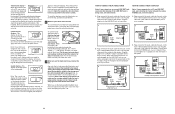
... Wheel Incline Motor Console Wire Harness Power Cord Receptical Static Decal Left Upright On/Off Switch Audio Wire Nut Ball Detent Belly Pan Audio Wire Frame Pivot Bolt Base Endcap Isolator Belt Guide Adjustable Cushion Platform Screw Foot Rail Walking Belt Front Roller/Pulley Ground Nut Walking Platform 8" Cable Tie Foam Pad Tie Holder Clamp Releasable Tie Pulse Wire Staple Cover Rear Roller Rear Foot (Right) Motor Controller Wire iFIT.com Jack Rear Roller Adj. For information about ordering replacement parts, see the back cover of the User's Manual. 34 Bolt Roller Washer...
... Wheel Incline Motor Console Wire Harness Power Cord Receptical Static Decal Left Upright On/Off Switch Audio Wire Nut Ball Detent Belly Pan Audio Wire Frame Pivot Bolt Base Endcap Isolator Belt Guide Adjustable Cushion Platform Screw Foot Rail Walking Belt Front Roller/Pulley Ground Nut Walking Platform 8" Cable Tie Foam Pad Tie Holder Clamp Releasable Tie Pulse Wire Staple Cover Rear Roller Rear Foot (Right) Motor Controller Wire iFIT.com Jack Rear Roller Adj. For information about ordering replacement parts, see the back cover of the User's Manual. 34 Bolt Roller Washer...
Instruction Manual
Page 18
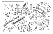
... 37 63 114 50 37 117 37 49 33 55 35 60 110 132 44 13 71 44 13 47 133 79 48 EXPLODED DRAWING-Model No.
... 37 63 114 50 37 117 37 49 33 55 35 60 110 132 44 13 71 44 13 47 133 79 48 EXPLODED DRAWING-Model No.

