
Technical Guide
Page 2
Table of Contents Safety Precautions Installation Programming Operation Programming Scenarios Disassembly/Assembly Password/Commercial Diagnostics/Troubleshooting Page 1 Page 2-14 Page 15-29 Page 30-31 Page 32 Page 33-38 Page 39-40 Page 41-48
Table of Contents Safety Precautions Installation Programming Operation Programming Scenarios Disassembly/Assembly Password/Commercial Diagnostics/Troubleshooting Page 1 Page 2-14 Page 15-29 Page 30-31 Page 32 Page 33-38 Page 39-40 Page 41-48
Technical Guide
Page 43
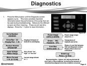
... Rev: 1.16 Product Version SP3400VSP Input Voltage Within Range Motor Current 1.1A (0-13.0A) Displays firmware of time that can be used during troubleshooting. Reads offline when not connected Event Log Press + to view information. This menu provides important information about the performance of heatsink and drive. ...83). Below are all real-time displays. Page 41 These are the different screens and their meaning. Status of com link between VSC and Hayward control. Press the „>‟ button to View By pressing the + button you will see the last 20 error and or trip ...
... Rev: 1.16 Product Version SP3400VSP Input Voltage Within Range Motor Current 1.1A (0-13.0A) Displays firmware of time that can be used during troubleshooting. Reads offline when not connected Event Log Press + to view information. This menu provides important information about the performance of heatsink and drive. ...83). Below are all real-time displays. Page 41 These are the different screens and their meaning. Status of com link between VSC and Hayward control. Press the „>‟ button to View By pressing the + button you will see the last 20 error and or trip ...

Technical Guide
Page 44
... no continuity. If there are within +/- 10% of these readings are addressed in the owners manual. There should be checked. If any of 230 VAC. Troubleshooting/Fault Codes This guide will cover only those problems with priming problems are outside limits, replace motor. All other pump problems including seals, gaskets, impellers...
... no continuity. If there are within +/- 10% of these readings are addressed in the owners manual. There should be checked. If any of 230 VAC. Troubleshooting/Fault Codes This guide will cover only those problems with priming problems are outside limits, replace motor. All other pump problems including seals, gaskets, impellers...

Technical Guide
Page 45
... of the drive. Indicates that it is within +/- 10% of 230 VAC. Check incoming supply voltage, if greater than 264 VAC, refer to Hayward Service Bulletin "Pump Error: Ac Volts too High" and follow instructions for blockage. Indicates that it is within +/- 10% of 230 VAC. If...error still occurs, replace drive. If line voltage is too low. If line voltage is correct and error still occurs after registry change . Troubleshooting/Fault Codes Code/Fault Drive Error! Check incoming line voltage (page 4) and verify that the incoming line voltage has dropped below 185 VAC ...
... of the drive. Indicates that it is within +/- 10% of 230 VAC. Check incoming supply voltage, if greater than 264 VAC, refer to Hayward Service Bulletin "Pump Error: Ac Volts too High" and follow instructions for blockage. Indicates that it is within +/- 10% of 230 VAC. If...error still occurs, replace drive. If line voltage is too low. If line voltage is correct and error still occurs after registry change . Troubleshooting/Fault Codes Code/Fault Drive Error! Check incoming line voltage (page 4) and verify that the incoming line voltage has dropped below 185 VAC ...

Technical Guide
Page 46
...run Standalone. If no continuity. If error still exists remove the Blue, Black and Red wires (page 4) from lead to a Hayward/Goldline Controller, disconnect the com ground wire between interface and drive. Indications Indicates that the drive was not able to ground. Check ...to lead. Page 44 If error still exists remove all (0) check connection between terminal 1 with EcoStar and terminal 4 with Hayward/Goldline Control (page 10). If they are connected correctly (page 10). If pump is displayed. Troubleshooting/Fault Codes Code/Fault Drive Error Drive failed to Start.
...run Standalone. If no continuity. If error still exists remove the Blue, Black and Red wires (page 4) from lead to a Hayward/Goldline Controller, disconnect the com ground wire between interface and drive. Indications Indicates that the drive was not able to ground. Check ...to lead. Page 44 If error still exists remove all (0) check connection between terminal 1 with EcoStar and terminal 4 with Hayward/Goldline Control (page 10). If they are connected correctly (page 10). If pump is displayed. Troubleshooting/Fault Codes Code/Fault Drive Error Drive failed to Start.
Technical Guide
Page 47
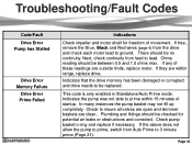
Troubleshooting/Fault Codes Code/Fault Drive Error Pump has Stalled Drive Error Memory Failure Drive Error Prime Failed Indications Check impeller and motor shaft for potential ...
Troubleshooting/Fault Codes Code/Fault Drive Error Pump has Stalled Drive Error Memory Failure Drive Error Prime Failed Indications Check impeller and motor shaft for potential ...

Technical Guide
Page 48
...emitted from the control. If not, replace motor. Troubleshooting/Fault Codes Code/Fault Indications Warning NO Comm Inspect the data wire between the control and EcoStar. If the values are correct, replace the drive. EcoStar is tripping. Contact Clemmons Tech Service for isolator. Disconnect... Blue, Black, and Red motor leads (page 4) from the display and re-connect. Disconnect the wires from drive. The breaker is connected to a GL/Hayward control. Check input wiring...
...emitted from the control. If not, replace motor. Troubleshooting/Fault Codes Code/Fault Indications Warning NO Comm Inspect the data wire between the control and EcoStar. If the values are correct, replace the drive. EcoStar is tripping. Contact Clemmons Tech Service for isolator. Disconnect... Blue, Black, and Red motor leads (page 4) from the display and re-connect. Disconnect the wires from drive. The breaker is connected to a GL/Hayward control. Check input wiring...

Technical Guide
Page 49
...in the control (page 5). Page 47 The %/rpm reading does not match between GL/Hayward control and EcoStar. Be sure EcoStar is configured for relay control (page 10) . Check comm. No connections are on the EcoStar is set to variable speed . Check the settings in the control filter configuration menu ...and set at the minimum (600rpm/17%) and the maximum (3450rpm/100%) so as to not interfere with a GL/Hayward control. Troubleshooting/Fault Codes Code/Fault Indications EcoStar is connected and configured to operate with the settings in the control (page 20...
...in the control (page 5). Page 47 The %/rpm reading does not match between GL/Hayward control and EcoStar. Be sure EcoStar is configured for relay control (page 10) . Check comm. No connections are on the EcoStar is set to variable speed . Check the settings in the control filter configuration menu ...and set at the minimum (600rpm/17%) and the maximum (3450rpm/100%) so as to not interfere with a GL/Hayward control. Troubleshooting/Fault Codes Code/Fault Indications EcoStar is connected and configured to operate with the settings in the control (page 20...

Technical Guide
Page 50
... control are connected in the EcoStar does not work . When a command is wired and set to the pump, the EcoStar interface reads "Remote Stop Engaged". Page 48 Troubleshooting/Fault Codes Code/Fault Indications The freeze protection in the EcoStar to the comm. The Speed... buttons and Quick Clean buttons on X-10. This indicates that the comm. The EcoStar is sent to operate via the GL/Hayward...
... control are connected in the EcoStar does not work . When a command is wired and set to the pump, the EcoStar interface reads "Remote Stop Engaged". Page 48 Troubleshooting/Fault Codes Code/Fault Indications The freeze protection in the EcoStar to the comm. The Speed... buttons and Quick Clean buttons on X-10. This indicates that the comm. The EcoStar is sent to operate via the GL/Hayward...


