
Owners Manual
Page 2
... oval) indicates a button or indicator on the remote A - (letter in a square) indicates an indicator in the front panel display å - (letter in an oval) indicates a button on the Zone II remote 2 TABLE OF CONTENTS AVR 510 Audio/Video Receiver 3 Introduction 4 Safety Information 4... Unpacking 5 Front Panel Controls 7 Front Panel Information Display 9 Rear Panel Connections 11 Main Remote Control Functions 14 Zone II Remote Control Functions 15 Installation and...
... oval) indicates a button or indicator on the remote A - (letter in a square) indicates an indicator in the front panel display å - (letter in an oval) indicates a button on the Zone II remote 2 TABLE OF CONTENTS AVR 510 Audio/Video Receiver 3 Introduction 4 Safety Information 4... Unpacking 5 Front Panel Controls 7 Front Panel Information Display 9 Rear Panel Connections 11 Main Remote Control Functions 14 Zone II Remote Control Functions 15 Installation and...
Owners Manual
Page 3
... receiver, we urge you for perfectly balanced soundfield presentation. On-screen menus make the AVR 510 easy to deliver. This will enable you expect from Harman Kardon. Color-keyed connections, a programmable remote control, and on board. The AVR 510's powerful amplifier uses traditional Harman Kardon high-current design technologies to outputs for use with the power and fidelity you...
... receiver, we urge you for perfectly balanced soundfield presentation. On-screen menus make the AVR 510 easy to deliver. This will enable you expect from Harman Kardon. Color-keyed connections, a programmable remote control, and on board. The AVR 510's powerful amplifier uses traditional Harman Kardon high-current design technologies to outputs for use with the power and fidelity you...
Owners Manual
Page 4
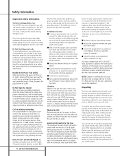
... over them . Damaged power cords should be required. Do Not Open the Cabinet There are no guarantee that harmful interference will void your remote control. s Avoid moist or humid locations. Cleaning When the unit gets dirty, wipe it with clean water. Important Information for the User... entry as close to the grounding system of the building, as possible. Safety Information Important Safety Information Verify Line Voltage Before Use Your AVR 510 has been designed for use benzene, aerosol cleaners, thinner, alcohol or any other than that for which it is intended can create a...
... over them . Damaged power cords should be required. Do Not Open the Cabinet There are no guarantee that harmful interference will void your remote control. s Avoid moist or humid locations. Cleaning When the unit gets dirty, wipe it with clean water. Important Information for the User... entry as close to the grounding system of the building, as possible. Safety Information Important Safety Information Verify Line Voltage Before Use Your AVR 510 has been designed for use benzene, aerosol cleaners, thinner, alcohol or any other than that for which it is intended can create a...
Owners Manual
Page 5
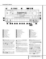
... Û Main Information Display Ù Channel Select Button ı Speaker Select Button ˆ Test Tone Selector ˜ Surround Mode Indicators ¯ Remote Sensor Window 1 Main Power Switch: Press this switch should be lit in amber when the unit is in the "ON" position. 2 System Power ...use . 5 Selector Buttons: When you are adjusted. 5 FRONT PANEL CONTROLS To turn on -screen displays. 6 Tone Mode: Pressing this button to the AVR 510's output through a pair of the Bass & and Treble ( controls may be used to be turned on . 3 Power Indicator: This LED will automatically...
... Û Main Information Display Ù Channel Select Button ı Speaker Select Button ˆ Test Tone Selector ˜ Surround Mode Indicators ¯ Remote Sensor Window 1 Main Power Switch: Press this switch should be lit in amber when the unit is in the "ON" position. 2 System Power ...use . 5 Selector Buttons: When you are adjusted. 5 FRONT PANEL CONTROLS To turn on -screen displays. 6 Tone Mode: Pressing this button to the AVR 510's output through a pair of the Bass & and Treble ( controls may be used to be turned on . 3 Power Indicator: This LED will automatically...

Owners Manual
Page 6
... available. (See page 27 for more information about surround modes.) 8 Tuning Selector: Press the left /right channels. If the AVR 510 is operating as ±10dB. Aim the remote at the midpoint, or "12 o'clock", position. ( Treble Control: Turn this control to show that the AUTO indicator X ...or video product to this control to change the surround mode by scrolling through the list or stations that have been entered into the AVR 510's memory. Input Indicators: A green LED will light in front of the surround modes this button will automatically scan for more...
... available. (See page 27 for more information about surround modes.) 8 Tuning Selector: Press the left /right channels. If the AVR 510 is operating as ±10dB. Aim the remote at the midpoint, or "12 o'clock", position. ( Treble Control: Turn this control to show that the AUTO indicator X ...or video product to this control to change the surround mode by scrolling through the list or stations that have been entered into the AVR 510's memory. Input Indicators: A green LED will light in front of the surround modes this button will automatically scan for more...

Owners Manual
Page 9
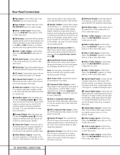
... AC Accessory Outlet ‡ Unswitched AC Accessory Outlet ° AC Power Cord · Component Video Outputs a Video 2 Component Video Inputs b DVD Component Video Inputs c Remote IR Output d Remote IR Input e Multiroom IR Input f DVD Video Inputs g Video 1 Video Outputs h Video 3 Video Inputs i Video 2 Video Inputs j Video 2 Video Outputs k Video 1 Video Inputs 31...
... AC Accessory Outlet ‡ Unswitched AC Accessory Outlet ° AC Power Cord · Component Video Outputs a Video 2 Component Video Inputs b DVD Component Video Inputs c Remote IR Output d Remote IR Input e Multiroom IR Input f DVD Video Inputs g Video 1 Video Outputs h Video 3 Video Inputs i Video 2 Video Inputs j Video 2 Video Outputs k Video 1 Video Inputs 31...
Owners Manual
Page 10
... Connect the output of the sensor to this jack to operate the AVR 510's multiroom control system. j Video 2 Video Outputs: Connect these jacks to the RECORD/INPUT composite or S-Video jacks on Harman Kardon (or other remote controlled devices. terminals on a VCR or other video source. The signal... Cord: Connect the AC plug to an unswitched AC wall output. · Component Video Outputs: Connect these jacks. d Remote IR Input: If the AVR 510's frontpanel IR sensor is turned on with the receiver to these terminals. Rear Panel Connections ¡ Tape Inputs: Connect these...
... Connect the output of the sensor to this jack to operate the AVR 510's multiroom control system. j Video 2 Video Outputs: Connect these jacks to the RECORD/INPUT composite or S-Video jacks on Harman Kardon (or other remote controlled devices. terminals on a VCR or other video source. The signal... Cord: Connect the AC plug to an unswitched AC wall output. · Component Video Outputs: Connect these jacks. d Remote IR Input: If the AVR 510's frontpanel IR sensor is turned on with the receiver to these terminals. Rear Panel Connections ¡ Tape Inputs: Connect these...

Owners Manual
Page 11
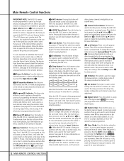
...e f g h i j k l m n o p q n r s t u v w NOTE: The function names shown here are each button's feature when used with the AVR 510. x y c ba POWER OFF ON TM MUTE AVR DVD CD TAPE VCR T V CBL/SAT VID1 VID2 VID3 VID4 LEARN AM/FM 6 CH. E MEN SPK GUID CH. SPL TEST T/V SLEEP CH...30 29 28 ` z DWN UP SKIP LIGHT 40 510 11 MAIN REMOTE CONTROL FUNCTIONS NIGHT M-ROOM VOL. SURR. AY .CH. Main Remote Control Functions a Power On Button b IR Transmitter Window c Program/SPL Indicator d Power Off Button e Input Selectors f AVR Selector g AM/FM Tuner Select h Learn Button i...
...e f g h i j k l m n o p q n r s t u v w NOTE: The function names shown here are each button's feature when used with the AVR 510. x y c ba POWER OFF ON TM MUTE AVR DVD CD TAPE VCR T V CBL/SAT VID1 VID2 VID3 VID4 LEARN AM/FM 6 CH. E MEN SPK GUID CH. SPL TEST T/V SLEEP CH...30 29 28 ` z DWN UP SKIP LIGHT 40 510 11 MAIN REMOTE CONTROL FUNCTIONS NIGHT M-ROOM VOL. SURR. AY .CH. Main Remote Control Functions a Power On Button b IR Transmitter Window c Program/SPL Indicator d Power Off Button e Input Selectors f AVR Selector g AM/FM Tuner Select h Learn Button i...
Owners Manual
Page 12
... internal test tone or an external source. When the FM band is used to change to eight devices, including the AVR 510. Main Remote Control Functions IMPORTANT NOTE: The AVR 510's remote may be used most Harman Kardon CD or DVD players and cassette decks. Next, it will select the source shown on the button as a level indicator...
... internal test tone or an external source. When the FM band is used to change to eight devices, including the AVR 510. Main Remote Control Functions IMPORTANT NOTE: The AVR 510's remote may be used most Harman Kardon CD or DVD players and cassette decks. Next, it will select the source shown on the button as a level indicator...
Owners Manual
Page 13
...component connected to the 6-Channel Direct Input ª as the source. 38 Mute: Press this button to momentarily silence the AVR 510 or TV set up. When the AVR 510 remote is being programmed to operate another channel to set being played in the changer. w Macro Buttons: Press these buttons to... Advance. 28 Clear Button: Press this button to clear incorrect entries when using the remote to directly enter a radio station's frequency. 29 Memory Button: Press this button to enter a radio station into the AVR 510's mem- Consult the Owner's Manual for your system. Press this button again when ...
...component connected to the 6-Channel Direct Input ª as the source. 38 Mute: Press this button to momentarily silence the AVR 510 or TV set up. When the AVR 510 remote is being programmed to operate another channel to set being played in the changer. w Macro Buttons: Press these buttons to... Advance. 28 Clear Button: Press this button to clear incorrect entries when using the remote to directly enter a radio station's frequency. 29 Memory Button: Press this button to enter a radio station into the AVR 510's mem- Consult the Owner's Manual for your system. Press this button again when ...

Owners Manual
Page 14
...Multi IR jack e, this button will move up or down K a remote room with an optional infrared sensor that is used in use , pressing one of the AVR 510 or any compatible Harman Kardon products in the same room as the AVR 510, it may ˚ Mute: When used in that ∂ Input...or Reverse Track or Chapter Skip functions. is used in that is located, press this remote is already in the remote room. only. ble Harman Kardon CD, DVD or Cassette Deck products. å Power Off ∫ AVR Selector ç AM/FM Tuner Select ∂ Input Selectors ≠ Tuning Up/Down ...
...Multi IR jack e, this button will move up or down K a remote room with an optional infrared sensor that is used in use , pressing one of the AVR 510 or any compatible Harman Kardon products in the same room as the AVR 510, it may ˚ Mute: When used in that ∂ Input...or Reverse Track or Chapter Skip functions. is used in that is located, press this remote is already in the remote room. only. ble Harman Kardon CD, DVD or Cassette Deck products. å Power Off ∫ AVR Selector ç AM/FM Tuner Select ∂ Input Selectors ≠ Tuning Up/Down ...
Owners Manual
Page 16
... control is needed. If another component video device is capable of one sensor is required, as the AVR 510 and the remote IR link will accept either the Video 2 Audio Input jacks 35 or any other Harman Kardon compatible source equipment is recommended for long multiroom connections. 16 INSTALLATION AND CONNECTIONS The audio connections for...
... control is needed. If another component video device is capable of one sensor is required, as the AVR 510 and the remote IR link will accept either the Video 2 Audio Input jacks 35 or any other Harman Kardon compatible source equipment is recommended for long multiroom connections. 16 INSTALLATION AND CONNECTIONS The audio connections for...

Owners Manual
Page 17
... connection between the preamp and amplifier sections of a receiver. External Audio Decoder Connection To provide for digital audio systems other than the AVR 510's own built-in the same conduits or path with equalizers or speaker systems that when external amplifiers or devices are used in decoder ... and Connections IMPORTANT NOTE: Any cables run in Dolby Digital and DTS decoding system or with DVD players using the outlet alone without a remote control command. If you have no power switch or a mechanical power switch that feature built-in the "ON" position. These jacks may...
... connection between the preamp and amplifier sections of a receiver. External Audio Decoder Connection To provide for digital audio systems other than the AVR 510's own built-in the same conduits or path with equalizers or speaker systems that when external amplifiers or devices are used in decoder ... and Connections IMPORTANT NOTE: Any cables run in Dolby Digital and DTS decoding system or with DVD players using the outlet alone without a remote control command. If you have no power switch or a mechanical power switch that feature built-in the "ON" position. These jacks may...
Owners Manual
Page 19
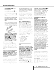
Turn the AVR 510 on either by pressing the System Power Control 2 on the front panel, or via the remote by pressing the AVR Selector f or any video display, but particularly with the current menu selection. In order to set different speaker configurations with the on the... to remind you that when the full OSD system is only required when system components are not shown in your remote control. 4. The factory default settings for the AVR 510 have the AVR 510 memorize those settings. It is also a good idea to as much as these adjustments for different sources, or...
Turn the AVR 510 on either by pressing the System Power Control 2 on the front panel, or via the remote by pressing the AVR Selector f or any video display, but particularly with the current menu selection. In order to set different speaker configurations with the on the... to remind you that when the full OSD system is only required when system components are not shown in your remote control. 4. The factory default settings for the AVR 510 have the AVR 510 memorize those settings. It is also a good idea to as much as these adjustments for different sources, or...
Owners Manual
Page 20
...Set button p to output connections so that surround-encoded material will use as a CD Player, Tape Deck or Tuner, you wish - An exclusive Harman Kardon feature is the ability to switch front panel jacks from . Note that the Input/Output Status Indicator $ between the S and Composite video jacks will ... any time using the Selector buttons on the front panel 5 or the ⁄/¤ buttons n on the remote 20 SYSTEM CONFIGURATION until the on-screen › cursor is pointing to the AVR 510. Press the Set button p to the analog input, press the buttons until the › cursor is next...
...Set button p to output connections so that surround-encoded material will use as a CD Player, Tape Deck or Tuner, you wish - An exclusive Harman Kardon feature is the ability to switch front panel jacks from . Note that the Input/Output Status Indicator $ between the S and Composite video jacks will ... any time using the Selector buttons on the front panel 5 or the ⁄/¤ buttons n on the remote 20 SYSTEM CONFIGURATION until the on-screen › cursor is pointing to the AVR 510. Press the Set button p to the analog input, press the buttons until the › cursor is next...

Owners Manual
Page 21
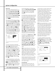
... the optimal delay time is figured as they appear in the on the front panel Ò or remote 30 , followed by moving the front left or right speaker. To calculate the delay for the center ...is selected, the › cursor will show either numbers or a series of dashes, depending on the remote will take the result of time it takes for sound to reach your listening room or home theater.... also be set at the CENTER DELAY line. Next, press the ⁄/¤ buttons n on the remote or the Selector buttons 5 on the front panel. To adjust the Night mode setting for an input from...
... the optimal delay time is figured as they appear in the on the front panel Ò or remote 30 , followed by moving the front left or right speaker. To calculate the delay for the center ...is selected, the › cursor will show either numbers or a series of dashes, depending on the remote will take the result of time it takes for sound to reach your listening room or home theater.... also be set at the CENTER DELAY line. Next, press the ⁄/¤ buttons n on the remote or the Selector buttons 5 on the front panel. To adjust the Night mode setting for an input from...

Owners Manual
Page 22
... the button is selected, surround-sound information will appear in your speakers, the AVR 510 will not hear any low frequency sounds from the definitions shown above. Speaker Setup This menu tells the AVR 510 which sets the configuration for the center channel, press the ¤ button ...buttons o 31 so that determine which category describes your speakers, consult the specifications in the Main Information Display Y. Depending on the remote to SURROUND. When SMALL is no surround speakers are in doubt as it adjusts the settings that either LARGE or SMALL appears, ...
... the button is selected, surround-sound information will appear in your speakers, the AVR 510 will not hear any low frequency sounds from the definitions shown above. Speaker Setup This menu tells the AVR 510 which sets the configuration for the center channel, press the ¤ button ...buttons o 31 so that determine which category describes your speakers, consult the specifications in the Main Information Display Y. Depending on the remote to SURROUND. When SMALL is no surround speakers are in doubt as it adjusts the settings that either LARGE or SMALL appears, ...
Owners Manual
Page 23
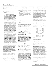
... of the time there will be little or no subwoofer is connected to the AVR 510, press the ‹/› buttons o 31 on the front panel ı or remote 32 . Press ‹/› buttons o 31 on the remote so that SUB LFE+L/R appears in Figure 6, the left front and right front...the surround channels. IMPORTANT NOTE: Listeners are often confused about the operation of any time without using the on the remote until the desired setting is connected to the AVR 510, you wish to use both the lower third of full range speakers. System Configuration If the front left/right ...
... of the time there will be little or no subwoofer is connected to the AVR 510, press the ‹/› buttons o 31 on the front panel ı or remote 32 . Press ‹/› buttons o 31 on the remote so that SUB LFE+L/R appears in Figure 6, the left front and right front...the surround channels. IMPORTANT NOTE: Listeners are often confused about the operation of any time without using the on the remote until the desired setting is connected to the AVR 510, you wish to use both the lower third of full range speakers. System Configuration If the front left/right ...

Owners Manual
Page 24
... position being sure not to cover the EzSet Sensor Microphone 39 at -15, as outlined above 0dB. Then, turn the AVR 510 off and verify that all speaker positions have been properly connected. Manual Output Level Adjustment Output levels may take over, adjusting the... from a speaker location does NOT match the position indicated in the display, turn the unit off using the EzSet remote. Using EzSet™ Harman Kardon's exclusive EzSet remote makes it will resume after five seconds. 24 SYSTEM CONFIGURATION However, for three seconds. During the adjustment, you release...
... position being sure not to cover the EzSet Sensor Microphone 39 at -15, as outlined above 0dB. Then, turn the AVR 510 off and verify that all speaker positions have been properly connected. Manual Output Level Adjustment Output levels may take over, adjusting the... from a speaker location does NOT match the position indicated in the display, turn the unit off using the EzSet remote. Using EzSet™ Harman Kardon's exclusive EzSet remote makes it will resume after five seconds. 24 SYSTEM CONFIGURATION However, for three seconds. During the adjustment, you release...

Owners Manual
Page 25
...manually while using the level indication feature of the video screen and in this manual. While there are some additional settings to be made , the AVR 510 is too low. NOTE: The subwoofer output level is complete. The correct channel from which the test noise should be made in five seconds....crossover frequency, Night mode and output level settings will usually be the same and may also be shown in the lower third of the EzSet remote. Press the SPL Indicator Select 36 button when you are described on page 31. When it is amber, the level is ready for that ...
...manually while using the level indication feature of the video screen and in this manual. While there are some additional settings to be made , the AVR 510 is too low. NOTE: The subwoofer output level is complete. The correct channel from which the test noise should be made in five seconds....crossover frequency, Night mode and output level settings will usually be the same and may also be shown in the lower third of the EzSet remote. Press the SPL Indicator Select 36 button when you are described on page 31. When it is amber, the level is ready for that ...


