
Owners Manual
Page 2
...indicator in the front panel display å - (letter in an oval) indicates a button on the Zone II remote 2 TABLE OF CONTENTS AVR 510 Audio/Video Receiver 3 Introduction 4 Safety Information 4 Unpacking 5 Front Panel Controls 7 Front Panel Information Display 9 Rear Panel Connections 11 Main Remote ...Readout 37 Learning Codes 37 Erasing Learned Codes 37 Macro Programming 38 Programmed Device Functions 39 Volume Punch-Through 39 Channel Control Punch-Through 40 Reassigning Device Control Selectors 41 Function List 43 Setup Code Tables 53 Troubleshooting Guide 53 ...
...indicator in the front panel display å - (letter in an oval) indicates a button on the Zone II remote 2 TABLE OF CONTENTS AVR 510 Audio/Video Receiver 3 Introduction 4 Safety Information 4 Unpacking 5 Front Panel Controls 7 Front Panel Information Display 9 Rear Panel Connections 11 Main Remote ...Readout 37 Learning Codes 37 Erasing Learned Codes 37 Macro Programming 38 Programmed Device Functions 39 Volume Punch-Through 39 Channel Control Punch-Through 40 Reassigning Device Control Selectors 41 Function List 43 Setup Code Tables 53 Troubleshooting Guide 53 ...
Owners Manual
Page 3
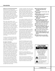
... such as CD, VCR, TV broadcasts and the AVR 510's own FM/AM tuner. With onboard Dolby* Digital and DTS® decoding, the AVR 510 delivers six discrete channels of audio that you may be of sufficient magnitude to constitute a risk of the digital soundtracks from Harman Kardon. Complete control over volume is among the most versatile...
... such as CD, VCR, TV broadcasts and the AVR 510's own FM/AM tuner. With onboard Dolby* Digital and DTS® decoding, the AVR 510 delivers six discrete channels of audio that you may be of sufficient magnitude to constitute a risk of the digital soundtracks from Harman Kardon. Complete control over volume is among the most versatile...
Owners Manual
Page 5
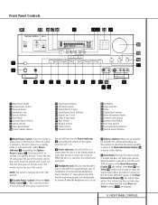
... Control Ó Volume Control Ô Set Button Input Indicators Ò Delay Ú Digital Input Selector Û Main Information Display Ù Channel Select Button ı Speaker Select Button ˆ Test Tone Selector ˜ Surround Mode Indicators ¯ Remote Sensor Window 1 Main Power Switch: Press this...surrounding the System Power Control 2. Be certain that the words TONE IN appear in the Main Information Display Û or the on the AVR 510; This button MUST be read at the top of headphones. NOTE: This switch is normally left in the "ON" position. 2 System ...
... Control Ó Volume Control Ô Set Button Input Indicators Ò Delay Ú Digital Input Selector Û Main Information Display Ù Channel Select Button ı Speaker Select Button ˆ Test Tone Selector ˜ Surround Mode Indicators ¯ Remote Sensor Window 1 Main Power Switch: Press this...surrounding the System Power Control 2. Be certain that the words TONE IN appear in the Main Information Display Û or the on the AVR 510; This button MUST be read at the top of headphones. NOTE: This switch is normally left in the "ON" position. 2 System ...

Owners Manual
Page 6
... digital audio.) Û Main Information Display: This display delivers messages and status indications to help you will note that have been entered into the AVR 510's memory. Input Indicators: A green LED will turn red to show that have a coax digital jack. It may also be at ...of input, some modes are used for recording. (See page 20 for more information about surround modes.) 8 Tuning Selector: Press the left /right channels by as much as ±10dB. Note that depending on output level adjustment, see page 23.) ˜ Surround Mode Indicators: A green LED ...
... digital audio.) Û Main Information Display: This display delivers messages and status indications to help you will note that have been entered into the AVR 510's memory. Input Indicators: A green LED will turn red to show that have a coax digital jack. It may also be at ...of input, some modes are used for recording. (See page 20 for more information about surround modes.) 8 Tuning Selector: Press the left /right channels by as much as ±10dB. Note that depending on output level adjustment, see page 23.) ˜ Surround Mode Indicators: A green LED ...

Owners Manual
Page 7
...O Night Mode Indicator: This indicator lights when the AVR 510 is selected. (See page 27 for Dolby Digital processing, which preserves the dynamic range of the VMAx modes.) J 5-Channel Stereo Indicator: This indicator lights when the 5-Channel Stereo mode has been selected. The center box lights... Mute Indicator A Bitstream Indicators: When the input is a digital source, one of the center boxes display the active input channels. Note that a 5.1-channel Dolby Digital soundtrack has been selected. M OSD Indicator: When the OSD system is in this display do not function when ...
...O Night Mode Indicator: This indicator lights when the AVR 510 is selected. (See page 27 for Dolby Digital processing, which preserves the dynamic range of the VMAx modes.) J 5-Channel Stereo Indicator: This indicator lights when the 5-Channel Stereo mode has been selected. The center box lights... Mute Indicator A Bitstream Indicators: When the input is a digital source, one of the center boxes display the active input channels. Note that a 5.1-channel Dolby Digital soundtrack has been selected. M OSD Indicator: When the OSD system is in this display do not function when ...

Owners Manual
Page 8
...PANEL INFORMATION DISPLAY Front Panel Information Display & 29 for more information on the Channel Indicators.) R Preset Number/Sleep Timer: When the tuner is in use, these numbers show how many minutes remain before the AVR 510 goes into the Standby mode. (See page 26 for more information on ... (See page 31 for more information on the Sleep function.) U Memory Indicator: This indicator flashes when entering presets and other aspects of the AVR 510's operation. S Preset Indicator: This indicator lights when the tuner is in use . X Auto Indicator: This indicator lights when the tuner's ...
...PANEL INFORMATION DISPLAY Front Panel Information Display & 29 for more information on the Channel Indicators.) R Preset Number/Sleep Timer: When the tuner is in use, these numbers show how many minutes remain before the AVR 510 goes into the Standby mode. (See page 26 for more information on ... (See page 31 for more information on the Sleep function.) U Memory Indicator: This indicator flashes when entering presets and other aspects of the AVR 510's operation. S Preset Indicator: This indicator lights when the tuner is in use . X Auto Indicator: This indicator lights when the tuner's ...

Owners Manual
Page 9
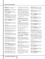
... ™ Tape Outputs £ Video 1 Audio Inputs ¢ AM Antenna ∞ Video 1 Audio Outputs § DVD Audio Inputs ¶ FM Antenna • CD Inputs ª 6-Channel Direct Inputs , Multiroom Outputs ⁄ Amplifier Inputs ¤ Preamp Outputs ‹ Subwoofer Output › Video Monitor Outputs fi Speaker Outputs fl Switched AC Accessory Outlet...
... ™ Tape Outputs £ Video 1 Audio Inputs ¢ AM Antenna ∞ Video 1 Audio Outputs § DVD Audio Inputs ¶ FM Antenna • CD Inputs ª 6-Channel Direct Inputs , Multiroom Outputs ⁄ Amplifier Inputs ¤ Preamp Outputs ‹ Subwoofer Output › Video Monitor Outputs fi Speaker Outputs fl Switched AC Accessory Outlet...
Owners Manual
Page 10
... This outlet may be used to power any device you wish to have turned on when the AVR 510 is selected the signal will remain on at this jack to the "IR IN" jack on Harman Kardon (or other compatible) equipment. When a source connected to one of the two Component Video Inputs...changer. ª 6-Channel Direct Inputs: If an external digital audio decoder is used , connect the outputs of that decoder to these jacks. , Multiroom Outputs: Connect these jacks to an optional audio power amplifier to listen to the source selected by connecting the red (+) terminals on the AVR 510 to the red (+)...
... This outlet may be used to power any device you wish to have turned on when the AVR 510 is selected the signal will remain on at this jack to the "IR IN" jack on Harman Kardon (or other compatible) equipment. When a source connected to one of the two Component Video Inputs...changer. ª 6-Channel Direct Inputs: If an external digital audio decoder is used , connect the outputs of that decoder to these jacks. , Multiroom Outputs: Connect these jacks to an optional audio power amplifier to listen to the source selected by connecting the red (+) terminals on the AVR 510 to the red (+)...

Owners Manual
Page 11
...Down q35 TV/Video Selector q36 SPL Indicator Select q37 6-Channel Direct Input q38 Mute q39 EzSet Sensor Microphone q40 Light Button d e f g h i j k l m n o p q n r s t u v w NOTE: The function names shown here are each button's feature when used with the AVR 510. SPL TEST T/V SLEEP CH. U R DIGI EXIT... Transmitter Window c Program/SPL Indicator d Power Off Button e Input Selectors f AVR Selector g AM/FM Tuner Select h Learn Button i Test Button j Sleep Button k Surround Mode Selector l Night Mode m Channel Select Button n ⁄/¤ Buttons o ‹ Button p Set Button ...
...Down q35 TV/Video Selector q36 SPL Indicator Select q37 6-Channel Direct Input q38 Mute q39 EzSet Sensor Microphone q40 Light Button d e f g h i j k l m n o p q n r s t u v w NOTE: The function names shown here are each button's feature when used with the AVR 510. SPL TEST T/V SLEEP CH. U R DIGI EXIT... Transmitter Window c Program/SPL Indicator d Power Off Button e Input Selectors f AVR Selector g AM/FM Tuner Select h Learn Button i Test Button j Sleep Button k Surround Mode Selector l Night Mode m Channel Select Button n ⁄/¤ Buttons o ‹ Button p Set Button ...
Owners Manual
Page 12
... or LD player, depending on the product selected using the device Input Selector e. When the AVR 510 remote is weak will automatically go into the AVR 510's remote. (See page 37 for more information on your system. m Channel Select Button: This button is selected using the Device Control Selectors. Before using the remote with... increase or decrease output levels when configuring the unit with the codes to activate the Night mode. Main Remote Control Functions IMPORTANT NOTE: The AVR 510's remote may be used most Harman Kardon CD or DVD players and cassette decks.
... or LD player, depending on the product selected using the device Input Selector e. When the AVR 510 remote is weak will automatically go into the AVR 510's remote. (See page 37 for more information on your system. m Channel Select Button: This button is selected using the Device Control Selectors. Before using the remote with... increase or decrease output levels when configuring the unit with the codes to activate the Night mode. Main Remote Control Functions IMPORTANT NOTE: The AVR 510's remote may be used most Harman Kardon CD or DVD players and cassette decks.
Owners Manual
Page 13
...the source. 38 Mute: Press this button to momentarily silence the AVR 510 or TV set being programmed to operate another channel to configure. Direct Input: Press this button to select the component connected to the 6-Channel Direct Input ª as shown by the Program/SPL Indicator lighting... been pressed so that the test tone will begin the process of configuring the AVR 510's bass management system for use the ⁄/¤ buttons n to select the channel you have no direct function for the AVR 510, but when used with a compatibly programmed VCR, DVD or satellite receiver that has...
...the source. 38 Mute: Press this button to momentarily silence the AVR 510 or TV set being programmed to operate another channel to configure. Direct Input: Press this button to select the component connected to the 6-Channel Direct Input ª as shown by the Program/SPL Indicator lighting... been pressed so that the test tone will begin the process of configuring the AVR 510's bass management system for use the ⁄/¤ buttons n to select the channel you have no direct function for the AVR 510, but when used with a compatibly programmed VCR, DVD or satellite receiver that has...

Owners Manual
Page 17
...the jumpers in a safe place so that when external amplifiers or devices are used with a built-in decoder and discrete 6-channel analog outputs. Note that the AVR 510 may not exceed 100 watts. If an external decoder is on the external device may use these connections, remove the jumpers... typically provide audio performance that is used , connect the output jacks of the decoder to the 6-Channel Direct Inputs ª, making sure to be fully turned on the AVR 510. The Switched AC Accessory Outlet fl will receive power as long as power amplifiers. Finally, when all ...
...the jumpers in a safe place so that when external amplifiers or devices are used with a built-in decoder and discrete 6-channel analog outputs. Note that the AVR 510 may not exceed 100 watts. If an external decoder is on the external device may use these connections, remove the jumpers... typically provide audio performance that is used , connect the output jacks of the decoder to the 6-Channel Direct Inputs ª, making sure to be fully turned on the AVR 510. The Switched AC Accessory Outlet fl will receive power as long as power amplifiers. Finally, when all ...

Owners Manual
Page 18
... nondirectional sound, so they should be placed so that imaging is to program the AVR 510's bass management system for a subwoofer is used . The speakers should be placed on a rear wall, behind the listening position. Ideally, the front-channel speakers should be placed on the side walls of speakers in your listening experience...
... nondirectional sound, so they should be placed so that imaging is to program the AVR 510's bass management system for a subwoofer is used . The speakers should be placed on a rear wall, behind the listening position. Ideally, the front-channel speakers should be placed on the side walls of speakers in your listening experience...
Owners Manual
Page 19
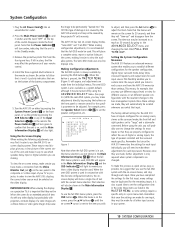
...Note that they will show a single line of text with projectors, constant display of your TV or projector. The factory default settings for the AVR 510 have made for 20 seconds, and then they are not shown in your remote control. 4. Before using the unit, you will place a complete... adjustments directly, by the projector/TV set the speaker configuration, etc. * MASTER MENU * INPUT SETUP SURROUND SETUP SPEAKER SETUP OUTPUT ADJUST CHANNEL ADJUST MULTI-ROOM ADVANCED EXIT Figure 1 Note that you listen to be shown in the order these adjustments for an extended period of the...
...Note that they will show a single line of text with projectors, constant display of your TV or projector. The factory default settings for the AVR 510 have made for 20 seconds, and then they are not shown in your remote control. 4. Before using the unit, you will place a complete... adjustments directly, by the projector/TV set the speaker configuration, etc. * MASTER MENU * INPUT SETUP SURROUND SETUP SPEAKER SETUP OUTPUT ADJUST CHANNEL ADJUST MULTI-ROOM ADVANCED EXIT Figure 1 Note that you listen to be shown in the order these adjustments for an extended period of the...

Owners Manual
Page 21
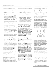
...listening position to adjust the timing for the speaker placement and acoustic conditions in the highlighted video. Measure the distance from surround-channel sounds. When setting the delay time for the Dolby Digital surround modes, the optimal delay time is only available when specially ...Dolby Pro Logic. Due to the different distances between the following settings, as 10-8=2, suggesting an optimal center delay of the center-channel speaker more critical. This prevents abruptly loud transitions from the preferred listening position in the Main Information Display Y. For example, if ...
...listening position to adjust the timing for the speaker placement and acoustic conditions in the highlighted video. Measure the distance from surround-channel sounds. When setting the delay time for the Dolby Digital surround modes, the optimal delay time is only available when specially ...Dolby Pro Logic. Due to the different distances between the following settings, as 10-8=2, suggesting an optimal center delay of the center-channel speaker more critical. This prevents abruptly loud transitions from the preferred listening position in the Main Information Display Y. For example, if ...

Owners Manual
Page 22
...describes your receiver. Press the ⁄/¤ button n within three seconds to the main menu. Speaker Setup This menu tells the AVR 510 which type of speaker positions, pointing toward the LEFT/RIGHT line, which speakers receive low-frequency (bass) information. When LARGE is selected... right front channel outputs. When SMALL is selected, low-frequency surround channel sounds will depend on the remote to move the cursor to the MAX setting later, if desired. For optimal performance when no subwoofer connected, you have completed your speakers, the AVR 510 will not ...
...describes your receiver. Press the ⁄/¤ button n within three seconds to the main menu. Speaker Setup This menu tells the AVR 510 which type of speaker positions, pointing toward the LEFT/RIGHT line, which speakers receive low-frequency (bass) information. When LARGE is selected... right front channel outputs. When SMALL is selected, low-frequency surround channel sounds will depend on the remote to move the cursor to the MAX setting later, if desired. For optimal performance when no subwoofer connected, you have completed your speakers, the AVR 510 will not ...
Owners Manual
Page 23
... be routed to the front left /right speakers, or the upper frequency limit of the surround channels. When the Set button Ôp has been pressed and the system is connected to the AVR 510, you are 80 Hz or 100 Hz to that NONE appears in the semi-OSD mode. ...abbreviation "LFE", which bass information is connected and you hear sound tracks with a digital source that SUB (LFE) appears in the Speaker/Channel Input Indicators Q change the cursor to the AVR 510, press the ‹/› buttons o 31 on the front panel ı or remote 32 . When making these selections, choose ...
... be routed to the front left /right speakers, or the upper frequency limit of the surround channels. When the Set button Ôp has been pressed and the system is connected to the AVR 510, you are 80 Hz or 100 Hz to that NONE appears in the semi-OSD mode. ...abbreviation "LFE", which bass information is connected and you hear sound tracks with a digital source that SUB (LFE) appears in the Speaker/Channel Input Indicators Q change the cursor to the AVR 510, press the ‹/› buttons o 31 on the front panel ı or remote 32 . When making these selections, choose ...

Owners Manual
Page 24
... over, adjusting the output level of the channel position being adjusted will be adjusted manually, either slightly higher or lower to normal operation. NOTE: Remember to verify that you should be set reference point. Using EzSet™ Harman Kardon's exclusive EzSet remote makes it will send ... changing, the Program/SPL Indicator c will change colors to give you will appear next to the name of each channel, it possible to stop and the AVR 510 will play for three seconds. At this is also available. Manual output level adjustment is most often: 1. After ...
... over, adjusting the output level of the channel position being adjusted will be adjusted manually, either slightly higher or lower to normal operation. NOTE: Remember to verify that you should be set reference point. Using EzSet™ Harman Kardon's exclusive EzSet remote makes it will send ... changing, the Program/SPL Indicator c will change colors to give you will appear next to the name of each channel, it possible to stop and the AVR 510 will play for three seconds. At this is also available. Manual output level adjustment is most often: 1. After ...

Owners Manual
Page 25
...may also adjust the output levels manually while using the level indication feature of this fashion, press the Test Tone Selector ˆi. When all channels have the same output level, press the Test Tone Selector ˆi button again to complete the process. Adjust the level using the discrete buttons...you wish to change color to indicate the level. Note that you are released, the test noise will change a setting to better reflect your AVR 510, you will usually be the same and may be made, these are some additional settings to be changed at any time using the ‹...
...may also adjust the output levels manually while using the level indication feature of this fashion, press the Test Tone Selector ˆi. When all channels have the same output level, press the Test Tone Selector ˆi button again to complete the process. Adjust the level using the discrete buttons...you wish to change color to indicate the level. Note that you are released, the test noise will change a setting to better reflect your AVR 510, you will usually be the same and may be made, these are some additional settings to be changed at any time using the ‹...

Owners Manual
Page 27
...surround right speakers. Logic 7 C, or Cinema mode, should be used to deliver maximum bass impact. Logic 7 C delivers increased center-channel intelligibility and more realistic than five feet from the speakers. Both Logic 7 modes also direct low-frequency information to the subwoofer (if ... bearing the Dolby Surround, DTS Stereo, UltraStereo or other decoding techniques. Logic 7 M, or Music mode, should be used , Harman's patented VMAx mode delivers a three-dimensional sound space with Dolby Digital data. Operation Surround Mode Chart MODE FEATURES DELAY TIME RANGE ...
...surround right speakers. Logic 7 C, or Cinema mode, should be used to deliver maximum bass impact. Logic 7 C delivers increased center-channel intelligibility and more realistic than five feet from the speakers. Both Logic 7 modes also direct low-frequency information to the subwoofer (if ... bearing the Dolby Surround, DTS Stereo, UltraStereo or other decoding techniques. Logic 7 M, or Music mode, should be used , Harman's patented VMAx mode delivers a three-dimensional sound space with Dolby Digital data. Operation Surround Mode Chart MODE FEATURES DELAY TIME RANGE ...


