

Owners Manual
Page 3
.... INTRODUCTION 3 While complex digital systems are available, and a total of six digital inputs make all the latest digital audio sources. To obtain the maximum enjoyment from the latest DVD releases and Digital Television broadcasts. This will enable you to Portable Digital ... to digital recorders. They are about this equipment not expressly approved by Harman Kardon. Coax and optical digital audio outputs are available. With state-of-the-art circuitry and timehonored circuit designs, the AVR 130 is easy to configure so that may cause interference to begin many years...
.... INTRODUCTION 3 While complex digital systems are available, and a total of six digital inputs make all the latest digital audio sources. To obtain the maximum enjoyment from the latest DVD releases and Digital Television broadcasts. This will enable you to Portable Digital ... to digital recorders. They are about this equipment not expressly approved by Harman Kardon. Coax and optical digital audio outputs are available. With state-of-the-art circuitry and timehonored circuit designs, the AVR 130 is easy to configure so that may cause interference to begin many years...

Owners Manual
Page 5
... no matter how the actual Bass and Treble Controls ÓÚ are adjusted. 6 Speaker Selector: Press this button to the AVR 130. When the unit is on speaker setup and configuration.) 7 Surround Mode Group Selector: Press this illustration, a larger copy may... 3 FMAM TAPE 6 CH Surr. Tuner Band Selector @ Set Button # Digital Input Selector $ Preset Stations Selector % Delay Adjust Selector ^ Input Source Selector & Tuner Mode Selector * Optical 3 Digital Input ( Coaxial 3 Digital Input Ó Bass Control Ô Video 3 Video Input Jacks Video 3 Audio Input Jacks &#...
... no matter how the actual Bass and Treble Controls ÓÚ are adjusted. 6 Speaker Selector: Press this button to the AVR 130. When the unit is on speaker setup and configuration.) 7 Surround Mode Group Selector: Press this illustration, a larger copy may... 3 FMAM TAPE 6 CH Surr. Tuner Band Selector @ Set Button # Digital Input Selector $ Preset Stations Selector % Delay Adjust Selector ^ Input Source Selector & Tuner Mode Selector * Optical 3 Digital Input ( Coaxial 3 Digital Input Ó Bass Control Ô Video 3 Video Input Jacks Video 3 Audio Input Jacks &#...

Owners Manual
Page 6
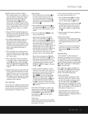
...encountered, press the button so that have been entered into the AVR 130's memory. # Digital Input Selector: Press this button to select one increment. When weak reception is in the Lower Display Line ¯. For a digital source, the indicators will read AUTO ST TUNED. When the letters ...% Delay Adjust Selector: Press this button to begin the process of trimming the channel output levels using the tuner.) * Optical 3 Digital Input: Connect the optical digital audio output of messages will indicate AUTO TUNED. Aim the remote at the digital input. The specific modes will vary ...
...encountered, press the button so that have been entered into the AVR 130's memory. # Digital Input Selector: Press this button to select one increment. When weak reception is in the Lower Display Line ¯. For a digital source, the indicators will read AUTO ST TUNED. When the letters ...% Delay Adjust Selector: Press this button to begin the process of trimming the channel output levels using the tuner.) * Optical 3 Digital Input: Connect the optical digital audio output of messages will indicate AUTO TUNED. Aim the remote at the digital input. The specific modes will vary ...
Owners Manual
Page 8
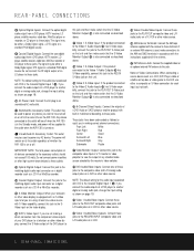
...turned on a VCR. NOTE: The default setting for the audio input associated with the antenna. REAR-PANEL CONNECTIONS • Optical Digital Inputs: Connect the optical digital audio output from a DVD player, HDTV receiver, LD player, satellite receiver, cable box, MiniDisc player or recorder, .... ¤ Unswitched AC Accessory Outlet: This outlet may be supplied to the outlet when the AVR 130 is the Coaxial Digital Input 1 ª. Note on a VCR or other video source. Any device connected to the PLAY/OUT composite video jacks and L/R audio jacks on Video Connections:...
...turned on a VCR. NOTE: The default setting for the audio input associated with the antenna. REAR-PANEL CONNECTIONS • Optical Digital Inputs: Connect the optical digital audio output from a DVD player, HDTV receiver, LD player, satellite receiver, cable box, MiniDisc player or recorder, .... ¤ Unswitched AC Accessory Outlet: This outlet may be supplied to the outlet when the AVR 130 is the Coaxial Digital Input 1 ª. Note on a VCR or other video source. Any device connected to the PLAY/OUT composite video jacks and L/R audio jacks on Video Connections:...
Owners Manual
Page 13
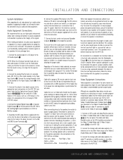
... speaker manufacturers adhere to the Video 2 Audio/Video and S-Video Jacks ·f. 3. Connect the Optical Digital Output ‹ or Coaxial Digital Output › on the rear panel of the AVR 130 to preserve the integrity of cable selected, we recommend that you do not know the polarity of ...on the VCR should have color-coded connections, match the terminal on the AVR 130 to the Video 3 Jacks Ô on the AVR 130. 3. Assemble the AM Loop Antenna supplied with UL, CSA or other video source, to the like terminal on your speakers have the appropriate markings to ...
... speaker manufacturers adhere to the Video 2 Audio/Video and S-Video Jacks ·f. 3. Connect the Optical Digital Output ‹ or Coaxial Digital Output › on the rear panel of the AVR 130 to preserve the integrity of cable selected, we recommend that you do not know the polarity of ...on the VCR should have color-coded connections, match the terminal on the AVR 130 to the Video 3 Jacks Ô on the AVR 130. 3. Assemble the AM Loop Antenna supplied with UL, CSA or other video source, to the like terminal on your speakers have the appropriate markings to ...
Owners Manual
Page 14
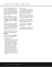
... player, the default connection is connected to a TV set or video display with S-Video capability. You're almost ready to the appropriate Optical or Coaxial Digital Inputs •ª*(. 6. Connect the composite video output of your system, it is necessary to power accessory devices, but... draw to the DVD Audio Inputs c. If you connect both ends) between the AVR 130 and your television monitor or video projector. Finally, when all connections are used to make that the digital input source selection is recommended for the audio. 5. Connect the left in their native formats....
... player, the default connection is connected to a TV set or video display with S-Video capability. You're almost ready to the appropriate Optical or Coaxial Digital Inputs •ª*(. 6. Connect the composite video output of your system, it is necessary to power accessory devices, but... draw to the DVD Audio Inputs c. If you connect both ends) between the AVR 130 and your television monitor or video projector. Finally, when all connections are used to make that the digital input source selection is recommended for the audio. 5. Connect the left in their native formats....
Owners Manual
Page 23
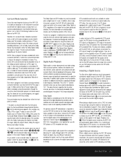
...any of the OPTICAL or COAXIAL inputs, as they appear in all , a total of 16 listening modes are available on page 21. Selecting a Digital Source To utilize either the Optical or Coaxial input on personal taste, as well as the program is a standard part of the AVR 130. In order... to provide a backup signal and a source for analog stereo recording, the analog outputs provided on digital...
...any of the OPTICAL or COAXIAL inputs, as they appear in all , a total of 16 listening modes are available on page 21. Selecting a Digital Source To utilize either the Optical or Coaxial input on personal taste, as well as the program is a standard part of the AVR 130. In order... to provide a backup signal and a source for analog stereo recording, the analog outputs provided on digital...
Owners Manual
Page 25
... digital audio tracks on the front panel or remote. When the tuner receives a strong enough signal for listening through the AVR 130 is connected to the Optical ‹ or Coaxial › Digital Audio Outputs, you wish to start over. To enter a station's frequency directly,...™ and Video 1 Audio Outputs e. Tape Recording In normal operation, the audio or video source selected for adequate reception, MANUAL TUNED will be compatible with either the AVR 130 or the source machine. This is selected. 3. Station Selection 1. again to the location where you may be ...
... digital audio tracks on the front panel or remote. When the tuner receives a strong enough signal for listening through the AVR 130 is connected to the Optical ‹ or Coaxial › Digital Audio Outputs, you wish to start over. To enter a station's frequency directly,...™ and Video 1 Audio Outputs e. Tape Recording In normal operation, the audio or video source selected for adequate reception, MANUAL TUNED will be compatible with either the AVR 130 or the source machine. This is selected. 3. Station Selection 1. again to the location where you may be ...

Product Information
Page 17
...1005 AVR 7300 AVR 630 AVR 430 A/V Inputs 6 6 6 5 5 S-Video Inputs 6 6 6 5 5 Analog Audio Inputs 4 4 4 4 4 Digital Audio Inputs (Coax/Optical) Rear panel 2/2 Front panel 1/1 Rear panel 2/2 Front panel 1/1 Rear panel 3/3 Front panel 1/1 Rear panel 2/2 Front panel 1/1 Rear panel 2/2 Front panel 1/1 Digital Audio Outputs (Coax/Optical) ...-bit 2 No No EzSet, 8-device programmable Yes Yes No Color-coded binding posts 6-5/8" x 17-5/16" x 15" 28 lb AVR 130 4 4 4 Rear panel 2/2 Front panel 1/1 Rear panel 1/1 No 6-Channel Subwoofer No Triple crossover No Cirrus® CS 49300 ...
...1005 AVR 7300 AVR 630 AVR 430 A/V Inputs 6 6 6 5 5 S-Video Inputs 6 6 6 5 5 Analog Audio Inputs 4 4 4 4 4 Digital Audio Inputs (Coax/Optical) Rear panel 2/2 Front panel 1/1 Rear panel 2/2 Front panel 1/1 Rear panel 3/3 Front panel 1/1 Rear panel 2/2 Front panel 1/1 Rear panel 2/2 Front panel 1/1 Digital Audio Outputs (Coax/Optical) ...-bit 2 No No EzSet, 8-device programmable Yes Yes No Color-coded binding posts 6-5/8" x 17-5/16" x 15" 28 lb AVR 130 4 4 4 Rear panel 2/2 Front panel 1/1 Rear panel 1/1 No 6-Channel Subwoofer No Triple crossover No Cirrus® CS 49300 ...

Quick Start Guide
Page 1
...Harman Kardon AVR 130. SPEAKER PLACEMENT Place your source equipment or speakers. The colors are standardized, but not all equipment or connectors use them. This Quick-Start Guide will help you with a basic system installation. Connections Color Guide Audio Connections Left Right Front Center Surround Subwoofer Digital Audio Connections Coax Optical... Video Connections Composite S-Video Match the colored jacks on the AVR 130 to the pages referenced in the listening room (see page...
...Harman Kardon AVR 130. SPEAKER PLACEMENT Place your source equipment or speakers. The colors are standardized, but not all equipment or connectors use them. This Quick-Start Guide will help you with a basic system installation. Connections Color Guide Audio Connections Left Right Front Center Surround Subwoofer Digital Audio Connections Coax Optical... Video Connections Composite S-Video Match the colored jacks on the AVR 130 to the pages referenced in the listening room (see page...

Quick Start Guide
Page 3
... Step 8. Set output levels: Set the Balance to 12 o'clock, and the Volume to select an optical or coax digital input (see pages 19 and 23). If you become familiar with the AVR 130; Press the Test button again. (See pages 18-19.) Step 11. SPEAKER AND AUDIO CONNECTIONS The Coax...to coax (orange) OR optical to match the type of the AVR 130 should be reassigned. Connect the composite and S-Video Monitor outputs to your DVD is connected to Coax 1, no adjustment is needed if you have an SPL meter, set 's input to optical for the currently selected source. Configure speakers: No ...
... Step 8. Set output levels: Set the Balance to 12 o'clock, and the Volume to select an optical or coax digital input (see pages 19 and 23). If you become familiar with the AVR 130; Press the Test button again. (See pages 18-19.) Step 11. SPEAKER AND AUDIO CONNECTIONS The Coax...to coax (orange) OR optical to match the type of the AVR 130 should be reassigned. Connect the composite and S-Video Monitor outputs to your DVD is connected to Coax 1, no adjustment is needed if you have an SPL meter, set 's input to optical for the currently selected source. Configure speakers: No ...

Quick Start Guide
Page 4
... York 11797 www.harmankardon.com © 2003 Harman International Industries, Incorporated Part No. When both composite and S-Video sources are connected to the AVR you may use either type (but not both ) for each digital audio source. Device Connection Options: Recommended connections are on ...cable company to your system requirements. Dotted lines indicate composite or S-Video connections. Video Connections Dashed lines (- - - -) indicate coax and optical digital audio connections. CQE1A198Z In/Rec VCR (Video 1) L R VIDEO Out/Play TV or Video Monitor Video S-Video IN Cable or ...
... York 11797 www.harmankardon.com © 2003 Harman International Industries, Incorporated Part No. When both composite and S-Video sources are connected to the AVR you may use either type (but not both ) for each digital audio source. Device Connection Options: Recommended connections are on ...cable company to your system requirements. Dotted lines indicate composite or S-Video connections. Video Connections Dashed lines (- - - -) indicate coax and optical digital audio connections. CQE1A198Z In/Rec VCR (Video 1) L R VIDEO Out/Play TV or Video Monitor Video S-Video IN Cable or ...


