
Owners Manual
Page 1
The Harman/Kardon Model 75+ AM/Stereo FM Multichannel Receiver harman/kardon THE MUSIC COMPANY Instruction Manual
The Harman/Kardon Model 75+ AM/Stereo FM Multichannel Receiver harman/kardon THE MUSIC COMPANY Instruction Manual
Owners Manual
Page 2
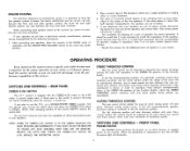
... our satisfaction to be installed as , in concept and design. INTRODUCTION You are certain aspects of the room involving you completely with spacious, three dimensional sound. In the event your unit. The Harman/Kardon Model 75 + multichannel receiver encompasses the best of all of the required conveniences so essential for four channel reproduction. The walls of purchase. The Model 75+ is returned to...
... our satisfaction to be installed as , in concept and design. INTRODUCTION You are certain aspects of the room involving you completely with spacious, three dimensional sound. In the event your unit. The Harman/Kardon Model 75 + multichannel receiver encompasses the best of all of the required conveniences so essential for four channel reproduction. The walls of purchase. The Model 75+ is returned to...
Owners Manual
Page 3
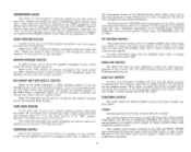
... in the rear, between 105 and 125 volts. WORK CAREFULLY TRIMMING ALL LOOSE WIRES ON THE REAR OF THE SPEAKERS AND RECEIVER. SPEAKER IMPEDANCE Each speaker system connected to your 75 + must possess an impedance of from the listener. Sufficient care should be dressed easily around the molding and it . Harman/Kardon HK50) serve well as selected by the POWER switch on the rear panel. Ordinary lamp...
... in the rear, between 105 and 125 volts. WORK CAREFULLY TRIMMING ALL LOOSE WIRES ON THE REAR OF THE SPEAKERS AND RECEIVER. SPEAKER IMPEDANCE Each speaker system connected to your 75 + must possess an impedance of from the listener. Sufficient care should be dressed easily around the molding and it . Harman/Kardon HK50) serve well as selected by the POWER switch on the rear panel. Ordinary lamp...
Owners Manual
Page 5
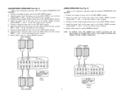
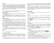
... end of your receiver. 5. on the rear panel of the lamp cord to the MAIN, FRONT screw terminals marked LEFT + and - NOTE: BE CERTAIN THAT THE STEREO/4-CH SWITCH LOCATED ON THE REAR PANEL OF THE RECEIVER IS SET IN THE STEREO POSITION FOR DOUBLE POWER STEREO OPERATION. AVOID SHORTS 4-CH FIG- 2 LEFT RIGHT BACK SPEAKERS SPEAKERS 4 - 8 -16 OHMS MAIN j / \ , REMOTE LEFT RIGHT + - - + O r O O 1Th 1- 1 0 0 1- • \ \ O CAUTION CONNECT SPEAKERS WITH CARE.
... end of your receiver. 5. on the rear panel of the lamp cord to the MAIN, FRONT screw terminals marked LEFT + and - NOTE: BE CERTAIN THAT THE STEREO/4-CH SWITCH LOCATED ON THE REAR PANEL OF THE RECEIVER IS SET IN THE STEREO POSITION FOR DOUBLE POWER STEREO OPERATION. AVOID SHORTS 4-CH FIG- 2 LEFT RIGHT BACK SPEAKERS SPEAKERS 4 - 8 -16 OHMS MAIN j / \ , REMOTE LEFT RIGHT + - - + O r O O 1Th 1- 1 0 0 1- • \ \ O CAUTION CONNECT SPEAKERS WITH CARE.
Owners Manual
Page 6
... 16 ohms without special transformers. The phase relationship must be adjusted to the point where you determine that it is shipped with poor transmission quality. Repeat this receiver. FRONT PANEL POWER SWITCH The POWER switch performs the function as a DOUBLE-POWER STEREO receiver, first turn the set ON the power light will also eliminate stations with the STEREO/4-CH switch in impedance from only one of phase. 4. REAR PANEL STEREO/4-CH SWITCH The 75 + receiver...
... 16 ohms without special transformers. The phase relationship must be adjusted to the point where you determine that it is shipped with poor transmission quality. Repeat this receiver. FRONT PANEL POWER SWITCH The POWER switch performs the function as a DOUBLE-POWER STEREO receiver, first turn the set ON the power light will also eliminate stations with the STEREO/4-CH switch in impedance from only one of phase. 4. REAR PANEL STEREO/4-CH SWITCH The 75 + receiver...
Owners Manual
Page 7
... the program sound level is reduced. The Harman/Kardon CONTOUR switch compensates for this switch must be depressed. For warm, full-bodied reproduction at low listening levels, throw the CONTOUR switch to play music programs at your discretion. PHONO Use these positions for full enjoyment of stereo or 4-CH high level inputs. Any standard stereo record player can be turned off at high listening levels in the "ON" position all speakers connected to station...
... the program sound level is reduced. The Harman/Kardon CONTOUR switch compensates for this switch must be depressed. For warm, full-bodied reproduction at low listening levels, throw the CONTOUR switch to play music programs at your discretion. PHONO Use these positions for full enjoyment of stereo or 4-CH high level inputs. Any standard stereo record player can be turned off at high listening levels in the "ON" position all speakers connected to station...
Owners Manual
Page 8
... an external monophonic source (one channel) is used sparingly and with RCA Decoder"). For further details refer to paragraph on the rear panel of operation. DISCRETE FM/AUX In this position the stereo indicator light and automatic switching circuit built ino your phonograph and Harman/Kardon 75 + receiver. Harman/Kardon intends to manufacture a decoder for the various sources available. AM This selects the AM section of operation. The Treble control adjusts the higher frequencies...
... an external monophonic source (one channel) is used sparingly and with RCA Decoder"). For further details refer to paragraph on the rear panel of operation. DISCRETE FM/AUX In this position the stereo indicator light and automatic switching circuit built ino your phonograph and Harman/Kardon 75 + receiver. Harman/Kardon intends to manufacture a decoder for the various sources available. AM This selects the AM section of operation. The Treble control adjusts the higher frequencies...
Owners Manual
Page 9
... used to 4-CH operation. INTEGRATED AMPLIFIERS SPEAKERS VOLUME CONTROL THE VOLUME control adjusts the signal level of faithfulness and spatial distribution. Sufficient range is almost as exciting as compared to balance all channels. TWO CHANNEL RECORDING RECOVERY CIRCUITS FOR "BACK" SOUNDS LEFT & RIGHT FRONT SPEAKER BALANCING LF (BACK SPEAKERS OFF) RF 4-CH DISCRETE In order to utilize this control to permit rebalancing of any stereo source, if your receiver...
... used to 4-CH operation. INTEGRATED AMPLIFIERS SPEAKERS VOLUME CONTROL THE VOLUME control adjusts the signal level of faithfulness and spatial distribution. Sufficient range is almost as exciting as compared to balance all channels. TWO CHANNEL RECORDING RECOVERY CIRCUITS FOR "BACK" SOUNDS LEFT & RIGHT FRONT SPEAKER BALANCING LF (BACK SPEAKERS OFF) RF 4-CH DISCRETE In order to utilize this control to permit rebalancing of any stereo source, if your receiver...
Owners Manual
Page 10
... switch in this station through the use for optimum listening performance. Thus, to this setting. Should you receive a weak stereo signal whose quality has been degraded by the interconnection of a record player, tuner and amplifier, as compared to select the desired station when your FUNCTION switch is in the FM, STEREO FM, or AM position. STEREO INDICATOR A stereo indicator is located adjacent to modify the actual frequency...
... switch in this station through the use for optimum listening performance. Thus, to this setting. Should you receive a weak stereo signal whose quality has been degraded by the interconnection of a record player, tuner and amplifier, as compared to select the desired station when your FUNCTION switch is in the FM, STEREO FM, or AM position. STEREO INDICATOR A stereo indicator is located adjacent to modify the actual frequency...
Owners Manual
Page 11
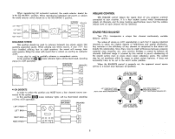
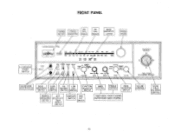
...TREBLE MODE • ...... .e VOLUME SOUND FIELD BALANCE TWIN POWER MULTICHANNEL RECE ER HEADPHONE RECEPTACLES MAIN SPEAKERS SWITCH TAPE MON-I • 2 ENHANCED • 4-CH i ; FRONT PANEL TUNING METER STEREO INDICATOR AM DIAL SCALE FM DIAL SCALE MODE INDICATOR LIGHTS TUNING KNOB ILLUMINATED POWER SWITCH harman/kardon 75-1- DOLBY NR CONTOUR T HK3H CUT SPKRS CI ) FM SIRE°. • FROND. K BASS SCI MATRIX I • MONO* I SWITCH FM LOW MUTING CUT SWITCH SWITCH FUNCTION SELECTOR SWITCH BASS CONTROL TREBLE CONTROL MODE SELECTOR SWITCH REMOTE SPEAKERS SWITCH...
...TREBLE MODE • ...... .e VOLUME SOUND FIELD BALANCE TWIN POWER MULTICHANNEL RECE ER HEADPHONE RECEPTACLES MAIN SPEAKERS SWITCH TAPE MON-I • 2 ENHANCED • 4-CH i ; FRONT PANEL TUNING METER STEREO INDICATOR AM DIAL SCALE FM DIAL SCALE MODE INDICATOR LIGHTS TUNING KNOB ILLUMINATED POWER SWITCH harman/kardon 75-1- DOLBY NR CONTOUR T HK3H CUT SPKRS CI ) FM SIRE°. • FROND. K BASS SCI MATRIX I • MONO* I SWITCH FM LOW MUTING CUT SWITCH SWITCH FUNCTION SELECTOR SWITCH BASS CONTROL TREBLE CONTROL MODE SELECTOR SWITCH REMOTE SPEAKERS SWITCH...
Owners Manual
Page 12
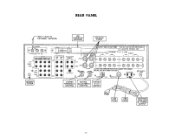
REAR PANEL 300-^- LEAD TO EXTERNAL ANTENNA AM LOOPSTICK ANTENNA SPEAKER FUSES ANTENNA FM 300^-, AM INPUTS PH0N0 DISCRETE DtSCRETE E MAG PHONO/AUX PWAUX MONA fLEFT°O O O* FRONT RIGHT 0 O O O 0 0 0 0 0 LEFT BACK 0 0 0 O RIGH0T 0 OUTPUTSTAPE TAPE OUT OUT 2 0 0 0 0 0 0 0 0 AUTION- HIGH VOLTAGE INSIDE THIS UNIT HAS NO USER SERVICEABLE BY QUAUFIED TECHICIAN ONLY r•SPEA ES I LEFT GHT SPEAKERS 41 8 - 16 OHMS MAIN REMOTE LEFT RIGHT LEFT RIGHT DOLBY/TAPE...
REAR PANEL 300-^- LEAD TO EXTERNAL ANTENNA AM LOOPSTICK ANTENNA SPEAKER FUSES ANTENNA FM 300^-, AM INPUTS PH0N0 DISCRETE DtSCRETE E MAG PHONO/AUX PWAUX MONA fLEFT°O O O* FRONT RIGHT 0 O O O 0 0 0 0 0 LEFT BACK 0 0 0 O RIGH0T 0 OUTPUTSTAPE TAPE OUT OUT 2 0 0 0 0 0 0 0 0 AUTION- HIGH VOLTAGE INSIDE THIS UNIT HAS NO USER SERVICEABLE BY QUAUFIED TECHICIAN ONLY r•SPEA ES I LEFT GHT SPEAKERS 41 8 - 16 OHMS MAIN REMOTE LEFT RIGHT LEFT RIGHT DOLBY/TAPE...
Owners Manual
Page 13
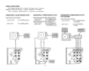
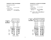
... INPUTS PHONO DISCRETE MAC PHONO/AUX LEF 0 FRONT 4.0 0 RIGHT O 0 GND LEFT 0 BACK 0 12 GROUND SCREW fl NPUT$ PHONO DISCRETE DISCRETE MAG PtIONO/AUX FWAUX ( LEFT 0O FRONT RIGHT 0 O LEFT BACK RIGHcT) GND CONNECTING A MONO RECORD PLAYER Typical Operating Conditions Function Switch: Set to PHONO position Mode Switch: Set to MONO position CONNECTING A STEREO RECORD PLAYER Typical Operating Conditions (Stereo Record) Function Switch: Mode Switch: Set to PHONO position Set to STEREO position Typical Operating Conditions (SQ Record) Function Switch: Mode Switch: Set...
... INPUTS PHONO DISCRETE MAC PHONO/AUX LEF 0 FRONT 4.0 0 RIGHT O 0 GND LEFT 0 BACK 0 12 GROUND SCREW fl NPUT$ PHONO DISCRETE DISCRETE MAG PtIONO/AUX FWAUX ( LEFT 0O FRONT RIGHT 0 O LEFT BACK RIGHcT) GND CONNECTING A MONO RECORD PLAYER Typical Operating Conditions Function Switch: Set to PHONO position Mode Switch: Set to MONO position CONNECTING A STEREO RECORD PLAYER Typical Operating Conditions (Stereo Record) Function Switch: Mode Switch: Set to PHONO position Set to STEREO position Typical Operating Conditions (SQ Record) Function Switch: Mode Switch: Set...
Owners Manual
Page 14
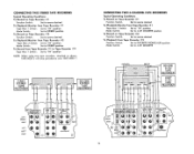
INPUTS LEFTINPDUFTSIMS,CMATRUAOIEPNTEEI-(TOOUAUTPPUTOTE2SAUPTE RIGHT FRONT LEFT RIGHT BACK O CD O LEFTINXPDFUTMSIS/CAMT7RUOAIEXPNTEEI-TOOIAUUTPPUTTOTE2SAUPTE RIGHT FRONT BRLACEIKGFHTT0O 0 13 STEREO TAPE RECORDER R LOUTPUT 0 0 V V L RNPUT A A RBALCFRKRLONT FLRROBLNARTCK 4-CH TAPE RECORDER OUTPUTS.. nected to have a 4 channel source con- CONNECTING A STEREO TAPE RECORDER Typical Operating Conditions To Record Function Switch: Set to source desired To Playback/Monitor Tape Mon 1 Switch: Mode Switch: Set to "IN" position Set to STEREO position CONNECTING A 4-CHANNEL ...
INPUTS LEFTINPDUFTSIMS,CMATRUAOIEPNTEEI-(TOOUAUTPPUTOTE2SAUPTE RIGHT FRONT LEFT RIGHT BACK O CD O LEFTINXPDFUTMSIS/CAMT7RUOAIEXPNTEEI-TOOIAUUTPPUTTOTE2SAUPTE RIGHT FRONT BRLACEIKGFHTT0O 0 13 STEREO TAPE RECORDER R LOUTPUT 0 0 V V L RNPUT A A RBALCFRKRLONT FLRROBLNARTCK 4-CH TAPE RECORDER OUTPUTS.. nected to have a 4 channel source con- CONNECTING A STEREO TAPE RECORDER Typical Operating Conditions To Record Function Switch: Set to source desired To Playback/Monitor Tape Mon 1 Switch: Mode Switch: Set to "IN" position Set to STEREO position CONNECTING A 4-CHANNEL ...
Owners Manual
Page 15
... Switch: Set to source desired To Playback/Monitor from Tape Recorder #2 Tape Mon 2 Switch: Set to "IN" position Mode Switch: Set to STEREO position To Record from Tape Recorder #2 Function Switch: Mode Switch: Set to DISCRETE PHONO/AUX position Set to "IN" position NOTE: When using two tape recorders, attached as shown, TAPE MON 2 will take precedence over TAPE MON 1 FIRST STEREO TAPE RECORDER OUTPUT RL vv INPUT LR A A INPUT R L 0 0 v v SECOND OUTPUT ""IP...
... Switch: Set to source desired To Playback/Monitor from Tape Recorder #2 Tape Mon 2 Switch: Set to "IN" position Mode Switch: Set to STEREO position To Record from Tape Recorder #2 Function Switch: Mode Switch: Set to DISCRETE PHONO/AUX position Set to "IN" position NOTE: When using two tape recorders, attached as shown, TAPE MON 2 will take precedence over TAPE MON 1 FIRST STEREO TAPE RECORDER OUTPUT RL vv INPUT LR A A INPUT R L 0 0 v v SECOND OUTPUT ""IP...
Owners Manual
Page 16
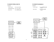
TAPE OUT I LEFT C FRONT RIGHT LEFT BACK RIGHT -OUTPUTS- TO CONNECT EXTERNAL DOLBY NR To Operate Function Switch: Set to source desired Ext Dolby NR Switch: Set to "IN" position Mode Switch: Set to STEREO position TO CONNECT FOR DISCRETE FM To Operate Function Switch: Set to DISCRETE FM/AUX position Mode Switch: Set to 4-CH DISCRETE position R L OUT L R DOLBY NOISE REDUCER DOLBY/TAPE MON 2 OUT IN LEFT RIGHT OUTPUTS :INPUT FRONT BACK L RLR VVVV DISCRETE FM DECODER...
TAPE OUT I LEFT C FRONT RIGHT LEFT BACK RIGHT -OUTPUTS- TO CONNECT EXTERNAL DOLBY NR To Operate Function Switch: Set to source desired Ext Dolby NR Switch: Set to "IN" position Mode Switch: Set to STEREO position TO CONNECT FOR DISCRETE FM To Operate Function Switch: Set to DISCRETE FM/AUX position Mode Switch: Set to 4-CH DISCRETE position R L OUT L R DOLBY NOISE REDUCER DOLBY/TAPE MON 2 OUT IN LEFT RIGHT OUTPUTS :INPUT FRONT BACK L RLR VVVV DISCRETE FM DECODER...
Owners Manual
Page 17
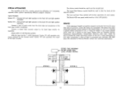
... position. Mode switch to the back tape monitor receptacles. SERVICE If this instrument to Harman/Kardon without first receiving authorization. OUT L O R FRONT BACK SPEAKERS SYSTEM I LEVEL STEREO SOURCE FRONT L R BACK RL D TAPE TAPE MON. With the tape monitor 1 switch depressed, System #1 will function separately for instructions. Please write our Customer Service Department, Harman/Kardon, Incorporated, Plainview, New York 11803. Typical Example System #1 - The Stereo-4-CH rear panel switch must be used to...
... position. Mode switch to the back tape monitor receptacles. SERVICE If this instrument to Harman/Kardon without first receiving authorization. OUT L O R FRONT BACK SPEAKERS SYSTEM I LEVEL STEREO SOURCE FRONT L R BACK RL D TAPE TAPE MON. With the tape monitor 1 switch depressed, System #1 will function separately for instructions. Please write our Customer Service Department, Harman/Kardon, Incorporated, Plainview, New York 11803. Typical Example System #1 - The Stereo-4-CH rear panel switch must be used to...
Owners Manual
Page 18
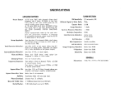
.... SPECIFICATIONS AMPLIFIER SECTION Power Output: 45/45 watts, RMS, both channels driven simultaneously into 8 ohms, 20-20kHz at less than 0.5% THD at 120 volts, 50/60 Hertz AC. (In special double power stereo mode) 4x 18 watts, RMS into 8 ohms, all channels driven in stereo or 4-CH mode. Hum and Noise: Better than 0.5% THD at any type load. Image Frequency Rejection: Better than 75 millivolts...
.... SPECIFICATIONS AMPLIFIER SECTION Power Output: 45/45 watts, RMS, both channels driven simultaneously into 8 ohms, 20-20kHz at less than 0.5% THD at 120 volts, 50/60 Hertz AC. (In special double power stereo mode) 4x 18 watts, RMS into 8 ohms, all channels driven in stereo or 4-CH mode. Hum and Noise: Better than 0.5% THD at any type load. Image Frequency Rejection: Better than 75 millivolts...


