
User Manual
Page 2
... practices not related to personal injury. Wear ANSI-approved safety goggles with side shields. Wear heavy-duty work gloves. Table of Puncture Injury. Symbol property or statement Warning marking concerning Risk of contents Safety 2 Specifications 7 Setup 9 Operation 12 Maintenance 14 Parts List and Diagram 17 Warranty 20 SAFETy SETUp OpERATION WARNING SyMBOLS AND DEFINITIONS This is used to alert you to avoid possible injury or death...
... practices not related to personal injury. Wear ANSI-approved safety goggles with side shields. Wear heavy-duty work gloves. Table of Puncture Injury. Symbol property or statement Warning marking concerning Risk of contents Safety 2 Specifications 7 Setup 9 Operation 12 Maintenance 14 Parts List and Diagram 17 Warranty 20 SAFETy SETUp OpERATION WARNING SyMBOLS AND DEFINITIONS This is used to alert you to avoid possible injury or death...

User Manual
Page 3
... medication. Avoid unintentional starting. d. f. Do not fire fastener on trigger, the tool is able to the air supply. Remove finger from moving parts. Proper footing and balance enables better control of another fastener. Do not point the tool toward yourself or anyone whether it contains fasteners or not. This is released before using the tool. OpERATION MAINTENANcE Item 69719 For technical questions, please...
... medication. Avoid unintentional starting. d. f. Do not fire fastener on trigger, the tool is able to the air supply. Remove finger from moving parts. Proper footing and balance enables better control of another fastener. Do not point the tool toward yourself or anyone whether it contains fasteners or not. This is released before using the tool. OpERATION MAINTENANcE Item 69719 For technical questions, please...
User Manual
Page 4
... able to result in a risk of injury to using . Always verify prior to persons or tool damage when used until repaired. f. SAFETy SETUp Tool use the tool if the trigger does not turn the tool on the tool. A tool is designed. When servicing a tool, use with care. b. g. Use only authorized parts. Use of injury to a stable platform. d. Use clamps or another practical way to secure and support the workpiece to persons. SAVE THESE INSTRUcTIONS.
... able to result in a risk of injury to using . Always verify prior to persons or tool damage when used until repaired. f. SAFETy SETUp Tool use the tool if the trigger does not turn the tool on the tool. A tool is designed. When servicing a tool, use with care. b. g. Use only authorized parts. Use of injury to a stable platform. d. Use clamps or another practical way to secure and support the workpiece to persons. SAVE THESE INSTRUcTIONS.
User Manual
Page 5
... supplied by power sanding, sawing, grinding, drilling, and other masonry products • Arsenic and chromium from chemically treated lumber Your risk from trigger when not driving fasteners to the edge of California to a new location. 13. Do not engrave or stamp anything into this tool. 23. To reduce your exposure to these chemicals: work surface only. OpERATION MAINTENANcE Item 69719 For technical...
... supplied by power sanding, sawing, grinding, drilling, and other masonry products • Arsenic and chromium from chemically treated lumber Your risk from trigger when not driving fasteners to the edge of California to a new location. 13. Do not engrave or stamp anything into this tool. 23. To reduce your exposure to these chemicals: work surface only. OpERATION MAINTENANcE Item 69719 For technical...

User Manual
Page 6
... cause temporary or permanent physical injury, particularly to the hands and fingers, increasing the risk of work . 7. If abnormal vibration occurs, stop immediately. SETUp OpERATION MAINTENANcE Page 6 For technical questions, please call 1-800-444-3353. Item 69719 Anyone using vibrating tools regularly or for an extended period should not use this manual. If you feel any symptoms related to reduce the...
... cause temporary or permanent physical injury, particularly to the hands and fingers, increasing the risk of work . 7. If abnormal vibration occurs, stop immediately. SETUp OpERATION MAINTENANcE Page 6 For technical questions, please call 1-800-444-3353. Item 69719 Anyone using vibrating tools regularly or for an extended period should not use this manual. If you feel any symptoms related to reduce the...

User Manual
Page 7
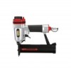
SAFETy Functional Description Specifications Maximum Air Pressure Air Inlet Air Consumption Safety Mechanism Type Staple Type 120 PSI 1/4″ -18 NPT 0.5 CFM @ 90 PSI Single Sequential 18 Gauge, 5/8″-1-1/2″ Long, 1/4″ Crown SETUp OpERATION MAINTENANcE Item 69719 For technical questions, please call 1-800-444-3353. Page 7
SAFETy Functional Description Specifications Maximum Air Pressure Air Inlet Air Consumption Safety Mechanism Type Staple Type 120 PSI 1/4″ -18 NPT 0.5 CFM @ 90 PSI Single Sequential 18 Gauge, 5/8″-1-1/2″ Long, 1/4″ Crown SETUp OpERATION MAINTENANcE Item 69719 For technical questions, please call 1-800-444-3353. Page 7

User Manual
Page 8
SAFETy components and controls Air Deflector Driver Guide Trigger Air Inlet Plug Magazine Release Safety Nosepiece Magazine Safety Nosepiece - Item 69719 SETUp OpERATION MAINTENANcE Page 8 For technical questions, please call 1-800-444-3353. Also called the workpiece contact, the Safety Nosepiece helps prevent the tool from firing unless it is pressed against an object.
SAFETy components and controls Air Deflector Driver Guide Trigger Air Inlet Plug Magazine Release Safety Nosepiece Magazine Safety Nosepiece - Item 69719 SETUp OpERATION MAINTENANcE Page 8 For technical questions, please call 1-800-444-3353. Also called the workpiece contact, the Safety Nosepiece helps prevent the tool from firing unless it is pressed against an object.
User Manual
Page 9
... air supply components. 3. Turn on the air compressor according to set up or use oxygen, carbon dioxide, combustible gases, or any leaks found. 10. Adjust the air compressor's output regulator so that have a thickness of less than 1-3/4″. 9. Adjust the pressure gradually, while checking the air output gauge to the manufacturer's directions and allow free movement while working. 4. Note: Residual air pressure should be a ball valve because it is a good safety...
... air supply components. 3. Turn on the air compressor according to set up or use oxygen, carbon dioxide, combustible gases, or any leaks found. 10. Adjust the air compressor's output regulator so that have a thickness of less than 1-3/4″. 9. Adjust the pressure gradually, while checking the air output gauge to the manufacturer's directions and allow free movement while working. 4. Note: Residual air pressure should be a ball valve because it is a good safety...

User Manual
Page 10
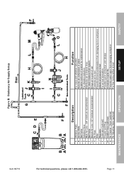
... and Plug F Leader Hose (optional) G Air Cleaner / Dryer (optional) H Air Adjusting Valve (optional) C EH G A Function Connects air to tool Prevents dirt and condensation from damaging tool or workpiece Adjusts air pressure to tool For air tool lubrication Provides quick connection and release Increases coupler life Prevents water vapor from damaging workpiece For fine tuning airflow at tool Item 69719 SAFETy SETUp OpERATION MAINTENANcE Page 10 Figure A: portable Air Supply Setup Lubricated Tools BC D A E F A For technical...
... and Plug F Leader Hose (optional) G Air Cleaner / Dryer (optional) H Air Adjusting Valve (optional) C EH G A Function Connects air to tool Prevents dirt and condensation from damaging tool or workpiece Adjusts air pressure to tool For air tool lubrication Provides quick connection and release Increases coupler life Prevents water vapor from damaging workpiece For fine tuning airflow at tool Item 69719 SAFETy SETUp OpERATION MAINTENANcE Page 10 Figure A: portable Air Supply Setup Lubricated Tools BC D A E F A For technical...
User Manual
Page 11
... drain moisture from system Brings air to point of use Connects air to tool Prevents dirt and condensation from damaging tool or workpiece Adjusts air pressure to tool For air tool lubrication Provides quick connection and release Increases coupler life Prevents water vapor from damaging workpiece For fine tuning airflow at tool MAINTENANcE OpERATION SETUp SAFETy Page 11 Figure B: Stationary Air Supply Setup Item 69719 For technical questions, please call...
... drain moisture from system Brings air to point of use Connects air to tool Prevents dirt and condensation from damaging tool or workpiece Adjusts air pressure to tool For air tool lubrication Provides quick connection and release Increases coupler life Prevents water vapor from damaging workpiece For fine tuning airflow at tool MAINTENANcE OpERATION SETUp SAFETy Page 11 Figure B: Stationary Air Supply Setup Item 69719 For technical questions, please call...

User Manual
Page 12
..., loose, and missing parts. Route the air hose along a safe route to prevent movement while working . 3. Secure loose workpieces using a vise or clamps (not included) to reach the work area that is clean and well-lit. Check that will present a hazard while working. If the tool fires, stop immediately and have it repaired by a qualified service technician. 7. Release the Trigger and squeeze it against...
..., loose, and missing parts. Route the air hose along a safe route to prevent movement while working . 3. Secure loose workpieces using a vise or clamps (not included) to reach the work area that is clean and well-lit. Check that will present a hazard while working. If the tool fires, stop immediately and have it repaired by a qualified service technician. 7. Release the Trigger and squeeze it against...

User Manual
Page 13
... use . Rotate Air Deflector to accomplish the task, verify that it is disconnected and is incapable of this tool. 2. Attempt to fire the Tool into a piece of Pneumatic Tool Oil to prevent accidents: a. TO pREVENT INJURy FROM TOOL OR AccESSORy FAILURE: Do not exceed the tool's maximum air pressure rating. SAFETy SETUp Loading the Tool TO pREVENT SERIOUS INJURy FROM AccIDENTAL OpERATION, BEFORE LOADING: • Wear ANSI-approved safety...
... use . Rotate Air Deflector to accomplish the task, verify that it is disconnected and is incapable of this tool. 2. Attempt to fire the Tool into a piece of Pneumatic Tool Oil to prevent accidents: a. TO pREVENT INJURy FROM TOOL OR AccESSORy FAILURE: Do not exceed the tool's maximum air pressure rating. SAFETy SETUp Loading the Tool TO pREVENT SERIOUS INJURy FROM AccIDENTAL OpERATION, BEFORE LOADING: • Wear ANSI-approved safety...
User Manual
Page 14
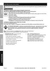
... air is detected, have the problem corrected before further use damaged equipment. Other lubricants may damage the mechanism and may be performed only by a qualified technician. Maintain the lubricator's oil level. Performing routine maintenance on the air supply will also reduce wear on the air supply according to fly out of the Tool. SAFETy User-Maintenance Instructions procedures not specifically explained in this manual...
... air is detected, have the problem corrected before further use damaged equipment. Other lubricants may damage the mechanism and may be performed only by a qualified technician. Maintain the lubricator's oil level. Performing routine maintenance on the air supply will also reduce wear on the air supply according to fly out of the Tool. SAFETy User-Maintenance Instructions procedures not specifically explained in this manual...
User Manual
Page 15
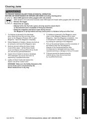
... the tool serviced by a qualified technician. Lightly oil Driver Guide and replace the Spacer and Driver Guide Cover. Open the Magazine completely. WARNING! SAFETy clearing Jams TO pREVENT SERIOUS INJURy FROM AccIDENTAL OpERATION, BEFORE ANy MAINTENANcE OR REpAIRS ARE DONE (including clearing jams): • Wear ANSI-approved safety goggles with side shields. • Release the trigger. • Detach the air supply. • Attempt to fire the Tool into a piece...
... the tool serviced by a qualified technician. Lightly oil Driver Guide and replace the Spacer and Driver Guide Cover. Open the Magazine completely. WARNING! SAFETy clearing Jams TO pREVENT SERIOUS INJURy FROM AccIDENTAL OpERATION, BEFORE ANy MAINTENANcE OR REpAIRS ARE DONE (including clearing jams): • Wear ANSI-approved safety goggles with side shields. • Release the trigger. • Detach the air supply. • Attempt to fire the Tool into a piece...
User Manual
Page 16
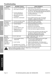
..., especially on older tools.) possible causes 1. Tighten housing assembly. Incorrect tool depth setting. 2. Incorrect tool depth setting. 2. Insufficient air flow. Adjust depth setting, if available. 2. Clean air inlet screen of buildup. 5. Confirm staple gauge, crown, type, and length. Replace damaged components. 4. OpERATION MAINTENANcE Page 16 For technical questions, please call 1-800-444-3353. Item 69719 Fasteners drive too deeply. Not enough air pressure. 3. Jammed fastener. 2. Damaged valve or housing. 4. Do not exceed maximum air pressure. 3. Have qualified...
..., especially on older tools.) possible causes 1. Tighten housing assembly. Incorrect tool depth setting. 2. Incorrect tool depth setting. 2. Insufficient air flow. Adjust depth setting, if available. 2. Clean air inlet screen of buildup. 5. Confirm staple gauge, crown, type, and length. Replace damaged components. 4. OpERATION MAINTENANcE Page 16 For technical questions, please call 1-800-444-3353. Item 69719 Fasteners drive too deeply. Not enough air pressure. 3. Jammed fastener. 2. Damaged valve or housing. 4. Do not exceed maximum air pressure. 3. Have qualified...
User Manual
Page 17
... IS QUALIFIED TO REPLACE ANY PARTS OF THE PRODUCT. SETUp OpERATION MAINTENANcE Item 69719 For technical questions, please call 1-800-444-3353. SAFETy parts List and Diagram pLEASE READ THE FOLLOWING cAREFULLy THE MANUFACTURER AND/OR DISTRIBUTOR HAS PROVIDED THE PARTS LIST AND ASSEMBLY DIAGRAM IN THIS MANUAL AS A REFERENCE TOOL ONLY. IN FACT, THE MANUFACTURER AND/OR DISTRIBUTOR EXPRESSLY STATES THAT ALL REPAIRS AND PARTS REPLACEMENTS SHOULD BE...
... IS QUALIFIED TO REPLACE ANY PARTS OF THE PRODUCT. SETUp OpERATION MAINTENANcE Item 69719 For technical questions, please call 1-800-444-3353. SAFETy parts List and Diagram pLEASE READ THE FOLLOWING cAREFULLy THE MANUFACTURER AND/OR DISTRIBUTOR HAS PROVIDED THE PARTS LIST AND ASSEMBLY DIAGRAM IN THIS MANUAL AS A REFERENCE TOOL ONLY. IN FACT, THE MANUFACTURER AND/OR DISTRIBUTOR EXPRESSLY STATES THAT ALL REPAIRS AND PARTS REPLACEMENTS SHOULD BE...
User Manual
Page 18
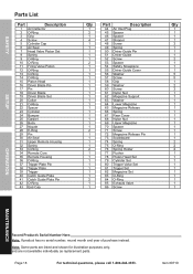
... Screw 61 Nylon Nut 62 Magazine Support 63 Washer 64 Lower Magazine 65 Magazine Release 66 Spring 67 Rear Cover 68 Nylon Nut 69 Upper Magazine 70 Spacer 71 Screw 72 Magazine Release Pin 73 Scaleboard 74 Spring 75 O-Ring 76 Spring Holder 77 Pusher 78 Piston Head Set 79 Cylinder Set 80 Trigger Valve Set 81 Trigger Set 82 Magazine Set 83 O-Ring 84 O-Ring 85 Exhaust Valve 86 Screw Qty 1 1 1 1 2 1 1 1 2 1 1 1 5 5 1 2 2 1 1 1 1 1 1 1 1 1 1 1 1 1 2 2 2 1 1 1 1 1 1 1 1 1 1 OpERATION MAINTENANcE Record product's Serial Number...
... Screw 61 Nylon Nut 62 Magazine Support 63 Washer 64 Lower Magazine 65 Magazine Release 66 Spring 67 Rear Cover 68 Nylon Nut 69 Upper Magazine 70 Spacer 71 Screw 72 Magazine Release Pin 73 Scaleboard 74 Spring 75 O-Ring 76 Spring Holder 77 Pusher 78 Piston Head Set 79 Cylinder Set 80 Trigger Valve Set 81 Trigger Set 82 Magazine Set 83 O-Ring 84 O-Ring 85 Exhaust Valve 86 Screw Qty 1 1 1 1 2 1 1 1 2 1 1 1 5 5 1 2 2 1 1 1 1 1 1 1 1 1 1 1 1 1 2 2 2 1 1 1 1 1 1 1 1 1 1 OpERATION MAINTENANcE Record product's Serial Number...
User Manual
Page 19
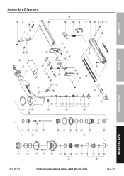
Page 19 For technical questions, please call 1-800-444-3353. Item 69719 1 2 3 4 5 6 84 7 85 8 9 10 11 78 12 83 14 15 19 16 17 18 20 21 22 10 13 79 23 24 MAINTENANcE 25 28 26 27 30 31 32 33 80 34 33 35 36 37 81 38 39 44 43 60 42 56 58 29 45 46 47 59 48 40 41 49 55 56 57 74 50 51 52 53 54 28 75 76 77 57 50 40 30 20 10 LOAD 61 62 63 86 64 65 82 66 67 68 69 70 71 72 73 OpERATION SETUp SAFETy Assembly Diagram
Page 19 For technical questions, please call 1-800-444-3353. Item 69719 1 2 3 4 5 6 84 7 85 8 9 10 11 78 12 83 14 15 19 16 17 18 20 21 22 10 13 79 23 24 MAINTENANcE 25 28 26 27 30 31 32 33 80 34 33 35 36 37 81 38 39 44 43 60 42 56 58 29 45 46 47 59 48 40 41 49 55 56 57 74 50 51 52 53 54 28 75 76 77 57 50 40 30 20 10 LOAD 61 62 63 86 64 65 82 66 67 68 69 70 71 72 73 OpERATION SETUp SAFETy Assembly Diagram

User Manual
Page 20
Limited 90 Day Warranty Harbor Freight Tools Co. THIS WARRANTY IS EXPRESSLY IN LIEU OF ALL OTHER WARRANTIES, EXPRESS OR IMPLIED, INCLUDING THE WARRANTIES OF MERCHANTABILITY AND FITNESS. We will either repair or replace the product at our expense, but if we determine there is free from defects in no defect, or that ... purchase price if we may also have other rights which vary from the use of this product is no event be returned to the original purchaser that this warranty, the product or part must accompany the merchandise. To take advantage of our product. makes every...
Limited 90 Day Warranty Harbor Freight Tools Co. THIS WARRANTY IS EXPRESSLY IN LIEU OF ALL OTHER WARRANTIES, EXPRESS OR IMPLIED, INCLUDING THE WARRANTIES OF MERCHANTABILITY AND FITNESS. We will either repair or replace the product at our expense, but if we determine there is free from defects in no defect, or that ... purchase price if we may also have other rights which vary from the use of this product is no event be returned to the original purchaser that this warranty, the product or part must accompany the merchandise. To take advantage of our product. makes every...


