User Manual
Page 2
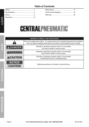
SAFETY Table of Contents Safety 3 Specifications 6 Setup 6 Operation 12 Maintenance 14 Parts List and Diagram 18 Warranty 20 WARNING SYMBOLS AND DEFINITIONS This is used to alert you to potential personal injury hazards. SETUP OPERATION MAINTENANCE Page 2 For technical questions, please call 1-800-444-3353. Indicates a hazardous situation which , if not avoided, could result in death or serious injury. Obey all safety... in death or serious injury. Item 61693 It is the safety alert symbol. Indicates a hazardous situation which , if not avoided, will ...
SAFETY Table of Contents Safety 3 Specifications 6 Setup 6 Operation 12 Maintenance 14 Parts List and Diagram 18 Warranty 20 WARNING SYMBOLS AND DEFINITIONS This is used to alert you to potential personal injury hazards. SETUP OPERATION MAINTENANCE Page 2 For technical questions, please call 1-800-444-3353. Indicates a hazardous situation which , if not avoided, could result in death or serious injury. Obey all safety... in death or serious injury. Item 61693 It is the safety alert symbol. Indicates a hazardous situation which , if not avoided, will ...

User Manual
Page 3
... cords increase the risk of electric shock. Do not use . Such preventive safety measures reduce the risk of parts and any adjustments, changing accessories, or storing the compressor. Check for operations different from those intended could result in the presence of untrained users. Have your compressor serviced by a poorly maintained compressor. Page 3 Compressor motors produce sparks which cannot be built into account the working conditions and the work...
... cords increase the risk of electric shock. Do not use . Such preventive safety measures reduce the risk of parts and any adjustments, changing accessories, or storing the compressor. Check for operations different from those intended could result in the presence of untrained users. Have your compressor serviced by a poorly maintained compressor. Page 3 Compressor motors produce sparks which cannot be built into account the working conditions and the work...
User Manual
Page 4
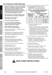
... daily and after working pressure of 150 PSI, or 150% of California to the State of the maximum system pressure, whichever is in close proximity to use depending on the compressor. Add correct amount of injury - Compressor head gets hot during or immediately following guidelines: TABLE A: RECOMMENDED MINIMUM WIRE GAUGE FOR EXTENSION CORDS (120 VOLT) NAMEPLATE AMPERES (at full load) EXTENSION CORD LENGTH 25′...
... daily and after working pressure of 150 PSI, or 150% of California to the State of the maximum system pressure, whichever is in close proximity to use depending on the compressor. Add correct amount of injury - Compressor head gets hot during or immediately following guidelines: TABLE A: RECOMMENDED MINIMUM WIRE GAUGE FOR EXTENSION CORDS (120 VOLT) NAMEPLATE AMPERES (at full load) EXTENSION CORD LENGTH 25′...
User Manual
Page 5
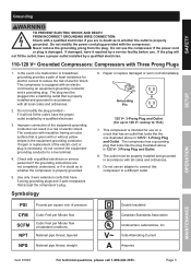
...-3353. Grounding SAFETY SETUP OPERATION TO PREVENT ELECTRIC SHOCK AND DEATH FROM INCORRECT GROUNDING WIRE CONNECTION: Check with a qualified electrician or service personnel if the grounding instructions are in doubt as to whether the compressor is properly grounded. 5. The compressor has a grounding plug that accept the compressor's plug. 6. If repair or replacement of electric shock. Repair or replace damaged or worn cord immediately. Grounding Pin 125 V~ 3-Prong Plug...
...-3353. Grounding SAFETY SETUP OPERATION TO PREVENT ELECTRIC SHOCK AND DEATH FROM INCORRECT GROUNDING WIRE CONNECTION: Check with a qualified electrician or service personnel if the grounding instructions are in doubt as to whether the compressor is properly grounded. 5. The compressor has a grounding plug that accept the compressor's plug. 6. If repair or replacement of electric shock. Repair or replace damaged or worn cord immediately. Grounding Pin 125 V~ 3-Prong Plug...
User Manual
Page 6
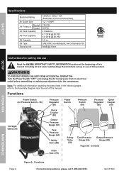
... under subheadings therein before assembling or making any adjustments to the Assembly Diagram near the end of this manual. Note: For additional information regarding the parts listed in the following pages, refer to the compressor. Item 61693 MAINTENANCE SAE 30W, non-detergent, Air Compressor Oil 90dB @ 3 feet 4001244 SETUP OPERATION Instructions for putting into use of this product. Functions Power Switch (on Pressure Switch - 58) Pressure Regulator (56) Power Switch Pressure Switch (58) Pressure Regulator (56) Quick...
... under subheadings therein before assembling or making any adjustments to the Assembly Diagram near the end of this manual. Note: For additional information regarding the parts listed in the following pages, refer to the compressor. Item 61693 MAINTENANCE SAE 30W, non-detergent, Air Compressor Oil 90dB @ 3 feet 4001244 SETUP OPERATION Instructions for putting into use of this product. Functions Power Switch (on Pressure Switch - 58) Pressure Regulator (56) Power Switch Pressure Switch (58) Pressure Regulator (56) Quick...
User Manual
Page 7
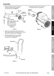
... of the Cylinder Head (7). Tank (68) Nut (72) Spring Washer (71) Axle (69) 4. See Figure C. Slide the Handle (67) into the two fittings on the Tank and secure it in place with four Bolts (66). Cylinder Head (7) Air Filter (8) Nut (79) Spring Washer (78) Washer (77) Foot Pad (76) Washer (75) Bolt (74) Wheel (70) Figure C 2. Figure E Handle (67) SETUP OPERATION Tank Figure D Bolt (66) MAINTENANCE Item 61693 For technical...
... of the Cylinder Head (7). Tank (68) Nut (72) Spring Washer (71) Axle (69) 4. See Figure C. Slide the Handle (67) into the two fittings on the Tank and secure it in place with four Bolts (66). Cylinder Head (7) Air Filter (8) Nut (79) Spring Washer (78) Washer (77) Foot Pad (76) Washer (75) Bolt (74) Wheel (70) Figure C 2. Figure E Handle (67) SETUP OPERATION Tank Figure D Bolt (66) MAINTENANCE Item 61693 For technical...
User Manual
Page 8
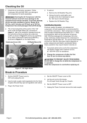
... instead whenever the compressor's temperature will expel freely through the Coupler. 6. To add oil: a. Set the ON/OFF Power Lever to avoid spills, pour enough oil into the Quick Coupler (55) and fully open all regulators and valves. 3. OPERATION MAINTENANCE Page 8 For technical questions, please call Harbor Freight Tools customer service at the center of use multi-viscosity oil (such as needed to ON. 5. SAFETY SETUP Checking the...
... instead whenever the compressor's temperature will expel freely through the Coupler. 6. To add oil: a. Set the ON/OFF Power Lever to avoid spills, pour enough oil into the Quick Coupler (55) and fully open all regulators and valves. 3. OPERATION MAINTENANCE Page 8 For technical questions, please call Harbor Freight Tools customer service at the center of use multi-viscosity oil (such as needed to ON. 5. SAFETY SETUP Checking the...
User Manual
Page 9
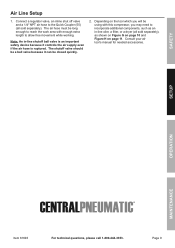
... quickly. 2. Consult your air tool's manual for needed accessories. Depending on the tool which you may need to allow free movement while working. Connect a regulator valve, an inline shut off valve and a 1/4″ NPT air hose to the Quick Coupler (55) (all sold separately). The shutoff valve should be a ball valve because it controls the air supply even if the air hose is ruptured. SAFETY SETUP OPERATION MAINTENANCE Item 61693 For technical questions...
... quickly. 2. Consult your air tool's manual for needed accessories. Depending on the tool which you may need to allow free movement while working. Connect a regulator valve, an inline shut off valve and a 1/4″ NPT air hose to the Quick Coupler (55) (all sold separately). The shutoff valve should be a ball valve because it controls the air supply even if the air hose is ruptured. SAFETY SETUP OPERATION MAINTENANCE Item 61693 For technical questions...
User Manual
Page 10
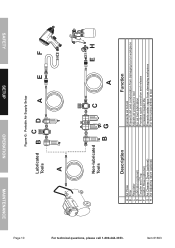
SAFETY SETUP OPERATION MAINTENANCE Page 10 Figure G: Portable Air Supply Setup Lubricated Tools BC D A E F A For technical questions, please call 1-800-444-3353. Non-lubricated Tools C EH BG A Description A Air Hose B Filter C Regulator D Lubricator (optional) E Coupler and Plug F Leader Hose (optional) G Air Cleaner / Dryer (optional) H Air Adjusting Valve (optional) Function Connects air to tool Prevents dirt and condensation from damaging tool or workpiece Adjusts air pressure to tool For air tool lubrication Provides quick connection and release Increases...
SAFETY SETUP OPERATION MAINTENANCE Page 10 Figure G: Portable Air Supply Setup Lubricated Tools BC D A E F A For technical questions, please call 1-800-444-3353. Non-lubricated Tools C EH BG A Description A Air Hose B Filter C Regulator D Lubricator (optional) E Coupler and Plug F Leader Hose (optional) G Air Cleaner / Dryer (optional) H Air Adjusting Valve (optional) Function Connects air to tool Prevents dirt and condensation from damaging tool or workpiece Adjusts air pressure to tool For air tool lubrication Provides quick connection and release Increases...

User Manual
Page 11
... drain moisture from system Brings air to point of use Connects air to tool Prevents dirt and condensation from damaging tool or workpiece Adjusts air pressure to tool For air tool lubrication Provides quick connection and release Increases coupler life Prevents water vapor from damaging workpiece For fine tuning airflow at tool MAINTENANCE OPERATION SETUP SAFETY Page 11 Figure H: Stationary Air Supply Setup Item 61693 For technical questions, please call...
... drain moisture from system Brings air to point of use Connects air to tool Prevents dirt and condensation from damaging tool or workpiece Adjusts air pressure to tool For air tool lubrication Provides quick connection and release Increases coupler life Prevents water vapor from damaging workpiece For fine tuning airflow at tool MAINTENANCE OPERATION SETUP SAFETY Page 11 Figure H: Stationary Air Supply Setup Item 61693 For technical questions, please call...

User Manual
Page 12
... change to the automatic pressure levels may cause excess pressure to operate too often, increasing wear. Unplug the Air Compressor. 13. SAFETY SETUP Operating Instructions Read the ENTIRE IMPORTANT SAFETY INFORMATION section at any built-up pressure until it clockwise. (See Draining Moisture from the tool then disconnect the tool. 15. Designate a work area must not allow air circulation. 3. Plug the Power Cord into a grounded 120VAC electrical outlet. 5. Turn the Power Switch...
... change to the automatic pressure levels may cause excess pressure to operate too often, increasing wear. Unplug the Air Compressor. 13. SAFETY SETUP Operating Instructions Read the ENTIRE IMPORTANT SAFETY INFORMATION section at any built-up pressure until it clockwise. (See Draining Moisture from the tool then disconnect the tool. 15. Designate a work area must not allow air circulation. 3. Plug the Power Cord into a grounded 120VAC electrical outlet. 5. Turn the Power Switch...

User Manual
Page 13
... avoid damage to quickly depressurize the Compressor, turn the Power Switch OFF. Correct any issues before reaching its own, press the Reset Button to quickly release stored air pressure. Possible causes of the Air Compressor are: • Using an extension cord that is necessary to the compressor. Then, pull on the ring on its normal cutoff pressure: a. c. See Figure I SETUP OPERATION MAINTENANCE Item 61693 For technical questions, please call...
... avoid damage to quickly depressurize the Compressor, turn the Power Switch OFF. Correct any issues before reaching its own, press the Reset Button to quickly release stored air pressure. Possible causes of the Air Compressor are: • Using an extension cord that is necessary to the compressor. Then, pull on the ring on its normal cutoff pressure: a. c. See Figure I SETUP OPERATION MAINTENANCE Item 61693 For technical questions, please call...

User Manual
Page 14
... electrical outlet before further use damaged equipment. Note: The environment in this compressor is damaged, it must be replaced only by a qualified technician. Daily: a. Check for air leaks.* g. b. TO PREVENT SERIOUS INJURY FROM ACCIDENTAL OPERATION: Turn the Power Switch "OFF" and unplug the Compressor from its safe operation. 2. Check oil level. c. e. Look for maintenance checks of this manual must be performed only by a qualified service...
... electrical outlet before further use damaged equipment. Note: The environment in this compressor is damaged, it must be replaced only by a qualified technician. Daily: a. Check for air leaks.* g. b. TO PREVENT SERIOUS INJURY FROM ACCIDENTAL OPERATION: Turn the Power Switch "OFF" and unplug the Compressor from its safe operation. 2. Check oil level. c. e. Look for maintenance checks of this manual must be performed only by a qualified service...

User Manual
Page 15
....). 6. Replace and tighten the Oil Breather Plug. 7. Drain Valve Open Tank Drain Valve Lever Drain Valve Closed Tank Drain Valve Lever 3. Page 15 Discard the old oil according to cool before changing the oil. 1. It must be used daily to release all the pressure and moisture has been released, close the Drain Valve by moving the Drain Valve Lever perpendicular to replace the oil more frequently. Turn the Power Switch OFF. 2. This will need to...
....). 6. Replace and tighten the Oil Breather Plug. 7. Drain Valve Open Tank Drain Valve Lever Drain Valve Closed Tank Drain Valve Lever 3. Page 15 Discard the old oil according to cool before changing the oil. 1. It must be used daily to release all the pressure and moisture has been released, close the Drain Valve by moving the Drain Valve Lever perpendicular to replace the oil more frequently. Turn the Power Switch OFF. 2. This will need to...

User Manual
Page 16
... 1-800-444-3353. SAFETY SETUP Troubleshooting Problem Compressor does not start when needed . Incorrect power supply. 4. Extension cord wire size is too small or cord is met by Compressor. Working environment too cold. 4. Crankcase oil too thick. 7. Press reset button. If leaking, replace with identical valve with greater output. 1. Reposition unit on level surface. 3. Clean Crankcase vent. Power cord not plugged in securely. 3. No power at outlet. 5. Compressor needs service. 1. Incorrect power supply. 2. Compressor not large enough...
... 1-800-444-3353. SAFETY SETUP Troubleshooting Problem Compressor does not start when needed . Incorrect power supply. 4. Extension cord wire size is too small or cord is met by Compressor. Working environment too cold. 4. Crankcase oil too thick. 7. Press reset button. If leaking, replace with identical valve with greater output. 1. Reposition unit on level surface. 3. Clean Crankcase vent. Power cord not plugged in securely. 3. No power at outlet. 5. Compressor needs service. 1. Incorrect power supply. 2. Compressor not large enough...

User Manual
Page 17
... PARTS LIST AND ASSEMBLY DIAGRAM IN THIS MANUAL AS A REFERENCE TOOL ONLY. THE BUYER ASSUMES ALL RISK AND LIABILITY ARISING OUT OF HIS OR HER REPAIRS TO THE ORIGINAL PRODUCT OR REPLACEMENT PARTS THERETO, OR ARISING OUT OF HIS OR HER INSTALLATION OF REPLACEMENT PARTS THERETO. Compressor not large enough for leaks. 3. Loose fittings. 4. Crankcase vents clogged. Safety valve needs service. Likely Solutions 1. Clean and/or replace as needed...
... PARTS LIST AND ASSEMBLY DIAGRAM IN THIS MANUAL AS A REFERENCE TOOL ONLY. THE BUYER ASSUMES ALL RISK AND LIABILITY ARISING OUT OF HIS OR HER REPAIRS TO THE ORIGINAL PRODUCT OR REPLACEMENT PARTS THERETO, OR ARISING OUT OF HIS OR HER INSTALLATION OF REPLACEMENT PARTS THERETO. Compressor not large enough for leaks. 3. Loose fittings. 4. Crankcase vents clogged. Safety valve needs service. Likely Solutions 1. Clean and/or replace as needed...

User Manual
Page 18
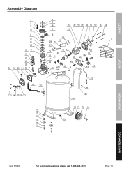
... Ø14 Spring Washer Ø5 Bolt M5 x 115 Quick Coupler Pressure Regulator Connector Pressure Switch Safety Valve Unloader Tube Exhaust Tube Check Valve Output Pressure Gauge Tank Pressure Gauge Plug Bolt M6 x 10 Handle Tank Axle Wheel Spring Washer Ø10 Nut M10 Drain Valve Bolt M8 x 25 Plain Washer Ø8 x Ø24 x 2 Foot Pad Plain Washer Ø8 Spring Washer Ø8 Nut M8 Qty 1 1 1 1 1 1 1 1 1 1 1 1 4 4 1 1 1 1 1 1 1 1 1 1 1 1 1 1 2 2 2 2 1 2 2 2 2 2 2 OPERATION MAINTENANCE Record Product's Serial Number Here: Note: If product has no serial number, record month...
... Ø14 Spring Washer Ø5 Bolt M5 x 115 Quick Coupler Pressure Regulator Connector Pressure Switch Safety Valve Unloader Tube Exhaust Tube Check Valve Output Pressure Gauge Tank Pressure Gauge Plug Bolt M6 x 10 Handle Tank Axle Wheel Spring Washer Ø10 Nut M10 Drain Valve Bolt M8 x 25 Plain Washer Ø8 x Ø24 x 2 Foot Pad Plain Washer Ø8 Spring Washer Ø8 Nut M8 Qty 1 1 1 1 1 1 1 1 1 1 1 1 4 4 1 1 1 1 1 1 1 1 1 1 1 1 1 1 2 2 2 2 1 2 2 2 2 2 2 OPERATION MAINTENANCE Record Product's Serial Number Here: Note: If product has no serial number, record month...
User Manual
Page 19
Assembly Diagram SAFETY SETUP OPERATION MAINTENANCE Item 61693 For technical questions, please call 1-800-444-3353. Page 19
Assembly Diagram SAFETY SETUP OPERATION MAINTENANCE Item 61693 For technical questions, please call 1-800-444-3353. Page 19
User Manual
Page 20
...due directly or indirectly, to misuse, abuse, negligence or accidents, repairs or alterations outside our facilities, criminal activity, improper installation, normal wear and tear, or to refund the purchase price if we may also have other rights which vary from the use of returning the product. To take advantage of maintenance. This warranty gives you specific ... elect to lack of this product is no event be liable for incidental, contingent, special or consequential damages arising from state to us with a replacement. Limited 90 Day Warranty Harbor Freight Tools Co.
...due directly or indirectly, to misuse, abuse, negligence or accidents, repairs or alterations outside our facilities, criminal activity, improper installation, normal wear and tear, or to refund the purchase price if we may also have other rights which vary from the use of returning the product. To take advantage of maintenance. This warranty gives you specific ... elect to lack of this product is no event be liable for incidental, contingent, special or consequential damages arising from state to us with a replacement. Limited 90 Day Warranty Harbor Freight Tools Co.


