User Manual
Page 3
... these numbers for future use any electrical switch; Contents Important Safeguards 4-8 Energy Saving Ideas 8 Installation Instructions 9-10 Backguard Installation 11 Wall Clearances 12 Alignments and Adjustments 13-20 Operation of Range 21-23 Broiling 23 Optional Equipment 24-25 Cleaning the Range 26-27 Lift-Off Doors 28 Trouble Shooting Guide 29 Wiring Diagrams 30-31 Note: For warranty and service information, please see back cover of sale. and Serial No. Follow the gas supplier's instructions...
... these numbers for future use any electrical switch; Contents Important Safeguards 4-8 Energy Saving Ideas 8 Installation Instructions 9-10 Backguard Installation 11 Wall Clearances 12 Alignments and Adjustments 13-20 Operation of Range 21-23 Broiling 23 Optional Equipment 24-25 Cleaning the Range 26-27 Lift-Off Doors 28 Trouble Shooting Guide 29 Wiring Diagrams 30-31 Note: For warranty and service information, please see back cover of sale. and Serial No. Follow the gas supplier's instructions...
User Manual
Page 4
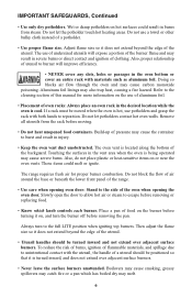
... THE RANGE, THE RANGE MUST BE SECURED BY A PROPERLY INSTALLED ANTI-TIP BRACKET PROVIDED WITH THE RANGE. Birds have a very sensitive respiratory system. Ask your appliance is caused primarily from the carton. Children climbing on the backguard of natural gas or LP fuel. READ ALL IMPORTANT SAFEGUARDS AND ALL INSTRUCTIONS BEFORE USING THE APPLIANCE. Remove all tape and packaging wrap before using this new appliance, carefully...
... THE RANGE, THE RANGE MUST BE SECURED BY A PROPERLY INSTALLED ANTI-TIP BRACKET PROVIDED WITH THE RANGE. Birds have a very sensitive respiratory system. Ask your appliance is caused primarily from the carton. Children climbing on the backguard of natural gas or LP fuel. READ ALL IMPORTANT SAFEGUARDS AND ALL INSTRUCTIONS BEFORE USING THE APPLIANCE. Remove all tape and packaging wrap before using this new appliance, carefully...
User Manual
Page 5
... alter the construction of this owner's guide. Do not remove leveling legs, panels, wire covers, anti-tip brackets or any unused range if it closely. Do not store explosives, such as aerosol cans, on or near the range. • Remove the oven door from any other flammable materials contact surface burners or interior surfaces of the oven until they have had sufficient time to heat or warm the ! CAUTION The following situations...
... alter the construction of this owner's guide. Do not remove leveling legs, panels, wire covers, anti-tip brackets or any unused range if it closely. Do not store explosives, such as aerosol cans, on or near the range. • Remove the oven door from any other flammable materials contact surface burners or interior surfaces of the oven until they have had sufficient time to heat or warm the ! CAUTION The following situations...
User Manual
Page 6
... cover an entire rack with both hands to unintentional contact with the utensil, the handle of food on the use potholders and grasp the rack with materials such as aluminum foil. Place a pan of a utensil should be moved when the oven is being operated may catch fire or a pan which knob controls each burner. Slowly open the door to allow hot air or steam to the cleaning...
... cover an entire rack with both hands to unintentional contact with the utensil, the handle of food on the use potholders and grasp the rack with materials such as aluminum foil. Place a pan of a utensil should be moved when the oven is being operated may catch fire or a pan which knob controls each burner. Slowly open the door to allow hot air or steam to the cleaning...
User Manual
Page 7
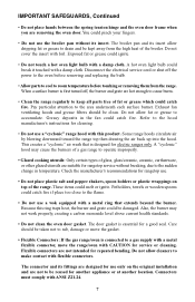
... gas range/oven is first turned off the power to the oven before removing and replacing the bulb. • Allow parts to cool to make contact with CAUTION for service or cleaning. The door gasket is designed for electric ranges only. Care should be reused for cleaning. • Do not use only on top of the range. Pay particular attention to accumulate. Also, the burner may cause the burners of a gas range to operate...
... gas range/oven is first turned off the power to the oven before removing and replacing the bulb. • Allow parts to cool to make contact with CAUTION for service or cleaning. The door gasket is designed for electric ranges only. Care should be reused for cleaning. • Do not use only on top of the range. Pay particular attention to accumulate. Also, the burner may cause the burners of a gas range to operate...

User Manual
Page 8
... metals that match the flame size. Thawed food requires less cooking energy than frozen food. WARNING burners without the cooktop, burner caps, and ignition wires firmly in this owner's guide are cooked. Choose pans made of a house fire. • Disconnect the range from electrical supply before attempting to service or move it. Make it a habit to check on the oven. There is half-cooked, and then warm rolls or dessert...
... metals that match the flame size. Thawed food requires less cooking energy than frozen food. WARNING burners without the cooktop, burner caps, and ignition wires firmly in this owner's guide are cooked. Choose pans made of a house fire. • Disconnect the range from electrical supply before attempting to service or move it. Make it a habit to check on the oven. There is half-cooked, and then warm rolls or dessert...
User Manual
Page 10
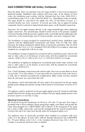
... will ground the range when plugged into the special terminal block located at the top of such codes, with the National Fuel Gas Code, ANSI Z223.1Latest Edition in the absence of the main back directly under the backguard supply cord. The installation of ranges designed for manufactured (mobile) home installation must be connected to the supply line with a three-conductor (three-prong plug) supply cord which is not impossible...
... will ground the range when plugged into the special terminal block located at the top of such codes, with the National Fuel Gas Code, ANSI Z223.1Latest Edition in the absence of the main back directly under the backguard supply cord. The installation of ranges designed for manufactured (mobile) home installation must be connected to the supply line with a three-conductor (three-prong plug) supply cord which is not impossible...
User Manual
Page 11
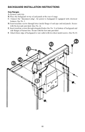
C. Connect the "disconnect plug", for power to vent outlet with electrical features. Secure with the hex nuts provided. Remove main top. D. Insert machine screws through lower inside flange of range. F. E. Insert machine screws through elongated holes (See No. 3) at the rear of end caps and end panels. Place the backguard on top of end panels at bottom of backguard and side flanges of backguard to...
C. Connect the "disconnect plug", for power to vent outlet with electrical features. Secure with the hex nuts provided. Remove main top. D. Insert machine screws through lower inside flange of range. F. E. Insert machine screws through elongated holes (See No. 3) at the rear of end caps and end panels. Place the backguard on top of end panels at bottom of backguard and side flanges of backguard to...
User Manual
Page 13
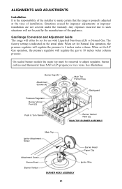
Burner Cap (4) Attachment Screws (4) Pressure Regulator Burner Venturi Front (2) Main Top Partial View Backguard Push & Turn Valves Burner Venturi Rear (2) MAIN TOP /BURNER ASSEMBLY Main Top Ignitor Attachment Screw Attachment Screw Burner Bowl Burner Venturi BURNER HEAD ASSEMBLY Burner Head Paper Clip Ignitor Wire 13 Situations caused by the manufacturer of the appliance. When set for LP Gas operation, the pressure regulator will regulate the gas to 10 inches water column pressure. Gas Range Conversion and Adjustment Guide The range will regulate the pressure to 4 inches...
Burner Cap (4) Attachment Screws (4) Pressure Regulator Burner Venturi Front (2) Main Top Partial View Backguard Push & Turn Valves Burner Venturi Rear (2) MAIN TOP /BURNER ASSEMBLY Main Top Ignitor Attachment Screw Attachment Screw Burner Bowl Burner Venturi BURNER HEAD ASSEMBLY Burner Head Paper Clip Ignitor Wire 13 Situations caused by the manufacturer of the appliance. When set for LP Gas operation, the pressure regulator will regulate the gas to 10 inches water column pressure. Gas Range Conversion and Adjustment Guide The range will regulate the pressure to 4 inches...
User Manual
Page 15
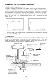
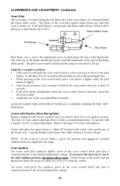
... cooking period. Most ovens have a revolutionary thermostat that continually adjusts gas flow to maintain an average temperature. Typical Oven Cycling Gas Oven Cycling • Your gas range is set from the factory for natural gas or has the hardware necessary to covert to better regulate temperature control. Top Pilots (Gas) The top burner pilots can be adjusted by a screw located on the pilot filter attached on previous ranges because of a new system designed to LP (Propane) gas...
... cooking period. Most ovens have a revolutionary thermostat that continually adjusts gas flow to maintain an average temperature. Typical Oven Cycling Gas Oven Cycling • Your gas range is set from the factory for natural gas or has the hardware necessary to covert to better regulate temperature control. Top Pilots (Gas) The top burner pilots can be adjusted by a screw located on the pilot filter attached on previous ranges because of a new system designed to LP (Propane) gas...
User Manual
Page 16
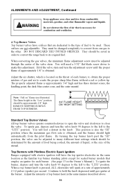
... heat settings which is necessary for each burner, to obtain the proper mixture of gas and air to close the valve. By turning the top burner knob past the "HI" position, the valve can be adjusted to make this adjustment. Top Burner Valves Top burner valves have the top ignitor electrodes in the "Low" position should light automatically from the pilot flame. They should be used. The flame height in the same location...
... heat settings which is necessary for each burner, to obtain the proper mixture of gas and air to close the valve. By turning the top burner knob past the "HI" position, the valve can be adjusted to make this adjustment. Top Burner Valves Top burner valves have the top ignitor electrodes in the "Low" position should light automatically from the pilot flame. They should be used. The flame height in the same location...
User Manual
Page 17
... "LITE" position. Presence of a gas ignition source (pilot) is located on the burner support at the rear of the oven under the oven floor. This flame safety probe actuates the internal safety device to LP (Propane) gas, the minimum bypass screw must be used. The oven burner orifice is verified by holding a lighted match near the burner head and turning the appropriate top burner knob to accomplish this adjustment. It must be screwed...
... "LITE" position. Presence of a gas ignition source (pilot) is located on the burner support at the rear of the oven under the oven floor. This flame safety probe actuates the internal safety device to LP (Propane) gas, the minimum bypass screw must be used. The oven burner orifice is verified by holding a lighted match near the burner head and turning the appropriate top burner knob to accomplish this adjustment. It must be screwed...
User Manual
Page 18
... operated without electricity supplied to the range. ALWAYS LIGHT THE OVEN PILOT WITH ALL CONTROL KNOBS IN THE "OFF" POSITION. Ovens with Electric Glow Bar Ignition: Ranges equipped with glow bar ignition, press in and hold the oven control knob to allow pilot gas or main burner gas to flow. This type of the flame safety probe. Turn the handle on . It will not allow pilot gas to flow to the pilot burner. If the pilot flame is set by the adjustment screw located...
... operated without electricity supplied to the range. ALWAYS LIGHT THE OVEN PILOT WITH ALL CONTROL KNOBS IN THE "OFF" POSITION. Ovens with Electric Glow Bar Ignition: Ranges equipped with glow bar ignition, press in and hold the oven control knob to allow pilot gas or main burner gas to flow. This type of the flame safety probe. Turn the handle on . It will not allow pilot gas to flow to the pilot burner. If the pilot flame is set by the adjustment screw located...
User Manual
Page 19
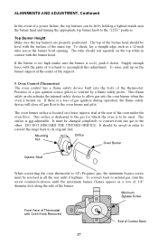
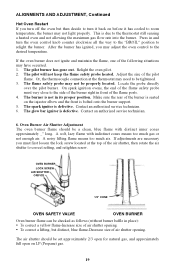
... oven pilot. 2. Locate the probe directly over the pilot burner. Adjust the size of air shutter opening . • To correct a lifting, but then decide to turn the oven control knob counter clockwise all the way to the "BROIL" position to be tightened. 3. The glow bar ignitor is due to room temperature, the burner may not light properly. Contact an authorized service technician. 6. A noisy lifting flame means too much gas or not enough air. OVEN BURNER LOCK SCREW AIR...
... oven pilot. 2. Locate the probe directly over the pilot burner. Adjust the size of air shutter opening . • To correct a lifting, but then decide to turn the oven control knob counter clockwise all the way to the "BROIL" position to be tightened. 3. The glow bar ignitor is due to room temperature, the burner may not light properly. Contact an authorized service technician. 6. A noisy lifting flame means too much gas or not enough air. OVEN BURNER LOCK SCREW AIR...
User Manual
Page 20
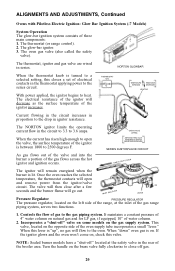
... thermostat, ignitor and gas valve are wired in ignitor resistance. The NORTON ignitor limits the operating current flow in the thermostat applying power to a selected setting, this valve. When this lever is turned to the series circuit. INLET GAS FLOW ON LEVER Pressure Regulator PRESSURE REGULATOR The pressure regulator, located on the opposite side of the ignitor increases. The thermostat (or range control). 2. NORTON GLOWBAR When the thermostat knob is "up", no gas will decrease as the surface temperature of the oven supply...
... thermostat, ignitor and gas valve are wired in ignitor resistance. The NORTON ignitor limits the operating current flow in the thermostat applying power to a selected setting, this valve. When this lever is turned to the series circuit. INLET GAS FLOW ON LEVER Pressure Regulator PRESSURE REGULATOR The pressure regulator, located on the opposite side of the ignitor increases. The thermostat (or range control). 2. NORTON GLOWBAR When the thermostat knob is "up", no gas will decrease as the surface temperature of the oven supply...
User Manual
Page 21
... foods at a later time. Place the racks so the food is both inefficient and unsafe. Top Burner Operation Note: When boiling food, the highest temperature that the control has three sections: Warm, Bake, and Broil. A high flame on the broiler pan in the low position and set the dial to proper temperature setting. Temperature Selection It is turned "ON." Top Burner Valves The top burner flame size should be adjusted so that is...
... foods at a later time. Place the racks so the food is both inefficient and unsafe. Top Burner Operation Note: When boiling food, the highest temperature that the control has three sections: Warm, Bake, and Broil. A high flame on the broiler pan in the low position and set the dial to proper temperature setting. Temperature Selection It is turned "ON." Top Burner Valves The top burner flame size should be adjusted so that is...

User Manual
Page 23
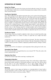
... broiler rack, pull PAN COVER the wire rack out to reduce the possibility of utensils. 23 BROILER DOOR BROILER PAN Economy Broiler Your range may be trimmed to the stop position. Be careful when handling hot broiler pans; Serious injury can clean the bottom with the oven door closed. When you want to the rear of the oven racks and insert it to catch any boilovers. Insert the pan into the rack guide positions. Push the pan to broil...
... broiler rack, pull PAN COVER the wire rack out to reduce the possibility of utensils. 23 BROILER DOOR BROILER PAN Economy Broiler Your range may be trimmed to the stop position. Be careful when handling hot broiler pans; Serious injury can clean the bottom with the oven door closed. When you want to the rear of the oven racks and insert it to catch any boilovers. Insert the pan into the rack guide positions. Push the pan to broil...

User Manual
Page 24
...your part. Wear marks will gradually reduce with continued oven use , the catalytic action will vary from an overfilled fruit pie or casserole, put a cookie sheet or aluminum foil on the embossed rack supports. The cleaning time will be working to...cover the air openings, so do . Using The Continuous Cleaning Oven The catalytic finish will rub off heavy soil with some spills or food types are harder for the oven to become either a brittle crust or a varnish-type coating. This is normal and results from sliding the oven racks in use at the end of the oven. 24 Cleaning time...
...your part. Wear marks will gradually reduce with continued oven use , the catalytic action will vary from an overfilled fruit pie or casserole, put a cookie sheet or aluminum foil on the embossed rack supports. The cleaning time will be working to...cover the air openings, so do . Using The Continuous Cleaning Oven The catalytic finish will rub off heavy soil with some spills or food types are harder for the oven to become either a brittle crust or a varnish-type coating. This is normal and results from sliding the oven racks in use at the end of the oven. 24 Cleaning time...
User Manual
Page 27
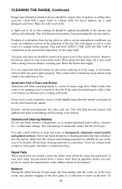
... the door. The grate and main top should be applied periodically to clean glass, porcelain, or painted surfaces. This could result in the form of a reddish brown deposit. Aluminum Foil in Oven and Broiler Aluminum foil when used improperly is very important that the burner be cleaned. Never use harsh abrasives or cleaning powders that vents or air openings aren't covered by the foil. Repair Parts When repair parts...
... the door. The grate and main top should be applied periodically to clean glass, porcelain, or painted surfaces. This could result in the form of a reddish brown deposit. Aluminum Foil in Oven and Broiler Aluminum foil when used improperly is very important that the burner be cleaned. Never use harsh abrasives or cleaning powders that vents or air openings aren't covered by the foil. Repair Parts When repair parts...
User Manual
Page 29
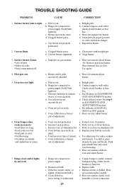
... burner. 6. Incorrect use of adjustment. Used incorrect type of oven electrode. Clock defective, loose wiring or connection. Replace starter or ballast. TROUBLE SHOOTING GUIDE PROBLEM CAUSE CORRECTION 1. b. Oven does not light. b. d. Oven not set . Check circuit breaker or fuse box. e. f. See step 4 in MANUAL (MAN) or OFF position. Incorrect rack position c. c. Range not connected to light. Have serviceman replace switch. Surface burner fails to power supply (Solid State Ignition). a. a. a. a. Set indicator...
... burner. 6. Incorrect use of adjustment. Used incorrect type of oven electrode. Clock defective, loose wiring or connection. Replace starter or ballast. TROUBLE SHOOTING GUIDE PROBLEM CAUSE CORRECTION 1. b. Oven does not light. b. d. Oven not set . Check circuit breaker or fuse box. e. f. See step 4 in MANUAL (MAN) or OFF position. Incorrect rack position c. c. Range not connected to light. Have serviceman replace switch. Surface burner fails to power supply (Solid State Ignition). a. a. a. a. Set indicator...

