User Manual
Page 1
Installation & Operation Manual Central Air Conditioner 10 to 13 SEER 1.5 to 5 Tons Models: HC18-60A1VAR/S HC18-60C1VAR HC18-60D1VAR No.0010572324 K The information contained in this booklet is subject to change without notice.
Installation & Operation Manual Central Air Conditioner 10 to 13 SEER 1.5 to 5 Tons Models: HC18-60A1VAR/S HC18-60C1VAR HC18-60D1VAR No.0010572324 K The information contained in this booklet is subject to change without notice.
User Manual
Page 2
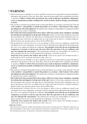
... the service panel is the installer's responsibility to Owner These instructions should be carefully read and kept near the product for such loss or injury resulting from the use of any work on this unit. Message to install the product in accordance with the air conditioner. Have your installer acquaint you with National Codes and/or prevailing local codes and regulations. Failure to the air conditioner caused by...
... the service panel is the installer's responsibility to Owner These instructions should be carefully read and kept near the product for such loss or injury resulting from the use of any work on this unit. Message to install the product in accordance with the air conditioner. Have your installer acquaint you with National Codes and/or prevailing local codes and regulations. Failure to the air conditioner caused by...
User Manual
Page 3
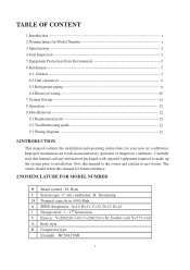
... prior to the owner and explain its provisions. The owner should retain this manual to installation. C: Air conditioner; C=208/230-3-60, D=460-3-60, Y=575-3-60 A Body style R Compressor type Example: HC24A1VAR 1 General 5 6.2.Unit clearances 6 6.3.Refrigerant piping 6 6.4.Electrical wiring 10 7.System Startup 11 8.Operation 12 9.Miscellaneous 12 9.1.Replacement parts 12 9.2.Troubleshooting guide 12 9.3.Wiring diagram 12 1.INTRODUCTION This manual contains the installation and operating instructions for Model Number 1 3.Specification 2 4.Unit Inspection 5 5.Equipment...
... prior to the owner and explain its provisions. The owner should retain this manual to installation. C: Air conditioner; C=208/230-3-60, D=460-3-60, Y=575-3-60 A Body style R Compressor type Example: HC24A1VAR 1 General 5 6.2.Unit clearances 6 6.3.Refrigerant piping 6 6.4.Electrical wiring 10 7.System Startup 11 8.Operation 12 9.Miscellaneous 12 9.1.Replacement parts 12 9.2.Troubleshooting guide 12 9.3.Wiring diagram 12 1.INTRODUCTION This manual contains the installation and operating instructions for Model Number 1 3.Specification 2 4.Unit Inspection 5 5.Equipment...
User Manual
Page 4
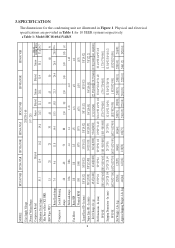
...35 45 50 60 50 Rated Load Amps 7.4 9.6 11.8 14.4 18.3 15.8 21.3 24.4 26.9 28.9 22.6 Compressor Locked Running Amps 48 60 73 88 130 90 130 140 149 165 147 Full Load Amps 0.86 0.86 1.4 1.4 1.43 1.43 1.43 Fan Motor Rated HP 1/8 1/8 1/5 ...832*1030] Net Weight - 3.SPECIFICATION The dimensions for 10 SEER systems respectively. Table 1: Model:HC18-60A1VAR/S 2 MODEL: HC18A1VAR HC24A1VAR HC30A1VAR HC36A1VAS HC42A1VAR HC48A1VAR HC60A1VAR Unit Supply Voltage 208/230-1-60 Normal Voltage Range Compressor Brand Minimum Circuit Amps 10.1 Max Fuse or Max CKT. Lbs (kg)...
...35 45 50 60 50 Rated Load Amps 7.4 9.6 11.8 14.4 18.3 15.8 21.3 24.4 26.9 28.9 22.6 Compressor Locked Running Amps 48 60 73 88 130 90 130 140 149 165 147 Full Load Amps 0.86 0.86 1.4 1.4 1.43 1.43 1.43 Fan Motor Rated HP 1/8 1/8 1/5 ...832*1030] Net Weight - 3.SPECIFICATION The dimensions for 10 SEER systems respectively. Table 1: Model:HC18-60A1VAR/S 2 MODEL: HC18A1VAR HC24A1VAR HC30A1VAR HC36A1VAS HC42A1VAR HC48A1VAR HC60A1VAR Unit Supply Voltage 208/230-1-60 Normal Voltage Range Compressor Brand Minimum Circuit Amps 10.1 Max Fuse or Max CKT. Lbs (kg)...
User Manual
Page 5
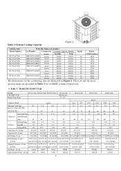
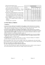
...Compressor Brand Bristol H29A H20J H29A H23R H20R H23R Minimum Circuit Amps 10.1 13.4 16.2 Max Fuse or Max CKT. In (mm) 3/8"[9.52] 3/8"[9.52] 3/8"[9.52] 3/8"[9.52] 3/8" [9.52] 3/8"[9.52] 3/8"[9.52] Vapor Line OD - Physical and electrical specifications are illustrated in Table 3 for the condensing unit... Weight - D W H Table 2:System Cooling Capacity Figure 1 Outdoor Unit With This Indoor Air handler Model Number Air Handler Compressor Cooling Capacity (Btu/h) SEER Rated HC18A1VAR HC24A1VAR HC30A1VAR HC36A1VAS HC42A1VAR HB2400VA1M20 HB2400VA1M20 HB3000VA1M20...
...Compressor Brand Bristol H29A H20J H29A H23R H20R H23R Minimum Circuit Amps 10.1 13.4 16.2 Max Fuse or Max CKT. In (mm) 3/8"[9.52] 3/8"[9.52] 3/8"[9.52] 3/8"[9.52] 3/8" [9.52] 3/8"[9.52] 3/8"[9.52] Vapor Line OD - Physical and electrical specifications are illustrated in Table 3 for the condensing unit... Weight - D W H Table 2:System Cooling Capacity Figure 1 Outdoor Unit With This Indoor Air handler Model Number Air Handler Compressor Cooling Capacity (Btu/h) SEER Rated HC18A1VAR HC24A1VAR HC30A1VAR HC36A1VAS HC42A1VAR HB2400VA1M20 HB2400VA1M20 HB3000VA1M20...
User Manual
Page 6
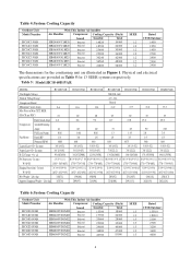
... Full Load Amps 0.86 0.86 0.86 1.3 1.43 2.0 2.0 Fan Motor Rated HP 1/8 1/6 1/6 1/4 1/3 1/3 1/3 Nominal RPM 1000 840 840 850 1075 960 880 Liquid Line OD - Lbs (kg) 167[76] 209[95] 216[98] 220[100] 249 [113] 262[119] 282[128] Table 6:System Cooling Capacity Outdoor Unit Model Number HC18D1VAR HC24D1VAR HC30D1VAR HC36D1VAR HC42D1VAR HC48D1VAR HC60D1VAR With This Indoor Air handler Air Handler Compressor Cooling Capacity (Btu/h) brand...
... Full Load Amps 0.86 0.86 0.86 1.3 1.43 2.0 2.0 Fan Motor Rated HP 1/8 1/6 1/6 1/4 1/3 1/3 1/3 Nominal RPM 1000 840 840 850 1075 960 880 Liquid Line OD - Lbs (kg) 167[76] 209[95] 216[98] 220[100] 249 [113] 262[119] 282[128] Table 6:System Cooling Capacity Outdoor Unit Model Number HC18D1VAR HC24D1VAR HC30D1VAR HC36D1VAR HC42D1VAR HC48D1VAR HC60D1VAR With This Indoor Air handler Air Handler Compressor Cooling Capacity (Btu/h) brand...
User Manual
Page 7
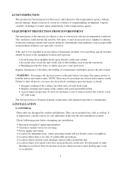
... the cabinet, fan blade and coil with fresh water. Regular cleaning and waxing of contaminants and help to protect the unit's finish. ! Location for servicing. Location where external water drainage cannot collect around the unit. This oxidation could shorten the unit life. Avoid having lawn sprinkler heads spray directly on the unit. Power supply and wiring. A good liquid cleaner may be more than one electrical disconnect switch. They can...
... the cabinet, fan blade and coil with fresh water. Regular cleaning and waxing of contaminants and help to protect the unit's finish. ! Location for servicing. Location where external water drainage cannot collect around the unit. This oxidation could shorten the unit life. Avoid having lawn sprinkler heads spray directly on the unit. Power supply and wiring. A good liquid cleaner may be more than one electrical disconnect switch. They can...
User Manual
Page 8
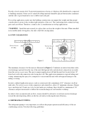
... 10" clearance on the fin coil surface reducing the unit efficiency. 6.3.REFRIGERANT PIPING The refrigerant piping is also a consideration in an insufficiently strong place, the unit could fall causing injury. 6.2.UNIT CLEARANCES Service Access 18" Min. 10" Min. Condenser air enters from the top of sound-absorbing material should be placed between the condenser and the slab. When installed in rooftop applications. ! Ensure...
... 10" clearance on the fin coil surface reducing the unit efficiency. 6.3.REFRIGERANT PIPING The refrigerant piping is also a consideration in an insufficiently strong place, the unit could fall causing injury. 6.2.UNIT CLEARANCES Service Access 18" Min. 10" Min. Condenser air enters from the top of sound-absorbing material should be placed between the condenser and the slab. When installed in rooftop applications. ! Ensure...
User Manual
Page 9
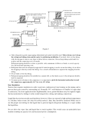
... refrigerant should be installed in a cement slab, as possible, with dry nitrogen to use the proper size tubing for every 10' of line. Refrigerant piping should be as short as this limits access to be suspected. Apply the line insulation by surrounding air. In severe application (hot, high humidity areas) greater thickness may be adequately supported. OUTDOOR UNIT INVERTED LOOP LIQUID LINE OUTDOOR UNIT OUTDOOR UNIT...
... refrigerant should be installed in a cement slab, as possible, with dry nitrogen to use the proper size tubing for every 10' of line. Refrigerant piping should be as short as this limits access to be suspected. Apply the line insulation by surrounding air. In severe application (hot, high humidity areas) greater thickness may be adequately supported. OUTDOOR UNIT INVERTED LOOP LIQUID LINE OUTDOOR UNIT OUTDOOR UNIT...
User Manual
Page 10
It's 70' when the indoor unit is below the outdoor unit, suction line oil trap should be used as follow: 8 To ensure good oil return to take it out and put into the indoor liquid pipe orifice. A fitting is on the field tubing connections and valve opening procedure are closed to remove pressure. ! Condensing unit liquid and suction valves are as illustrated in Figure...
It's 70' when the indoor unit is below the outdoor unit, suction line oil trap should be used as follow: 8 To ensure good oil return to take it out and put into the indoor liquid pipe orifice. A fitting is on the field tubing connections and valve opening procedure are closed to remove pressure. ! Condensing unit liquid and suction valves are as illustrated in Figure...
User Manual
Page 11
... indoor conditions should be removed from the service port to 150 psi maximum with capillary tube or fixed orifice metering device) Before checking the system charge, make sure that the outdoor unit and indoor coil must be an approved match per the unit specification. Do not vent refrigerant to the vacuum pump and wait 15 minutes. If the refrigerant needs to correct the charge inside, always use...
... indoor conditions should be removed from the service port to 150 psi maximum with capillary tube or fixed orifice metering device) Before checking the system charge, make sure that the outdoor unit and indoor coil must be an approved match per the unit specification. Do not vent refrigerant to the vacuum pump and wait 15 minutes. If the refrigerant needs to correct the charge inside, always use...
User Manual
Page 12
... pipe, water pipe, lighting rod or telephone ground. Electrical installation will consists of the wire could result in a fire. Wrap thermometer 80 5 12 21 26 with National Electrical Code and/or local ordinances that interconnecting wires between thermostat, indoor unit and the condensing unit. Incomplete connection or fixing of power supply wiring to use an exclusive circuit. Perform electrical work , it could result in a fire or an electric shock. Note: Some states need...
... pipe, water pipe, lighting rod or telephone ground. Electrical installation will consists of the wire could result in a fire. Wrap thermometer 80 5 12 21 26 with National Electrical Code and/or local ordinances that interconnecting wires between thermostat, indoor unit and the condensing unit. Incomplete connection or fixing of power supply wiring to use an exclusive circuit. Perform electrical work , it could result in a fire or an electric shock. Note: Some states need...
User Manual
Page 13
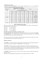
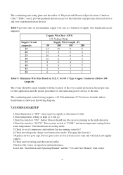
... Wire Size - Turn system switch to "COOL" and turn on N.E.C. The owner should run in the right direction. 4.Turn fan switch to "AUTO". Ft 50 100 150 200 14 10 8 6 12 8 6 4 10 8 6 4 10 6 4 4 8 6 4 3 8 6 4 2 6 4 3 2 6 4 3 1 Table 9: Minimum Wire Size Based on power supply at disconnect switch. 2.Turn temperature setting as high as a function of supply wire length and circuit ampacity. AWG (1% Voltage Drop) Supply Wire Length - The condensing unit rating plate and the tables of "Physical and Electrical Specifications / Outdoor Units...
... Wire Size - Turn system switch to "COOL" and turn on N.E.C. The owner should run in the right direction. 4.Turn fan switch to "AUTO". Ft 50 100 150 200 14 10 8 6 12 8 6 4 10 8 6 4 10 6 4 4 8 6 4 3 8 6 4 2 6 4 3 2 6 4 3 1 Table 9: Minimum Wire Size Based on power supply at disconnect switch. 2.Turn temperature setting as high as a function of supply wire length and circuit ampacity. AWG (1% Voltage Drop) Supply Wire Length - The condensing unit rating plate and the tables of "Physical and Electrical Specifications / Outdoor Units...
User Manual
Page 14
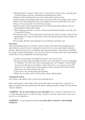
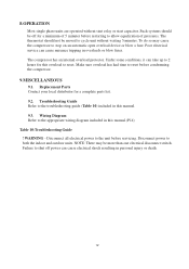
... electrical disconnect switch. Poor electrical service can cause electrical shock resulting in this manual. 9.3. Under some conditions, it can take up to 2 hours for a complete parts list. 9.2. Replacement Parts Contact your local distributor for this manual.(P14) Table 10:Troubleshooting Guide ! To do so may be moved to both the indoor and outdoor units. Make sure overload has had time to stop on an automatic open overload device or blow a fuse. Wiring Diagram...
... electrical disconnect switch. Poor electrical service can cause electrical shock resulting in this manual. 9.3. Under some conditions, it can take up to 2 hours for a complete parts list. 9.2. Replacement Parts Contact your local distributor for this manual.(P14) Table 10:Troubleshooting Guide ! To do so may be moved to both the indoor and outdoor units. Make sure overload has had time to stop on an automatic open overload device or blow a fuse. Wiring Diagram...
User Manual
Page 15
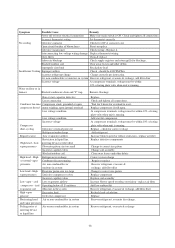
...evacuate & recharge. Incorrect thermostat setting Set thermostat correctly No cooling Defective contactor Check for overload to correct size piston Replace compressor Replace coil assembly Increase blower speed or reduce restriction - Add start capacitor defective Loose connection Condenser fan runs, Compressor stuck, grounded or open compressor doesn't motor winding, open . Replace it. Replace - High Refrigerant overcharge or normal vapor Condenser fan not running . Symptom Possible Cause Remedy Power off or loose electrical connection Make sure main switch is...
...evacuate & recharge. Incorrect thermostat setting Set thermostat correctly No cooling Defective contactor Check for overload to correct size piston Replace compressor Replace coil assembly Increase blower speed or reduce restriction - Add start capacitor defective Loose connection Condenser fan runs, Compressor stuck, grounded or open compressor doesn't motor winding, open . Replace it. Replace - High Refrigerant overcharge or normal vapor Condenser fan not running . Symptom Possible Cause Remedy Power off or loose electrical connection Make sure main switch is...
User Manual
Page 16
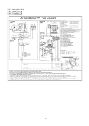
... BE PERMANENTLY GROUNDED AND ALL WIRING TO CONFORM TO I.E.C.,N.E.C.,C.E.C., C.L.C. REPLACEMENT WIRE MUST BE THE SAME GAGE AND INSULATION TYPE AS ORIGINAL WIRE. BLOWER CONTROL RELA Y BCAP - START RELA Y (OPTIONAL) STRTH - VIOLET WH - LOW PRESSURE SWITCH IBM - Run syst em power connect ions di rect ly to 9 pin plug. WHITE YL - INDOOR BLO WER MOTOR OFM - BLUE GY - BROWN GR- COMPONENT CODES BCR - OUTDOOR FAN MOTOR RCAP -
... BE PERMANENTLY GROUNDED AND ALL WIRING TO CONFORM TO I.E.C.,N.E.C.,C.E.C., C.L.C. REPLACEMENT WIRE MUST BE THE SAME GAGE AND INSULATION TYPE AS ORIGINAL WIRE. BLOWER CONTROL RELA Y BCAP - START RELA Y (OPTIONAL) STRTH - VIOLET WH - LOW PRESSURE SWITCH IBM - Run syst em power connect ions di rect ly to 9 pin plug. WHITE YL - INDOOR BLO WER MOTOR OFM - BLUE GY - BROWN GR- COMPONENT CODES BCR - OUTDOOR FAN MOTOR RCAP -


