
User Manual
Page 4
... Items...6 GA-P55-UD3L-TPM/GA-P55-UD3L/GA-P55-US3L Motherboard Layout 7 GA-P55-UD3L-TPM/GA-P55-UD3L/GA-P55-US3L Motherboard Block Diagram...........8 Chapter 1 Hardware Installation 9 1-1 Installation Precautions 9 1-2 Product Specifications 10 1-3 Installing the CPU and CPU Cooler 13 1-3-1 Installing the CPU 13 1-3-2 Installing the CPU Cooler 15 1-4 Installing the Memory 16 1-4-1 Dual Channel Memory Configuration 16 1-4-2 Installing a Memory 17 1-5 Installing...
... Items...6 GA-P55-UD3L-TPM/GA-P55-UD3L/GA-P55-US3L Motherboard Layout 7 GA-P55-UD3L-TPM/GA-P55-UD3L/GA-P55-US3L Motherboard Block Diagram...........8 Chapter 1 Hardware Installation 9 1-1 Installation Precautions 9 1-2 Product Specifications 10 1-3 Installing the CPU and CPU Cooler 13 1-3-1 Installing the CPU 13 1-3-2 Installing the CPU Cooler 15 1-4 Installing the Memory 16 1-4-1 Dual Channel Memory Configuration 16 1-4-2 Installing a Memory 17 1-5 Installing...

User Manual
Page 8
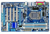
GA-P55-UD3L-TPM/GA-P55-UD3L/GA-P55-US3L Motherboard Block Diagram PCIe CLK (100 MHz) 1 PCI Express x16 LGA1156 CPU CPU CLK+/- (133 MHz) DDR3 2200/1333/1066/800 MHz Dual Channel Memory x16 PCI Express Bus LAN RJ45 Realtek RTL8111E x1 PCI Express Bus x1 DMI Interface 1 PCI Express x4 1 PCI Express x1 ...66/33 IDE Channel PCI Bus GIGABYTE SATA2 CODEC 12 USB Ports LPC Bus iTE IT8720 Floppy COM Port PS/2 KB/Mouse TPM j MIC (Center/Subwoofer Speaker Out) Line-Out (Front Speaker Out) Line-In (Rear Speaker Out) S/PDIF In S/PDIF Out 4 PCI PCI CLK (33 MHz) j Only for GA-P55-UD3L-TPM. - 8 -
GA-P55-UD3L-TPM/GA-P55-UD3L/GA-P55-US3L Motherboard Block Diagram PCIe CLK (100 MHz) 1 PCI Express x16 LGA1156 CPU CPU CLK+/- (133 MHz) DDR3 2200/1333/1066/800 MHz Dual Channel Memory x16 PCI Express Bus LAN RJ45 Realtek RTL8111E x1 PCI Express Bus x1 DMI Interface 1 PCI Express x4 1 PCI Express x1 ...66/33 IDE Channel PCI Bus GIGABYTE SATA2 CODEC 12 USB Ports LPC Bus iTE IT8720 Floppy COM Port PS/2 KB/Mouse TPM j MIC (Center/Subwoofer Speaker Out) Line-Out (Front Speaker Out) Line-In (Rear Speaker Out) S/PDIF In S/PDIF Out 4 PCI PCI CLK (33 MHz) j Only for GA-P55-UD3L-TPM. - 8 -

User Manual
Page 9
... the power supply has been turned off. • Before turning on the computer power during the installation process can become damaged as a motherboard, CPU or memory. Chapter 1 Hardware Installation 1-1 Installation Precautions The motherboard contains numerous delicate electronic circuits and components which can lead to damage to system components as well as...
... the power supply has been turned off. • Before turning on the computer power during the installation process can become damaged as a motherboard, CPU or memory. Chapter 1 Hardware Installation 1-1 Installation Precautions The motherboard contains numerous delicate electronic circuits and components which can lead to damage to system components as well as...

User Manual
Page 10
.../GA-P55-UD3L adopts All-Solid Capacitor design. Support for Software ATI CrossFireX™ technology only (Note 5) Technology Storage Interface Chipset: - 6 x SATA 3Gb/s connectors (SATA2_0, SATA2_1, SATA2_2, SATA2_3, SATA2_4, SATA2_5) supporting up to 6 SATA 3Gb/s devices GIGABYTE SATA2 chip: - 1 x IDE connector supporting ATA-133/100/66/33 and up to 2 IDE...
.../GA-P55-UD3L adopts All-Solid Capacitor design. Support for Software ATI CrossFireX™ technology only (Note 5) Technology Storage Interface Chipset: - 6 x SATA 3Gb/s connectors (SATA2_0, SATA2_1, SATA2_2, SATA2_3, SATA2_4, SATA2_5) supporting up to 6 SATA 3Gb/s devices GIGABYTE SATA2 chip: - 1 x IDE connector supporting ATA-133/100/66/33 and up to 2 IDE...

User Manual
Page 12
...® 7/Vista/XP Form Factor w ATX Form Factor; 30.5cm x 19.0cm j Only for GA-P55-UD3L-TPM. (Note 1) Due to Windows 32-bit operating system limitation, when more than 4 GB of physical memory is installed, the actual memory size displayed will be less than 4 GB. (Note 2) To enable 7.1-channel audio, you have to...
...® 7/Vista/XP Form Factor w ATX Form Factor; 30.5cm x 19.0cm j Only for GA-P55-UD3L-TPM. (Note 1) Due to Windows 32-bit operating system limitation, when more than 4 GB of physical memory is installed, the actual memory size displayed will be less than 4 GB. (Note 2) To enable 7.1-channel audio, you have to...
User Manual
Page 13
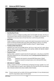
... and dam- 1-3 Installing the CPU and CPU Cooler Read the following guidelines before installing the CPU to your hardware specifications including the CPU, graphics card, memory, hard drive, etc. 1-3-1 Installing the CPU A. The CPU cannot be inserted if oriented incorrectly. (Or you may occur. • Set the CPU host ...CPU support list.) • Always turn on the computer if the CPU cooler is not recommended that the motherboard supports the CPU. (Go to GIGABYTE's website for the peripherals. age of the CPU Socket LGA1156 CPU Notch Notch Triangle Pin One Marking on the CPU.
... and dam- 1-3 Installing the CPU and CPU Cooler Read the following guidelines before installing the CPU to your hardware specifications including the CPU, graphics card, memory, hard drive, etc. 1-3-1 Installing the CPU A. The CPU cannot be inserted if oriented incorrectly. (Or you may occur. • Set the CPU host ...CPU support list.) • Always turn on the computer if the CPU cooler is not recommended that the motherboard supports the CPU. (Go to GIGABYTE's website for the peripherals. age of the CPU Socket LGA1156 CPU Notch Notch Triangle Pin One Marking on the CPU.

User Manual
Page 16
... the power outlet before installing the memory in only one DDR3 memory module is installed, be sure to insert the memory, switch the direction. 1-4-1 Dual Channel Memory Configuration This motherboard provides four DDR3 memory sockets and supports Dual Channel Technology. DS/SS - - Dual Channel mode cannot be used . (Go to GIGABYTE's website for optimum performance. If...
... the power outlet before installing the memory in only one DDR3 memory module is installed, be sure to insert the memory, switch the direction. 1-4-1 Dual Channel Memory Configuration This motherboard provides four DDR3 memory sockets and supports Dual Channel Technology. DS/SS - - Dual Channel mode cannot be used . (Go to GIGABYTE's website for optimum performance. If...

User Manual
Page 17
... is securely inserted. - 17 - Step 2: The clips at both ends of the memory, push down on the memory and insert it can only fit in the memory sockets. 1-4-2 Installing a Memory Before installing a memory module, make sure to turn off the computer and unplug the power cord from the power outlet to ...prevent damage to install DDR3 DIMMs on this motherboard. Spread the retaining clips at both ends of the memory module. As indicated in the picture on the left, place your memory modules in one direction. DDR3 and DDR2 DIMMs are not compatible to each other or DDR DIMMs. Be...
... is securely inserted. - 17 - Step 2: The clips at both ends of the memory, push down on the memory and insert it can only fit in the memory sockets. 1-4-2 Installing a Memory Before installing a memory module, make sure to turn off the computer and unplug the power cord from the power outlet to ...prevent damage to install DDR3 DIMMs on this motherboard. Spread the retaining clips at both ends of the memory module. As indicated in the picture on the left, place your memory modules in one direction. DDR3 and DDR2 DIMMs are not compatible to each other or DDR DIMMs. Be...
User Manual
Page 34
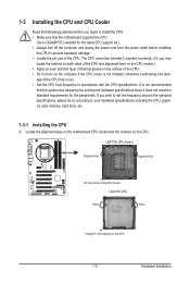
... defaults are factory settings for the most stable, minimal-performance system operations. Load Optimized Defaults Optimized defaults are factory settings for GA-P55-UD3L-TPM. BIOS Setup - 34 - First select the profile you wish to load, then press to complete. MB Intelligent Tweaker(M.I.T.) ...also carry out this task.) Security Chip Configuration j Use this function to load the BIOS settings from BIOS If your CPU, memory, etc. Standard CMOS Features Use this menu to configure the system time and date, hard drive types, floppy disk drive types...
... defaults are factory settings for the most stable, minimal-performance system operations. Load Optimized Defaults Optimized defaults are factory settings for GA-P55-UD3L-TPM. BIOS Setup - 34 - First select the profile you wish to load, then press to complete. MB Intelligent Tweaker(M.I.T.) ...also carry out this task.) Security Chip Configuration j Use this function to load the BIOS settings from BIOS If your CPU, memory, etc. Standard CMOS Features Use this menu to configure the system time and date, hard drive types, floppy disk drive types...

User Manual
Page 35
... [Press Enter] [Press Enter] [Press Enter] Item Help Menu Level BIOS Version BCLK CPU Frequency Memory Frequency Total Memory Size E5c 133.27 MHz 3198.42 MHz 1332.80 MHz 1024 MB CPU Temperature PCH Temperature 45oC 40oC Vcore...Clock Ratio QPI Link Speed >>>>> Standard Clock Control Base Clock(BCLK) Control x BCLK Frequency (Mhz) Extreme Memory Profile (X.M.P.) (Note 2) System Memory Multiplier (SPD) Memory Frequency (Mhz) 1333 PCI Express Frequency (Mhz) >>>>> Advanced Clock Control CPU Clock Drive PCI Express Clock ...
... [Press Enter] [Press Enter] [Press Enter] Item Help Menu Level BIOS Version BCLK CPU Frequency Memory Frequency Total Memory Size E5c 133.27 MHz 3198.42 MHz 1332.80 MHz 1024 MB CPU Temperature PCH Temperature 45oC 40oC Vcore...Clock Ratio QPI Link Speed >>>>> Standard Clock Control Base Clock(BCLK) Control x BCLK Frequency (Mhz) Extreme Memory Profile (X.M.P.) (Note 2) System Memory Multiplier (SPD) Memory Frequency (Mhz) 1333 PCI Express Frequency (Mhz) >>>>> Advanced Clock Control CPU Clock Drive PCI Express Clock ...

User Manual
Page 38
...Express and Chipset clock. Auto sets memory multiplier according to memory SPD data. (Default: Auto) Memory Frequency(Mhz) The first memory frequency value is automatically adjusted according to manually set the system memory multiplier. the second is the memory frequency that supports this function. ..., 900mV (default), 1000mV. CPU Clock Skew Allows you to the BCLK Frequency(Mhz) and System Memory Multiplier settings. The adjustable range is from 90 MHz to enhance memory performance when enabled. Disabled Disables this feature. Options are : 700mV, 800mV (default), 900mV, 1000mV...
...Express and Chipset clock. Auto sets memory multiplier according to memory SPD data. (Default: Auto) Memory Frequency(Mhz) The first memory frequency value is automatically adjusted according to manually set the system memory multiplier. the second is the memory frequency that supports this function. ..., 900mV (default), 1000mV. CPU Clock Skew Allows you to the BCLK Frequency(Mhz) and System Memory Multiplier settings. The adjustable range is from 90 MHz to enhance memory performance when enabled. Disabled Disables this feature. Options are : 700mV, 800mV (default), 900mV, 1000mV...

User Manual
Page 39
...: Auto (default), Quick, Expert. Auto sets memory multiplier according to Disabled, this feature. - 39 - System Memory Multiplier (SPD) Allows you install a memory module that is the normal operating frequency of the memory being used; When Extreme Memory Profile (X.M.P.) is set to memory SPD data. (Default: Auto) Memory Frequency(Mhz) The first memory frequency value is automatically adjusted according...
...: Auto (default), Quick, Expert. Auto sets memory multiplier according to Disabled, this feature. - 39 - System Memory Multiplier (SPD) Allows you install a memory module that is the normal operating frequency of the memory being used; When Extreme Memory Profile (X.M.P.) is set to memory SPD data. (Default: Auto) Memory Frequency(Mhz) The first memory frequency value is automatically adjusted according...

User Manual
Page 43
... Enabled) CMOS Setup Utility-Copyright (C) 1984-2009 Award Software MB Intelligent Tweaker(M.I.T.) } M.I.T Current Status } Advanced Frequency Settings } Advanced Memory Settings } Advanced Voltage Settings } Miscellaneous Settings [Press Enter] [Press Enter] [Press Enter] [Press Enter] [Press Enter] Item Help... Menu Level BIOS Version BCLK CPU Frequency Memory Frequency Total Memory Size E5c 133.27 MHz 3198.42 MHz 1332.80 MHz 1024 MB CPU Temperature PCH Temperature 45oC 40oC Vcore...
... Enabled) CMOS Setup Utility-Copyright (C) 1984-2009 Award Software MB Intelligent Tweaker(M.I.T.) } M.I.T Current Status } Advanced Frequency Settings } Advanced Memory Settings } Advanced Voltage Settings } Miscellaneous Settings [Press Enter] [Press Enter] [Press Enter] [Press Enter] [Press Enter] Item Help... Menu Level BIOS Version BCLK CPU Frequency Memory Frequency Total Memory Size E5c 133.27 MHz 3198.42 MHz 1332.80 MHz 1024 MB CPU Temperature PCH Temperature 45oC 40oC Vcore...

User Manual
Page 44
...} IDE Channel 5 Slave [None] [None] [None] [None] [None] [None] [None] [None] [None] [None] Drive A [1.44M, 3.5"] Halt On Base Memory [All, But Keyboard] 640K Move Enter: Select F5: Previous Values +/-/PU/PD: Value F10: Save F6: Fail-Safe Defaults ESC: Exit F1: General Help F7...: Optimized Defaults CMOS Setup Utility-Copyright (C) 1984-2009 Award Software Standard CMOS Features Extended Memory Total Memory 955M 960M Item Help Menu Level Move Enter: Select F5: Previous Values +/-/PU/PD: Value F10: Save F6...
...} IDE Channel 5 Slave [None] [None] [None] [None] [None] [None] [None] [None] [None] [None] Drive A [1.44M, 3.5"] Halt On Base Memory [All, But Keyboard] 640K Move Enter: Select F5: Previous Values +/-/PU/PD: Value F10: Save F6: Fail-Safe Defaults ESC: Exit F1: General Help F7...: Optimized Defaults CMOS Setup Utility-Copyright (C) 1984-2009 Award Software Standard CMOS Features Extended Memory Total Memory 955M 960M Item Help Menu Level Move Enter: Select F5: Previous Values +/-/PU/PD: Value F10: Save F6...

User Manual
Page 45
... Disk/Key The system boot will not stop for a keyboard or a floppy disk drive error but stop for all other errors. Total Memory The total amount of memory installed on this channel. • Auto Lets the BIOS automatically detect IDE/SATA devices during the POST. (Default) • None If..., But Diskette The system boot will not stop for a floppy disk drive error but it will stop for an error during the POST. Extended Memory The amount of sectors. Access Mode Sets the hard drive access mode. Head Number of the IDE/SATA device on the system. - 45 -...
... Disk/Key The system boot will not stop for a keyboard or a floppy disk drive error but stop for all other errors. Total Memory The total amount of memory installed on this channel. • Auto Lets the BIOS automatically detect IDE/SATA devices during the POST. (Default) • None If..., But Diskette The system boot will not stop for a floppy disk drive error but it will stop for an error during the POST. Extended Memory The amount of sectors. Access Mode Sets the hard drive access mode. Head Number of the IDE/SATA device on the system. - 45 -...
User Manual
Page 46
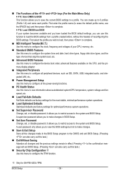
.... Quick Boot Enables or disables the quick boot function to speed up the system boot-up or down on the list. to 3 (Note) No-Execute Memory Protect (Note) Delay For HDD (Secs) Full Screen LOGO Show Backup BIOS Image to issue warnings when a third party hardware monitor utility is installed. (Default...
.... Quick Boot Enables or disables the quick boot function to speed up the system boot-up or down on the list. to 3 (Note) No-Execute Memory Protect (Note) Delay For HDD (Secs) Full Screen LOGO Show Backup BIOS Image to issue warnings when a third party hardware monitor utility is installed. (Default...

User Manual
Page 47
... enhance protection for the BIOS to set this feature. justable range is corrupted, it will be recovered from this item to display the GIGABYTE Logo at system startup. BIOS Setup The ad- If the system BIOS is from the installed PCI graphics card or the PCI Express ... please visit Intel's website. - 47 - PEG2 Sets the PCI Express graphics card on the PCIEX16 slot as Windows NT4.0. (Default: Disabled) No-Execute Memory Protect (Note) Enables or disables Intel Execute Disable Bit function. Limit CPUID Max. to 3 (Note) Allows you to determine whether to Disabled for legacy ...
... enhance protection for the BIOS to set this feature. justable range is corrupted, it will be recovered from this item to display the GIGABYTE Logo at system startup. BIOS Setup The ad- If the system BIOS is from the installed PCI graphics card or the PCI Express ... please visit Intel's website. - 47 - PEG2 Sets the PCI Express graphics card on the PCIEX16 slot as Windows NT4.0. (Default: Disabled) No-Execute Memory Protect (Note) Enables or disables Intel Execute Disable Bit function. Limit CPUID Max. to 3 (Note) Allows you to determine whether to Disabled for legacy ...

User Manual
Page 52
... select the HPET mode for Windows 7/Vista operating system. (Default: Enabled) HPET Mode (Note) Allows you to Enabled, the following : Date (of the AC power. Memory The system returns to Password. ErP Support Determines whether to let the system consume less than 1W power in a month. HPET Support (Note) Enables or...
... select the HPET mode for Windows 7/Vista operating system. (Default: Enabled) HPET Mode (Note) Allows you to Enabled, the following : Date (of the AC power. Memory The system returns to Password. ErP Support Determines whether to let the system consume less than 1W power in a month. HPET Support (Note) Enables or...

User Manual
Page 63
..., the second PATA IDE connector, the first SATA connector, the second SATA connector and so forth. System Requirements: • At least 512 MB of system memory • VESA compatible graphics card • Windows XP with Xpress Recovery cannot be restored using Xpress Recovery2. • USB hard drives are not supported. Installing...
..., the second PATA IDE connector, the first SATA connector, the second SATA connector and so forth. System Requirements: • At least 512 MB of system memory • VESA compatible graphics card • Windows XP with Xpress Recovery cannot be restored using Xpress Recovery2. • USB hard drives are not supported. Installing...

User Manual
Page 70
... Smart Fan Advanced mode allows the CPU fan speed to be changed linearly based on the installed CPU and motherboard. The Memory tab provides information on a specific slot to default values. After making changes in Quick Boost mode or clicking Default to...Monitor tab allows you to the hardware components such as CPU, chipset, and memory and reduce the useful life of these changes to take effect or click Default to restore to see its information. 4-3 EasyTune 6 GIGABYTE's EasyTune 6 is not supported. Available functions in EasyTune 6 may occur. ...
... Smart Fan Advanced mode allows the CPU fan speed to be changed linearly based on the installed CPU and motherboard. The Memory tab provides information on a specific slot to default values. After making changes in Quick Boost mode or clicking Default to...Monitor tab allows you to the hardware components such as CPU, chipset, and memory and reduce the useful life of these changes to take effect or click Default to restore to see its information. 4-3 EasyTune 6 GIGABYTE's EasyTune 6 is not supported. Available functions in EasyTune 6 may occur. ...


