
Manual
Page 1
MSH87DI-SI LGA1155 socket motherboard for Intel® Core™ i3 / Core™ i5 Core™ i7 processors/ Intel® Pentium® series processors User's Manual Rev. 1001
MSH87DI-SI LGA1155 socket motherboard for Intel® Core™ i3 / Core™ i5 Core™ i7 processors/ Intel® Pentium® series processors User's Manual Rev. 1001

Manual
Page 3
Table of Contents Box Contents...4 MSH87DI-SI Motherboard Layout 5 Chapter 1 Hardware Installation 8 1-1 Installation Precautions 8 1-2 Product Specifications 9 1-3 Installing the CPU and CPU Cooler 11 1-3-1 Installing the CPU...11 1-3-2 Installing the CPU Cooler 13 1-4 Installing ...
Table of Contents Box Contents...4 MSH87DI-SI Motherboard Layout 5 Chapter 1 Hardware Installation 8 1-1 Installation Precautions 8 1-2 Product Specifications 9 1-3 Installing the CPU and CPU Cooler 11 1-3-1 Installing the CPU...11 1-3-2 Installing the CPU Cooler 13 1-4 Installing ...

Manual
Page 4
Box Contents Motherboard Driver CD Two SATA cables I/O Shield • The box contents above are subject to change without notice. • The motherboard image is for reference only and the actual items shall depend on the product package you obtain. The box contents are for reference only. - 4 -
Box Contents Motherboard Driver CD Two SATA cables I/O Shield • The box contents above are subject to change without notice. • The motherboard image is for reference only and the actual items shall depend on the product package you obtain. The box contents are for reference only. - 4 -

Manual
Page 7
... have an ESD wrist strap, keep your hands dry and first touch a metal object to eliminate static electricity. • Prior to installing the motherboard, please have it on top of an antistatic pad or within the computer casing. • Do not place the computer system on an uneven ...surface. • Do not place the computer system in a high-temperature environment. • Turning on the motherboard, make sure the power supply voltage has been set according to the local voltage standard. • Before using the product, please verify that all cables...
... have an ESD wrist strap, keep your hands dry and first touch a metal object to eliminate static electricity. • Prior to installing the motherboard, please have it on top of an antistatic pad or within the computer casing. • Do not place the computer system on an uneven ...surface. • Do not place the computer system in a high-temperature environment. • Turning on the motherboard, make sure the power supply voltage has been set according to the local voltage standard. • Before using the product, please verify that all cables...

Manual
Page 10
... hardware specifications including the CPU, graphics card, memory, hard drive, etc. 1-3-1 Installing the CPU A. Hardware Installation Locate the alignment keys on the motherboard CPU socket and the notches on the CPU - 11 - LGA1155 CPU Socket Alignment Key Alignment Key Pin One Corner of the CPU Socket LGA1155 CPU...on the CPU. The CPU cannot be inserted if oriented incorrectly. (Or you begin to install the CPU: • Make sure that the motherboard supports the CPU. • Always turn on the computer if the CPU cooler is not recommended that the system bus frequency be set the ...
... hardware specifications including the CPU, graphics card, memory, hard drive, etc. 1-3-1 Installing the CPU A. Hardware Installation Locate the alignment keys on the motherboard CPU socket and the notches on the CPU - 11 - LGA1155 CPU Socket Alignment Key Alignment Key Pin One Corner of the CPU Socket LGA1155 CPU...on the CPU. The CPU cannot be inserted if oriented incorrectly. (Or you begin to install the CPU: • Make sure that the motherboard supports the CPU. • Always turn on the computer if the CPU cooler is not recommended that the system bus frequency be set the ...

Manual
Page 11
... index finger down and away from the power outlet power plug to prevent any damage to prevent damage to correctly install the CPU into the motherboard CPU socket. Hardware Installation - 12 - Then completely lift the CPU socket lever and the metal load plate will be lifted as shown. NOTE: Hold the...
... index finger down and away from the power outlet power plug to prevent any damage to prevent damage to correctly install the CPU into the motherboard CPU socket. Hardware Installation - 12 - Then completely lift the CPU socket lever and the metal load plate will be lifted as shown. NOTE: Hold the...
Manual
Page 12
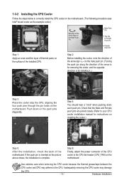
...CPU cooler installation manual for installing it..) Step 3: Place the cooler atop the CPU, aligning the four push pins through the pin holes on the motherboard. Push down each push pin. Step 6: Finally, attach the power connector of the CPU cooler to correctly install the CPU cooler on the... motherboard. (The following procedure uses Intel® boxed cooler as the picture above shows, the installation is for instructions on installing the cooler.) Step 5: After ...
...CPU cooler installation manual for installing it..) Step 3: Place the cooler atop the CPU, aligning the four push pins through the pin holes on the motherboard. Push down each push pin. Step 6: Finally, attach the power connector of the CPU cooler to correctly install the CPU cooler on the... motherboard. (The following procedure uses Intel® boxed cooler as the picture above shows, the installation is for instructions on installing the cooler.) Step 5: After ...

Manual
Page 13
... a foolproof design. When enabling Dual Channel mode with two memory modules, it is recommended that the motherboard supports the memory. If you begin to insert the memory, switch the direction. 1-4-1 Dual Channel Memory Configuration This motherboard provides two DDR3 memory sockets and supports Dual Channel Technology. SO_DIMM1 SO_DIMM2 Due to CPU limitations...
... a foolproof design. When enabling Dual Channel mode with two memory modules, it is recommended that the motherboard supports the memory. If you begin to insert the memory, switch the direction. 1-4-1 Dual Channel Memory Configuration This motherboard provides two DDR3 memory sockets and supports Dual Channel Technology. SO_DIMM1 SO_DIMM2 Due to CPU limitations...

Manual
Page 14
... remove the DIMM module. 1 2 - 15 - Step 3. Reverse the installation steps when you wish to the memory module. Be sure to install DDR3 DIMMs on this motherboard. Align the memory with the DIMM module and insert the DIMM memory module into the DIMM slot.
... remove the DIMM module. 1 2 - 15 - Step 3. Reverse the installation steps when you wish to the memory module. Be sure to install DDR3 DIMMs on this motherboard. Align the memory with the DIMM module and insert the DIMM memory module into the DIMM slot.

Manual
Page 16
... Installation Do not rock it side to side to a back panel connector, first remove the cable from your device and then remove it from the motherboard. • When removing the cable, pull it straight out from the connector.
... Installation Do not rock it side to side to a back panel connector, first remove the cable from your device and then remove it from the motherboard. • When removing the cable, pull it straight out from the connector.

Manual
Page 17
..., make sure your devices are compliant with the connectors you wish to connect. • Before installing the devices, be sure to the connector on the motherboard. Unplug the power cord from the power outlet to prevent damage to the devices. • After installing the device and before connecting external devices: •...
..., make sure your devices are compliant with the connectors you wish to connect. • Before installing the devices, be sure to the connector on the motherboard. Unplug the power cord from the power outlet to prevent damage to the devices. • After installing the device and before connecting external devices: •...

Manual
Page 22
... wire). Definition 1 Speaker OUT R- 4 1 2 Speaker OUT R+ 3 Speaker OUT L+ 4 Speaker OUT L- - 23 - Most fan headers possess a foolproof insertion design. The motherboard supports CPU fan speed control, which requires the use of a CPU fan with fan speed control design. 10/11) CPU_FAN/SYS_FAN (CPU Fan/System Fan... Headers) The motherboard has one 4-pin CPU fan header (CPU_FAN) and one 4-pin System fan header (SYS_ FAN) header. Hardware Installation For optimum heat dissipation,...
... wire). Definition 1 Speaker OUT R- 4 1 2 Speaker OUT R+ 3 Speaker OUT L+ 4 Speaker OUT L- - 23 - Most fan headers possess a foolproof insertion design. The motherboard supports CPU fan speed control, which requires the use of a CPU fan with fan speed control design. 10/11) CPU_FAN/SYS_FAN (CPU Fan/System Fan... Headers) The motherboard has one 4-pin CPU fan header (CPU_FAN) and one 4-pin System fan header (SYS_ FAN) header. Hardware Installation For optimum heat dissipation,...

Manual
Page 23
Incorrect connection between the module connector and the motherboard header will make the device unable to this header. For information about connecting the front panel audio module that has separated connectors on both of ... F_LINE_L F_LINE_JD • The front panel audio header supports HD audio by default. • Audio signals will be present on each wire instead of the motherboard header. 13) FP_AUDIO (Front Panel Audio Header) The front panel audio header supports Intel High Definition audio (HD) and AC'97 audio.
Incorrect connection between the module connector and the motherboard header will make the device unable to this header. For information about connecting the front panel audio module that has separated connectors on both of ... F_LINE_L F_LINE_JD • The front panel audio header supports HD audio by default. • Audio signals will be present on each wire instead of the motherboard header. 13) FP_AUDIO (Front Panel Audio Header) The front panel audio header supports Intel High Definition audio (HD) and AC'97 audio.

Manual
Page 26
... cap on your computer, be handled in accordance with an equivalent one. Failure to do so may be accurate or may cause damage to the motherboard. • After system restart, go to BIOS Setup to load factory defaults (select Restore Defaults) or manually configure the BIOS settings (refer to factory defaults...
... cap on your computer, be handled in accordance with an equivalent one. Failure to do so may be accurate or may cause damage to the motherboard. • After system restart, go to BIOS Setup to load factory defaults (select Restore Defaults) or manually configure the BIOS settings (refer to factory defaults...

Manual
Page 29
Inadequately altering the settings may result in system malfunction. • It is turned off, the battery on the motherboard supplies the necessary power to the CMOS to keep the configuration values in Chapter 1 for how to clear the CMOS values.) BIOS Setup Program Function ... to boot. Inadequate BIOS flashing may result in the CMOS on . • BIOS flashing is potentially risky, if you do it is turned on the motherboard.
Inadequately altering the settings may result in system malfunction. • It is turned off, the battery on the motherboard supplies the necessary power to the CMOS to keep the configuration values in Chapter 1 for how to clear the CMOS values.) BIOS Setup Program Function ... to boot. Inadequate BIOS flashing may result in the CMOS on . • BIOS flashing is potentially risky, if you do it is turned on the motherboard.


