Manual
Page 2
GS-R1161-RH Rack Mount Server Table of Content Safety, Care and Regulatory Information 4 Introduction 8 Contents Packages 8 Chapter 1 Features Summary 9 Chapter 2 System Hardware Installation 11 Step 2-1: Chassis Removal and Installation 11 Step 2-2: CPU Installation 12 Step 2-3: Heat Sink Installation 13 Step 2-4: Memory Installation 14 Step 2-5: PCI Expansion Card Installation 15 Step 2-6: Hard Disk Drive Installation 16 Step 2-7: FAN Duct Removal and Installation 17 Chapter 4 Motherboard Jumper Setting 18 4-1: GA-5YXS2-RH Motherboard Jumpper Setting 18 2
GS-R1161-RH Rack Mount Server Table of Content Safety, Care and Regulatory Information 4 Introduction 8 Contents Packages 8 Chapter 1 Features Summary 9 Chapter 2 System Hardware Installation 11 Step 2-1: Chassis Removal and Installation 11 Step 2-2: CPU Installation 12 Step 2-3: Heat Sink Installation 13 Step 2-4: Memory Installation 14 Step 2-5: PCI Expansion Card Installation 15 Step 2-6: Hard Disk Drive Installation 16 Step 2-7: FAN Duct Removal and Installation 17 Chapter 4 Motherboard Jumper Setting 18 4-1: GA-5YXS2-RH Motherboard Jumpper Setting 18 2
Manual
Page 4
... any kind into a grounding-type power outlet. Make sure you provide adequate space around the system for ventilation when you operate your system. GS-R1161-RH Rack Mount Server Safety, Care and Regulatory Information / Important safety information Read and follow all instructions marked on a laser device other than those specified in the product's documentation. * Only authorized service technicians should repair laser devices. / Precaution for Product...
... any kind into a grounding-type power outlet. Make sure you provide adequate space around the system for ventilation when you operate your system. GS-R1161-RH Rack Mount Server Safety, Care and Regulatory Information / Important safety information Read and follow all instructions marked on a laser device other than those specified in the product's documentation. * Only authorized service technicians should repair laser devices. / Precaution for Product...
Manual
Page 5
... No. 26 AWG or larger telecommunications line cord. * Do not plug a modem or telephone cable into the network interface controller (NIC) receptacle. * Disconnect the modem cable before opening a product enclosure, touching or installing internal components, or touching an uninsulated modem cable or jack. * Do not use a telephone line to report a gas leak while you will be notified as soon as possible...
... No. 26 AWG or larger telecommunications line cord. * Do not plug a modem or telephone cable into the network interface controller (NIC) receptacle. * Disconnect the modem cable before opening a product enclosure, touching or installing internal components, or touching an uninsulated modem cable or jack. * Do not use a telephone line to report a gas leak while you will be notified as soon as possible...
Manual
Page 6
... equipment. GS-R1161-RH Rack Mount Server Your telephone company may make such connections themselves, but should be connected to the user satisfaction. Users should not attempt to disconnect the equipment. The FCC prohibits this equipment, or equipment malfunctions, may be installed using an acceptable method of Industry Canada. The customer should contact the appropriate electric inspection authority, or electrician, as set out...
... equipment. GS-R1161-RH Rack Mount Server Your telephone company may make such connections themselves, but should be connected to the user satisfaction. Users should not attempt to disconnect the equipment. The FCC prohibits this equipment, or equipment malfunctions, may be installed using an acceptable method of Industry Canada. The customer should contact the appropriate electric inspection authority, or electrician, as set out...

Manual
Page 7
... European users only / CAUTION ™ Danger of used by the manufacturer. ™ Dispose of explosion if battery is incorrectly replaced. ™ Replace only with the same or equivalent type recommended by the device, to the manufacturer's instructions. 7 Safety Information NOTICE: The Load Number (LN) assigned to each terminal device denotes the percentage of the total load to be connected to a telephone...
... European users only / CAUTION ™ Danger of used by the manufacturer. ™ Dispose of explosion if battery is incorrectly replaced. ™ Replace only with the same or equivalent type recommended by the device, to the manufacturer's instructions. 7 Safety Information NOTICE: The Load Number (LN) assigned to each terminal device denotes the percentage of the total load to be connected to a telephone...
Manual
Page 8
... Handle Kit x 2 ; Power Supply (Installed) ; ; GS-R1161-RH Quick Refernece Guide ; Driver CD for motherboard driver & utility GA-5YXS2-RH Motherboard (Installed) FAN Duct x 1 Cables (RJ45) * The items listed above are subject to change without notice. 8 The guide provides instructions for configuration hardware for reference only, and are for the GS-R1161-RH your are not damaged during the shipping. This installation guide will assist you in installing similar hardware. CPU Heat Sink x 1 ; ; Using the following checklist to Gigabyte GS-R1161-RH Rack mount Server...
... Handle Kit x 2 ; Power Supply (Installed) ; ; GS-R1161-RH Quick Refernece Guide ; Driver CD for motherboard driver & utility GA-5YXS2-RH Motherboard (Installed) FAN Duct x 1 Cables (RJ45) * The items listed above are subject to change without notice. 8 The guide provides instructions for configuration hardware for reference only, and are for the GS-R1161-RH your are not damaged during the shipping. This installation guide will assist you in installing similar hardware. CPU Heat Sink x 1 ; ; Using the following checklist to Gigabyte GS-R1161-RH Rack mount Server...
Manual
Page 9
... y Support 256MB, 512MB, 1GB, and 2GB memory y Single-bit Errors Correction, Multiple Bit Errors Detection y 1 Riser card supports 1 PCI-E x8 and 1 PCI-E x8 (x1 bandwidth) add-on cards y 1 SO-DIMM add-on card y ICH9R y Supports LSI Software SW RAID 0/1/10 (Windows only) y 5 X System Fan y Intel® 82566DC & 82573VGbE controllers y XGI Volari Z9s y 32MB DDR2 y 4 x Hot-Swap SATA HDDs y ITE IT8718F Super I/O y 1 x Serial port (COM) y 4 x USB 2.0 dual-port connector (2 at front panel) y 1 x VGA connector y 2 x RJ45 LAN ports y P/S 2 Keyboard and Mouse Connectors y Phoenix BIOS on 8Mb flash ROM...
... y Support 256MB, 512MB, 1GB, and 2GB memory y Single-bit Errors Correction, Multiple Bit Errors Detection y 1 Riser card supports 1 PCI-E x8 and 1 PCI-E x8 (x1 bandwidth) add-on cards y 1 SO-DIMM add-on card y ICH9R y Supports LSI Software SW RAID 0/1/10 (Windows only) y 5 X System Fan y Intel® 82566DC & 82573VGbE controllers y XGI Volari Z9s y 32MB DDR2 y 4 x Hot-Swap SATA HDDs y ITE IT8718F Super I/O y 1 x Serial port (COM) y 4 x USB 2.0 dual-port connector (2 at front panel) y 1 x VGA connector y 2 x RJ45 LAN ports y P/S 2 Keyboard and Mouse Connectors y Phoenix BIOS on 8Mb flash ROM...
Manual
Page 10
GS-R1161-RH Rack Mount Server Server Management Functions: (Optional device) BMC Chip y H8S IPMI 2.0 controller Failure Detection y IPMI 2.0 specification of Server management Event Logging y 32KB Nonvolatile Memory to Log System Failure Events Remote Management y Follow the IPMI 2.0 specification of Server management Environment Ambient Temperature y Operating Temperature: 5oC to 40oC y Non-operating Temperature: 0oC to 50oC Relative Humidity y 10-80% operating Humidity at 30o C System Dimention: y 427.5mm x 567.5mm x 43.5 mm Electrical Power Supply y Single Power Supply ...
GS-R1161-RH Rack Mount Server Server Management Functions: (Optional device) BMC Chip y H8S IPMI 2.0 controller Failure Detection y IPMI 2.0 specification of Server management Event Logging y 32KB Nonvolatile Memory to Log System Failure Events Remote Management y Follow the IPMI 2.0 specification of Server management Environment Ambient Temperature y Operating Temperature: 5oC to 40oC y Non-operating Temperature: 0oC to 50oC Relative Humidity y 10-80% operating Humidity at 30o C System Dimention: y 427.5mm x 567.5mm x 43.5 mm Electrical Power Supply y Single Power Supply ...
Manual
Page 11
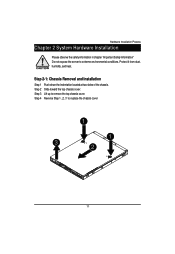
Step 3 Lift up to extreme environmental conditions. Step 2-1: Chassis Removal and Installation Step 1 Push down the indentation located at two sides of the chassis. Step 2 Slide toward the top chassis cover. Hardware Installation Process Chapter 2 System Hardware Installation Please observe the safety information in chapter "Important Safety Information" Do not expose the server to remove the top chassis cover. Protect it from dust, humidity, and heat. Step 4 Reverse Step 1, ,2, 3 to replace the chassis cover 1 1 3 2 11
Step 3 Lift up to extreme environmental conditions. Step 2-1: Chassis Removal and Installation Step 1 Push down the indentation located at two sides of the chassis. Step 2 Slide toward the top chassis cover. Hardware Installation Process Chapter 2 System Hardware Installation Please observe the safety information in chapter "Important Safety Information" Do not expose the server to remove the top chassis cover. Protect it from dust, humidity, and heat. Step 4 Reverse Step 1, ,2, 3 to replace the chassis cover 1 1 3 2 11
Manual
Page 12
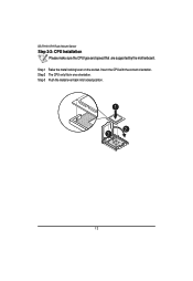
GS-R1161-RH Rack Mount Server Step 2-2: CPU Installation Please make sure the CPU type and speed that are supported by the motherboard. Insert the CPU with the correct orientation. Step 1 Raise the metal locking lever on the socket. Step 3 Push the metal lever back into locked position. 1 2 3 12 Step 2 The CPU only fits in one orientation.
GS-R1161-RH Rack Mount Server Step 2-2: CPU Installation Please make sure the CPU type and speed that are supported by the motherboard. Insert the CPU with the correct orientation. Step 1 Raise the metal locking lever on the socket. Step 3 Push the metal lever back into locked position. 1 2 3 12 Step 2 The CPU only fits in one orientation.

Manual
Page 13
Step 2 Seat the heat sink in the retention modules with the four screws. Installation completed. 2 2 2 2 1 13 Before putting the heat sink on the CPU, please well remember to apply the thermal conductivity compound on the CPU. Step 2-3: Heat Sink Installation Hardware Installation Process Step 1 Place the Heat Sink on the CPU.
Step 2 Seat the heat sink in the retention modules with the four screws. Installation completed. 2 2 2 2 1 13 Before putting the heat sink on the CPU, please well remember to apply the thermal conductivity compound on the CPU. Step 2-3: Heat Sink Installation Hardware Installation Process Step 1 Place the Heat Sink on the CPU.
Manual
Page 14
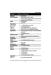
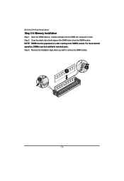
Step 2. For dual-channel operation, DIMMs must be installed in order starting from DIMM6 socket. Insert the DIMM memory module vertically into the DIMM slot, and push it down. GS-R1161-RH Rack Mount Server Step 2-4: Memory Installation Step 1. NOTE! DIMM must be populated in matched pairs. Reverse the installation steps when you wish to lock the DIMM module. Step 3. Close the plastic clip at both edges of the DIMM slots to remove the DIMM module. 2 1 2 14
Step 2. For dual-channel operation, DIMMs must be installed in order starting from DIMM6 socket. Insert the DIMM memory module vertically into the DIMM slot, and push it down. GS-R1161-RH Rack Mount Server Step 2-4: Memory Installation Step 1. NOTE! DIMM must be populated in matched pairs. Reverse the installation steps when you wish to lock the DIMM module. Step 3. Close the plastic clip at both edges of the DIMM slots to remove the DIMM module. 2 1 2 14
Manual
Page 15
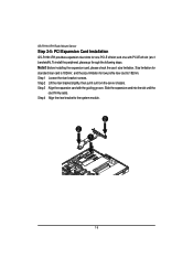
... riser card is 182mm; Step 3 Align the expansion card with PCI-E x8 slot (at x1 bandwidth). and one PCI-E x8 slot; Before installing the expansion card, please check the card size limitation. Step 1 Loosen the riser bracket screws. Size limitation for standard riser card is 182mm. Note!! To install the peripheral, please go through the following steps. GS-R1161-RH Rack Mount Server Step 2-5: PCI Expansion Card Installation GS-R1161-RH provides expansion riser slots for one with the guiding...
... riser card is 182mm; Step 3 Align the expansion card with PCI-E x8 slot (at x1 bandwidth). and one PCI-E x8 slot; Before installing the expansion card, please check the card size limitation. Step 1 Loosen the riser bracket screws. Size limitation for standard riser card is 182mm. Note!! To install the peripheral, please go through the following steps. GS-R1161-RH Rack Mount Server Step 2-5: PCI Expansion Card Installation GS-R1161-RH provides expansion riser slots for one with the guiding...
Manual
Page 16
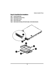
Step 5 Slide the blank into the bay until it with screws. Step 3 Slide hard disk into place. Hardware Installation Process Step 2-6: Hard Disk Drive Installation Step 1 Press the release button. Step 4 Secure it locks into blank. Step 2 Pull the blank out of the drive bay. Connect cable and power. 1 2 3 4 4 4 4 16
Step 5 Slide the blank into the bay until it with screws. Step 3 Slide hard disk into place. Hardware Installation Process Step 2-6: Hard Disk Drive Installation Step 1 Press the release button. Step 4 Secure it locks into blank. Step 2 Pull the blank out of the drive bay. Connect cable and power. 1 2 3 4 4 4 4 16
Manual
Page 17
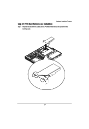
Guiding groove 17 Push down the fan duct into system ntil the its firmly seats. Hardware Installation Process Step 2-7: FAN Duct Removal and Installation Step 1 Align the fan duct with the guiding groove.
Guiding groove 17 Push down the fan duct into system ntil the its firmly seats. Hardware Installation Process Step 2-7: FAN Duct Removal and Installation Step 1 Align the fan duct with the guiding groove.
Manual
Page 18
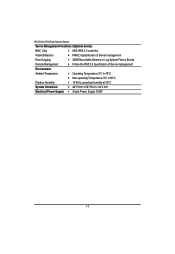
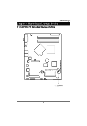
Motherboard Layout Chapter 4 Motherboard Jumper Setting 4-1: GA-5YXS2-RH Motherboard Jumpper Setting RECOVERY1 CLR_CMOS1 18
Motherboard Layout Chapter 4 Motherboard Jumper Setting 4-1: GA-5YXS2-RH Motherboard Jumpper Setting RECOVERY1 CLR_CMOS1 18
Manual
Page 19
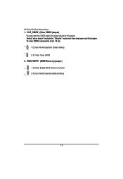
CLR_CMOS ( (Clear CMOS jumper) You may clear the CMOS data to prevent from improper use this jumper. RECOVERY1 (BIOS Revocery jumper) 1 1-2 Close: Enable BIOS Recovery function. 1 2-3 Close: Normal operation(Default setting) 19 Default value doesn't include the "Shunter" to its default values by this jumper. GS-R1161-RH Rack Mount Server 1. To clear CMOS, temporarily short 1-2 pin. 1 1-2 Close: Normal operation (Default setting) 1 2-3 Close: Clear CMOS 2.
CLR_CMOS ( (Clear CMOS jumper) You may clear the CMOS data to prevent from improper use this jumper. RECOVERY1 (BIOS Revocery jumper) 1 1-2 Close: Enable BIOS Recovery function. 1 2-3 Close: Normal operation(Default setting) 19 Default value doesn't include the "Shunter" to its default values by this jumper. GS-R1161-RH Rack Mount Server 1. To clear CMOS, temporarily short 1-2 pin. 1 1-2 Close: Normal operation (Default setting) 1 2-3 Close: Clear CMOS 2.