
User Manual
Page 2
Motherboard GA-Z97N-WIFI/GA-H97N-WIFI Nov. 3, 2014 Wireless Module Country Approvals: Motherboard GA-Z97N-WIFI GA-H97N-WIFI Nov. 3, 2014 See the latest safety and regulatory documents at GIGABYTE's website.
Motherboard GA-Z97N-WIFI/GA-H97N-WIFI Nov. 3, 2014 Wireless Module Country Approvals: Motherboard GA-Z97N-WIFI GA-H97N-WIFI Nov. 3, 2014 See the latest safety and regulatory documents at GIGABYTE's website.

User Manual
Page 3
Motherboard GA-H97N Nov. 3, 2014 Motherboard GA-H97N Nov. 3, 2014
Motherboard GA-H97N Nov. 3, 2014 Motherboard GA-H97N Nov. 3, 2014

User Manual
Page 4
... form or by any means without prior notice. All rights reserved. Check your motherboard looks like this product, GIGABYTE provides the following types of documentations: „„ For quick set-up of GIGABYTE. For example, "REV: 1.0" means the revision of this manual may be...: X.X." Changes to their respective owners. For product-related information, check on our website at: http://www.gigabyte.com Identifying Your Motherboard Revision The revision number on your motherboard revision before updating motherboard BIOS, drivers, or when looking for technical information.
... form or by any means without prior notice. All rights reserved. Check your motherboard looks like this product, GIGABYTE provides the following types of documentations: „„ For quick set-up of GIGABYTE. For example, "REV: 1.0" means the revision of this manual may be...: X.X." Changes to their respective owners. For product-related information, check on our website at: http://www.gigabyte.com Identifying Your Motherboard Revision The revision number on your motherboard revision before updating motherboard BIOS, drivers, or when looking for technical information.

User Manual
Page 5
Table of Contents Box Contents...6 Optional Items...6 GA-Z97N-WIFI/GA-H97N-WIFI/GA-H97N Motherboard Layout 7 GA-Z97N-WIFI/GA-H97N-WIFI/GA-H97N Motherboard Block Diagram 8 Chapter 1 Hardware Installation 9 1-1 Installation Precautions 9 1-2 Product Specifications 10 1-3 Installing the CPU and CPU Cooler 13 1-3-1 Installing the CPU...13 1-3-2 Installing the CPU Cooler ...
Table of Contents Box Contents...6 Optional Items...6 GA-Z97N-WIFI/GA-H97N-WIFI/GA-H97N Motherboard Layout 7 GA-Z97N-WIFI/GA-H97N-WIFI/GA-H97N Motherboard Block Diagram 8 Chapter 1 Hardware Installation 9 1-1 Installation Precautions 9 1-2 Product Specifications 10 1-3 Installing the CPU and CPU Cooler 13 1-3-1 Installing the CPU...13 1-3-2 Installing the CPU Cooler ...

User Manual
Page 6
.... 12CF1-3SATPW-4*R) …… 3.5" Front Panel with 2 USB 3.0/2.0 ports (Part No. 12CR1-FPX582-2*R) …… HDMI-to change without notice. Box Contents 55 GA-Z97N-WIFI, GA-H97N-WIFI, or GA-H97N motherboard 55 Motherboard driver disk 55 Wireless module driver diskjk 55 User's Manual 55 Quick Installation Guide 55 Two SATA cables 55 I/O Shield 55 One antennajk...
.... 12CF1-3SATPW-4*R) …… 3.5" Front Panel with 2 USB 3.0/2.0 ports (Part No. 12CR1-FPX582-2*R) …… HDMI-to change without notice. Box Contents 55 GA-Z97N-WIFI, GA-H97N-WIFI, or GA-H97N motherboard 55 Motherboard driver disk 55 Wireless module driver diskjk 55 User's Manual 55 Quick Installation Guide 55 Two SATA cables 55 I/O Shield 55 One antennajk...

User Manual
Page 8
NN Only for GA-Z97N-WIFI. GA-Z97N-WIFI/GA-H97N-WIFI/GA-H97N Motherboard Block Diagram PCI Express Bus x16 1 PCI Express x16 DVI-I LGA1150 CPU CPU CLK+/- (100 MHz) DDR3 1600/1333 MHz Dual Channel Memory PCIe CLK (...; GbE Realtek® LAN GbE LAN x1 x1 PCI Express Bus Intel® Z97 j Intel® H97 kl 6 SATA 6Gb/s 6 USB 3.0/2.0 4 USB 2.0/1.1 x1 Mini PCIe WiFi Modulejk CODEC LPC Bus iTE® Super I/O COM PS/2 KB/Mouse Rear Speaker Out Center/Subwoofer Speaker Out Side Speaker Out MIC Line Out Line...
NN Only for GA-Z97N-WIFI. GA-Z97N-WIFI/GA-H97N-WIFI/GA-H97N Motherboard Block Diagram PCI Express Bus x16 1 PCI Express x16 DVI-I LGA1150 CPU CPU CLK+/- (100 MHz) DDR3 1600/1333 MHz Dual Channel Memory PCIe CLK (...; GbE Realtek® LAN GbE LAN x1 x1 PCI Express Bus Intel® Z97 j Intel® H97 kl 6 SATA 6Gb/s 6 USB 3.0/2.0 4 USB 2.0/1.1 x1 Mini PCIe WiFi Modulejk CODEC LPC Bus iTE® Super I/O COM PS/2 KB/Mouse Rear Speaker Out Center/Subwoofer Speaker Out Side Speaker Out MIC Line Out Line...

User Manual
Page 9
...follow these procedures: •• Prior to the use of electrostatic discharge (ESD). Chapter 1 Hardware Installation 1-1 Installation Precautions The motherboard contains numerous delicate electronic circuits and components which can lead to damage to system components as well as physical harm to the user....verify that all cables and power connectors of your hardware components are connected tightly and securely. •• When handling the motherboard, avoid touching any installation steps or have a problem related to installation, make sure the chassis is best to wear an ...
...follow these procedures: •• Prior to the use of electrostatic discharge (ESD). Chapter 1 Hardware Installation 1-1 Installation Precautions The motherboard contains numerous delicate electronic circuits and components which can lead to damage to system components as well as physical harm to the user....verify that all cables and power connectors of your hardware components are connected tightly and securely. •• When handling the motherboard, avoid touching any installation steps or have a problem related to installation, make sure the chassis is best to wear an ...

User Manual
Page 12
... Viewer - Supported functions of each application may also differ depending on GIGABYTE's website to check the supported operating system(s) for the software listed in APP Center may differ by motherboard model. Fast Boot - Smart TimeLock - MM Only for GA-H97N. OO Only for GA-Z97N-WIFI. USB Blocker Support for Q-Flash Support for Smart Switch Support...
... Viewer - Supported functions of each application may also differ depending on GIGABYTE's website to check the supported operating system(s) for the software listed in APP Center may differ by motherboard model. Fast Boot - Smart TimeLock - MM Only for GA-H97N. OO Only for GA-Z97N-WIFI. USB Blocker Support for Q-Flash Support for Smart Switch Support...

User Manual
Page 13
...Or you may occur. •• Set the CPU host frequency in accordance with the CPU specifications. Locate the alignment keys on the motherboard CPU socket and the notches on the CPU - 13 - Hardware Installation The CPU cannot be set the frequency beyond hardware specifications since it... latest CPU support list.) •• Always turn on the computer if the CPU cooler is not recommended that the motherboard supports the CPU. (Go to GIGABYTE's website for the peripherals. It is not installed, otherwise overheating and damage of the CPU Socket LGA1150 CPU Notch Notch...
...Or you may occur. •• Set the CPU host frequency in accordance with the CPU specifications. Locate the alignment keys on the motherboard CPU socket and the notches on the CPU - 13 - Hardware Installation The CPU cannot be set the frequency beyond hardware specifications since it... latest CPU support list.) •• Always turn on the computer if the CPU cooler is not recommended that the motherboard supports the CPU. (Go to GIGABYTE's website for the peripherals. It is not installed, otherwise overheating and damage of the CPU Socket LGA1150 CPU Notch Notch...

User Manual
Page 14
... replacing the load plate, make sure to complete the installation of engaging the lever. Follow the steps below to correctly install the CPU into the motherboard CPU socket. •• Before installing the CPU, make sure the front end of the load plate is under its retention tab to turn off...
... replacing the load plate, make sure to complete the installation of engaging the lever. Follow the steps below to correctly install the CPU into the motherboard CPU socket. •• Before installing the CPU, make sure the front end of the load plate is under its retention tab to turn off...

User Manual
Page 15
... Follow the steps below to your CPU cooler installation manual for instructions on installing the cooler.) Step 5: After the installation, check the back of the motherboard. If the push pin is inserted as the example cooler.) Direction of the Arrow Sign on the Male Push Pin Male Push Pin The Top... each push pin. Hardware Installation Check that the Male and Female push pins are joined closely. (Refer to correctly install the CPU cooler on the motherboard. (The following procedure uses Intel® boxed cooler as the picture above shows, the installation is to remove the cooler, on the...
... Follow the steps below to your CPU cooler installation manual for instructions on installing the cooler.) Step 5: After the installation, check the back of the motherboard. If the push pin is inserted as the example cooler.) Direction of the Arrow Sign on the Male Push Pin Male Push Pin The Top... each push pin. Hardware Installation Check that the Male and Female push pins are joined closely. (Refer to correctly install the CPU cooler on the motherboard. (The following procedure uses Intel® boxed cooler as the picture above shows, the installation is to remove the cooler, on the...
User Manual
Page 16
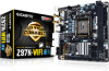
...memory, switch the direction. 1-4-1 Dual Channel Memory Configuration This motherboard provides two DDR3 memory sockets and supports Dual Channel Technology. Hardware Installation - 16 - A memory module can be used . (Go to GIGABYTE's website for optimum performance. When enabling Dual Channel mode with... two memory modules, it is recommended that the motherboard supports the memory. It is recommended that memory of the same capacity, brand...
...memory, switch the direction. 1-4-1 Dual Channel Memory Configuration This motherboard provides two DDR3 memory sockets and supports Dual Channel Technology. Hardware Installation - 16 - A memory module can be used . (Go to GIGABYTE's website for optimum performance. When enabling Dual Channel mode with... two memory modules, it is recommended that the motherboard supports the memory. It is recommended that memory of the same capacity, brand...

User Manual
Page 17
..., make sure to turn off the computer and unplug the power cord from the power outlet to prevent damage to install DDR3 DIMMs on this motherboard. Follow the steps below to correctly install your memory modules in the picture on the left, place your fingers on the socket. DDR3 and DDR2...
..., make sure to turn off the computer and unplug the power cord from the power outlet to prevent damage to install DDR3 DIMMs on this motherboard. Follow the steps below to correctly install your memory modules in the picture on the left, place your fingers on the socket. DDR3 and DDR2...

User Manual
Page 18
... guidelines before installing an expansion card to prevent hardware damage. Secure the card's metal bracket to install an expansion card: •• Make sure the motherboard supports the expansion card. After installing all expansion cards, replace the chassis cover(s). 6. Remove the metal slot cover from the power outlet before you begin...
... guidelines before installing an expansion card to prevent hardware damage. Secure the card's metal bracket to install an expansion card: •• Make sure the motherboard supports the expansion card. After installing all expansion cards, replace the chassis cover(s). 6. Remove the metal slot cover from the power outlet before you begin...

User Manual
Page 20
... be used to connect front speakers in a 4/5.1/7.1-channel audio configuration. Triple-Display Configurations for the Onboard Graphics: To set up a triple-display configuration, you install motherboard drivers in OS.
... be used to connect front speakers in a 4/5.1/7.1-channel audio configuration. Triple-Display Configurations for the Onboard Graphics: To set up a triple-display configuration, you install motherboard drivers in OS.

User Manual
Page 21
... retask other audio jack to be reconfigured to prevent an electrical short inside the cable connector. - 21 - Do not rock it straight out from the motherboard. •• When removing the cable, pull it side to side to perform different functions via the audio software (supported functions may vary based on...
... retask other audio jack to be reconfigured to prevent an electrical short inside the cable connector. - 21 - Do not rock it straight out from the motherboard. •• When removing the cable, pull it side to side to perform different functions via the audio software (supported functions may vary based on...

User Manual
Page 22
... sure your devices are compliant with the connectors you wish to connect. •• Before installing the devices, be sure to the connector on the motherboard.
... sure your devices are compliant with the connectors you wish to connect. •• Before installing the devices, be sure to the connector on the motherboard.

User Manual
Page 23
If the 12V power connector is turned off and all the components on the motherboard. 1/2) ATX_12V/ATX (2x2 12V Power Connector and 2x12 Main Power Connector) With the use of the power connector, the power supply can supply enough stable ...
If the 12V power connector is turned off and all the components on the motherboard. 1/2) ATX_12V/ATX (2x2 12V Power Connector and 2x12 Main Power Connector) With the use of the power connector, the power supply can supply enough stable ...
User Manual
Page 24
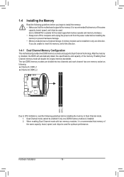
... of the positive side (+) and the negative side (-) of a fan with an equivalent one minute. 3. Hardware Installation - 24 - Do not place a jumper cap on this motherboard are not configuration jumper blocks. Danger of explosion if the battery is replaced with local environmental regulations. 3/4) CPU_FAN/SYS_FAN (Fan Headers) The fan headers on...
... of the positive side (+) and the negative side (-) of a fan with an equivalent one minute. 3. Hardware Installation - 24 - Do not place a jumper cap on this motherboard are not configuration jumper blocks. Danger of explosion if the battery is replaced with local environmental regulations. 3/4) CPU_FAN/SYS_FAN (Fan Headers) The fan headers on...
User Manual
Page 25
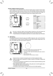
...front panel audio module to work or even damage it. Definition Pin No. Incorrect connection between the module connector and the motherboard header will be present on configuring a RAID array. Make sure the wire assignments of the module connector match the pin assignments of ...the motherboard header. DEBUG PORT DEBUG PORT DEBUG PORT DEBUG PORT DEBUG PORT DEBUG PORT 6) SATA3 0/1/2/3/4/5 (SATA 6Gb/s Connectors) The SATA connectors ...
...front panel audio module to work or even damage it. Definition Pin No. Incorrect connection between the module connector and the motherboard header will be present on configuring a RAID array. Make sure the wire assignments of the module connector match the pin assignments of ...the motherboard header. DEBUG PORT DEBUG PORT DEBUG PORT DEBUG PORT DEBUG PORT DEBUG PORT 6) SATA3 0/1/2/3/4/5 (SATA 6Gb/s Connectors) The SATA connectors ...


