User Guide
Page 5
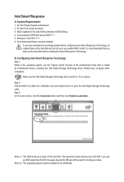
...utility. An Intel Core series processor 3. B. Make sure the Intel Rapid Storage Technology driver version is 64 GB. Step 3: On the main screen, click the Accelerate button and then click Enable acceleration. The maximum cache memory size is 11.0 or above. If you enable RAID mode. Intel...hard disk before configuring the Smart Response Technology, all original data on the hard disk will be used for the Intel SATA controllers in BIOS Setup 4. Configuring Intel Smart Response Technology Step 1: While in the notification area and double-click it to install all motherboard drivers, ...
...utility. An Intel Core series processor 3. B. Make sure the Intel Rapid Storage Technology driver version is 64 GB. Step 3: On the main screen, click the Accelerate button and then click Enable acceleration. The maximum cache memory size is 11.0 or above. If you enable RAID mode. Intel...hard disk before configuring the Smart Response Technology, all original data on the hard disk will be used for the Intel SATA controllers in BIOS Setup 4. Configuring Intel Smart Response Technology Step 1: While in the notification area and double-click it to install all motherboard drivers, ...
Manual
Page 4
Table of Contents Box Contents...6 Optional Items...6 GA-Z77X-UD5H Motherboard Layout 7 GA-Z77X-UD5H Motherboard Block Diagram 8 Chapter 1 Hardware Installation 9 1-1 Installation Precautions 9 1-2 Product Specifications 10 1-3 Installing the CPU and CPU Cooler 13 1-3-1... SLI Configuration 19 1-7 Back Panel Connectors 20 1-8 Onboard Buttons, Switches and LEDs 23 1-9 Internal Connectors 25 Chapter 2 BIOS Setup 37 2-1 Startup Screen 38 2-2 The Main Menu 39 2-3 M.I.T...41 2-4 System...52 2-5 BIOS Features 53 2-6 Peripherals...55 2-7 Power Management 60 2-8 Save & Exit...62 - 4 -
Table of Contents Box Contents...6 Optional Items...6 GA-Z77X-UD5H Motherboard Layout 7 GA-Z77X-UD5H Motherboard Block Diagram 8 Chapter 1 Hardware Installation 9 1-1 Installation Precautions 9 1-2 Product Specifications 10 1-3 Installing the CPU and CPU Cooler 13 1-3-1... SLI Configuration 19 1-7 Back Panel Connectors 20 1-8 Onboard Buttons, Switches and LEDs 23 1-9 Internal Connectors 25 Chapter 2 BIOS Setup 37 2-1 Startup Screen 38 2-2 The Main Menu 39 2-3 M.I.T...41 2-4 System...52 2-5 BIOS Features 53 2-6 Peripherals...55 2-7 Power Management 60 2-8 Save & Exit...62 - 4 -

Manual
Page 38
BIOS Setup - 38 - 2-1 Startup Screen The following startup Logo screen will boot from the device immediately. Function Keys Function Keys: : BIOS SETUP\Q-FLASH Press the key to enter BIOS Setup or to access the Q-Flash utility in Boot Menu is effective for one time only. In Boot Menu, use the up... select the first boot device, then press to set the first boot device without having to enter BIOS Setup first. The system will appear when the computer boots. Note: The setting in BIOS Setup. : SYSTEM INFORMATION Press the key to display your system information. : BOOT MENU Boot Menu...
BIOS Setup - 38 - 2-1 Startup Screen The following startup Logo screen will boot from the device immediately. Function Keys Function Keys: : BIOS SETUP\Q-FLASH Press the key to enter BIOS Setup or to access the Q-Flash utility in Boot Menu is effective for one time only. In Boot Menu, use the up... select the first boot device, then press to set the first boot device without having to enter BIOS Setup first. The system will appear when the computer boots. Note: The setting in BIOS Setup. : SYSTEM INFORMATION Press the key to display your system information. : BOOT MENU Boot Menu...

Manual
Page 39
The 3D BIOS Screen (Default) On GIGABYTE's uniquely designed 3D BIOS screen, you want. (Sample BIOS Version: F1q) Switch to accept or enter a sub-menu. For example, pass your mouse to move among the items and press to 3D BIOS screen Setup Menus Enter Q-Flash Select Default Language Help Function Keys Configuration Items Current ...function menu icons at the bottom of the screen or press to switch to the main menu of the BIOS Setup program. (If a mouse is not connected, the 3D BIOS screen will automatically switch to the main menu of the BIOS Setup program, press arrow keys to move...
The 3D BIOS Screen (Default) On GIGABYTE's uniquely designed 3D BIOS screen, you want. (Sample BIOS Version: F1q) Switch to accept or enter a sub-menu. For example, pass your mouse to move among the items and press to 3D BIOS screen Setup Menus Enter Q-Flash Select Default Language Help Function Keys Configuration Items Current ...function menu icons at the bottom of the screen or press to switch to the main menu of the BIOS Setup program. (If a mouse is not connected, the 3D BIOS screen will automatically switch to the main menu of the BIOS Setup program, press arrow keys to move...

Manual
Page 40
... enter a menu / Increase the numeric value or make changes / Decrease the numeric value or make changes Switch to 3D BIOS screen Restore the previous BIOS settings for the current submenus Load the Optimized BIOS default settings for the current submenus Access the Q-Flash utility Display system information Save all the changes made in this...
... enter a menu / Increase the numeric value or make changes / Decrease the numeric value or make changes Switch to 3D BIOS screen Restore the previous BIOS settings for the current submenus Load the Optimized BIOS default settings for the current submenus Access the Q-Flash utility Display system information Save all the changes made in this...

Manual
Page 42
...adjustable range is from 400 MHz to 3200 MHz. (Default: Auto) && CPU Clock Ratio Allows you to set the onboard graphics clock. BIOS Setup - 42 - `` M.I.T. The adjustable range is highly recommended that the CPU frequency be set the CPU base clock and PCIe bus ... (Default: Auto) Important: It is dependent on the CPU being installed. && CPU Frequency Displays the current operating CPU frequency. Current Status This screen provides information on CPU/memory frequencies/parameters. `` Advanced Frequency Settings && CPU/PCIe Base Clock Allows you to alter the clock ratio for the installed ...
...adjustable range is from 400 MHz to 3200 MHz. (Default: Auto) && CPU Clock Ratio Allows you to set the onboard graphics clock. BIOS Setup - 42 - `` M.I.T. The adjustable range is highly recommended that the CPU frequency be set the CPU base clock and PCIe bus ... (Default: Auto) Important: It is dependent on the CPU being installed. && CPU Frequency Displays the current operating CPU frequency. Current Status This screen provides information on CPU/memory frequencies/parameters. `` Advanced Frequency Settings && CPU/PCIe Base Clock Allows you to alter the clock ratio for the installed ...

Manual
Page 46
The respective timing setting screens are configurable only when DRAM Timing Selectable is set to default values by loading optimized defaults or clearing the CMOS values. `` Advanced Voltage Settings BIOS Setup - 46 - If this occurs, please reset the board to Quick or Expert. Note: Your system may become unstable or fail to boot after you make changes on the memory timings. `` Channel A/B Timing Settings This sub-menu provides memory timing settings for each channel of memory.
The respective timing setting screens are configurable only when DRAM Timing Selectable is set to default values by loading optimized defaults or clearing the CMOS values. `` Advanced Voltage Settings BIOS Setup - 46 - If this occurs, please reset the board to Quick or Expert. Note: Your system may become unstable or fail to boot after you make changes on the memory timings. `` Channel A/B Timing Settings This sub-menu provides memory timing settings for each channel of memory.

Manual
Page 53
...this type is installed. && Bootup NumLock State Enables or disables Numlock feature on this item to display the GIGABYTE Logo at least one device for a specific type. Disabled skips the GIGABYTE Logo when the system starts up. (Default: Enabled) && PCI ROM Priority Allows you can set hard ...device list. Removable storage devices that presents the devices of the keyboard after the POST. (Default: Enabled) && Full Screen LOGO Show Allows you want to launch. BIOS Setup Or if you to determine whether to enter the submenu that support GPT format will be prefixed with "UEFI:" ...
...this type is installed. && Bootup NumLock State Enables or disables Numlock feature on this item to display the GIGABYTE Logo at least one device for a specific type. Disabled skips the GIGABYTE Logo when the system starts up. (Default: Enabled) && PCI ROM Priority Allows you can set hard ...device list. Removable storage devices that presents the devices of the keyboard after the POST. (Default: Enabled) && Full Screen LOGO Show Allows you want to launch. BIOS Setup Or if you to determine whether to enter the submenu that support GPT format will be prefixed with "UEFI:" ...

Manual
Page 71
... begin the BIOS update. Step 1: 1. Q-Flash Utility v1.02 Model Name : Z77X-UD5H BIOS Version : F1q BIOS Date : 02/11/2012 Flash Type/Size : MXIC 25L6465E/6406E 8MB Update BIOS From Drive Flash Disk SSaveleecBtIDOeSvtioceDrive Return to update BIOS?" Q-Flash BIOS update is saved. Unique Features Updating the BIOS In the ...flash drive or hard drive when the system is displayed on the screen. In the main menu of the system reading the BIOS file from the USB flash drive is updating the BIOS. Make sure the BIOS update file matches your motherboard model. B. appears, select Yes to...
... begin the BIOS update. Step 1: 1. Q-Flash Utility v1.02 Model Name : Z77X-UD5H BIOS Version : F1q BIOS Date : 02/11/2012 Flash Type/Size : MXIC 25L6465E/6406E 8MB Update BIOS From Drive Flash Disk SSaveleecBtIDOeSvtioceDrive Return to update BIOS?" Q-Flash BIOS update is saved. Unique Features Updating the BIOS In the ...flash drive or hard drive when the system is displayed on the screen. In the main menu of the system reading the BIOS file from the USB flash drive is updating the BIOS. Make sure the BIOS update file matches your motherboard model. B. appears, select Yes to...

Manual
Page 72
System will re-detect all peripheral devices after the system restarts. Select Yes to CMOS and exit BIOS Setup. And then select Yes to save settings to load BIOS defaults Step 5: Select Save & Exit Setup and press . Unique Features - 72 - Select Load Optimized Defaults on the Save & Exit screen and press to enter BIOS Setup. Step 4: During the POST, press to load BIOS defaults. The procedure is complete after a BIOS update, so we recommend that you reload BIOS defaults.
System will re-detect all peripheral devices after the system restarts. Select Yes to CMOS and exit BIOS Setup. And then select Yes to save settings to load BIOS defaults Step 5: Select Save & Exit Setup and press . Unique Features - 72 - Select Load Optimized Defaults on the Save & Exit screen and press to enter BIOS Setup. Step 4: During the POST, press to load BIOS defaults. The procedure is complete after a BIOS update, so we recommend that you reload BIOS defaults.

Manual
Page 73
... Begin 1. B. Follow the on -screen instructions to boot. - 73 - Load BIOS Defaults after BIOS Update: Select the Load CMOS default after BIOS update check box and then the system will automatically load BIOS defaults after BIOS update and after updating the BIOS. Follow the on -screen instructions to save the BIOS update file obtained from GIGABYTE's website and follow the...
... Begin 1. B. Follow the on -screen instructions to boot. - 73 - Load BIOS Defaults after BIOS Update: Select the Load CMOS default after BIOS update check box and then the system will automatically load BIOS defaults after BIOS update and after updating the BIOS. Follow the on -screen instructions to save the BIOS update file obtained from GIGABYTE's website and follow the...
Manual
Page 76
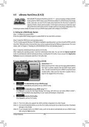
...) Step 3: Install the motherboard drivers and the X.H.D utiltiy After installing the operating system, insert the motherboard driver disk. Using GIGABYTE eXtreme Hard Drive (X.H.D) Instructions (Note 2): Before launching X.H.D, make sure the newly added harddrive has equal or greater capacity than ... the system BIOS Setup program to enhance your hard drive read/ write performance without the need for complex and time-consuming configurations. You can go to the Application Software screen to individually install the X.H.D utility later. A. B. To manually set up a RAID 0 array. 2. ...
...) Step 3: Install the motherboard drivers and the X.H.D utiltiy After installing the operating system, insert the motherboard driver disk. Using GIGABYTE eXtreme Hard Drive (X.H.D) Instructions (Note 2): Before launching X.H.D, make sure the newly added harddrive has equal or greater capacity than ... the system BIOS Setup program to enhance your hard drive read/ write performance without the need for complex and time-consuming configurations. You can go to the Application Software screen to individually install the X.H.D utility later. A. B. To manually set up a RAID 0 array. 2. ...

Manual
Page 82
... the hard disk before configuring the Smart Response Technology, all motherboard drivers, including the Intel Rapid Storage Technology driver. Step 2: Find the IRST icon in BIOS Setup 4. System Requirements 1. RAID enabled for storing your computer when completed. Windows 7 with SP1 (Note 2) 6. j k (Note 1) The SSD works as a cache of the... the Intel Rapid Storage Technology utility. Unique Features - 82 - An Intel Chipset-based motherboard 2. An Intel Core series processor 3. Step 3: On the main screen, click the Accelerate button and then click Enable acceleration.
... the hard disk before configuring the Smart Response Technology, all motherboard drivers, including the Intel Rapid Storage Technology driver. Step 2: Find the IRST icon in BIOS Setup 4. System Requirements 1. RAID enabled for storing your computer when completed. Windows 7 with SP1 (Note 2) 6. j k (Note 1) The SSD works as a cache of the... the Intel Rapid Storage Technology utility. Unique Features - 82 - An Intel Chipset-based motherboard 2. An Intel Core series processor 3. Step 3: On the main screen, click the Accelerate button and then click Enable acceleration.

Manual
Page 87
C. Create RAID Volume If you press + , the MAIN MENU screen will appear (Figure 3). Option ROM - 11.0.0.1339 Copyright(C) 2003-11 Intel Corporation. Reset Disks to enter the RAID Configuration Utility. Recovery Volume Options 5. Acceleration Options 6. ... ROM - 11.0.0.1339 Copyright(C) 2003-11 Intel Corporation. Figure 2 Step 2: After you want to create a RAID array, select Create RAID Volume in RAID BIOS Enter the RAID BIOS setup utility to configure a RAID array. Skip this step and proceed with the installation of Windows operating system for a message which says "Press to...
C. Create RAID Volume If you press + , the MAIN MENU screen will appear (Figure 3). Option ROM - 11.0.0.1339 Copyright(C) 2003-11 Intel Corporation. Reset Disks to enter the RAID Configuration Utility. Recovery Volume Options 5. Acceleration Options 6. ... ROM - 11.0.0.1339 Copyright(C) 2003-11 Intel Corporation. Figure 2 Step 2: After you want to create a RAID array, select Create RAID Volume in RAID BIOS Enter the RAID BIOS setup utility to configure a RAID array. Skip this step and proceed with the installation of Windows operating system for a message which says "Press to...

Manual
Page 95
... Config menu appears (Figure 5). Marvell BIOS Setup (c) 2009 Marvell Technology Group Ltd. [ Adapter] [ Devices] [ RAID ] RAID Config Create VD Delete VD Wipe out disk Spare Management ENTER/SPACE: Select, ESC: Back/Exit Figure 5 - 95 - On the main screen of the RAID setup utility (Figure ...4), use the left or right arrow key to move through tabs. Marvell BIOS Setup (c) 2009 Marvell Technology Group Ltd. [ Adapter ] [ Devices ] [ RAID ] Adapter ...
... Config menu appears (Figure 5). Marvell BIOS Setup (c) 2009 Marvell Technology Group Ltd. [ Adapter] [ Devices] [ RAID ] RAID Config Create VD Delete VD Wipe out disk Spare Management ENTER/SPACE: Select, ESC: Back/Exit Figure 5 - 95 - On the main screen of the RAID setup utility (Figure ...4), use the left or right arrow key to move through tabs. Marvell BIOS Setup (c) 2009 Marvell Technology Group Ltd. [ Adapter ] [ Devices ] [ RAID ] Adapter ...

Manual
Page 96
... whether to quickly erase old data on NEXT. VD Name: Enter an array name with an asterisk (Figure 6). Marvell BIOS Setup (c) 2009 Marvell Technology Group Ltd. [ Adapter] [ Devices] [ RAID ] Select free disks to create Port Disk...display options. RAID Level: Select a RAID level. Cache Mode: Select write-back or write-through cache. 5. Marvell BIOS Setup (c) 2009 Marvell Technology Group Ltd. [ Adapter] [ Devices] [ RAID ] Select free disks to add ...Back/Exit Appendix Figure 7 - 96 - Step 2: The next screen displays the two hard drives you installed. Sequence: 1.
... whether to quickly erase old data on NEXT. VD Name: Enter an array name with an asterisk (Figure 6). Marvell BIOS Setup (c) 2009 Marvell Technology Group Ltd. [ Adapter] [ Devices] [ RAID ] Select free disks to create Port Disk...display options. RAID Level: Select a RAID level. Cache Mode: Select write-back or write-through cache. 5. Marvell BIOS Setup (c) 2009 Marvell Technology Group Ltd. [ Adapter] [ Devices] [ RAID ] Select free disks to add ...Back/Exit Appendix Figure 7 - 96 - Step 2: The next screen displays the two hard drives you installed. Sequence: 1.

Manual
Page 97
... Speed Status SATA 3Gb/s FREE SATA 3Gb/s FREE Create the VD?[Y] Figure 8 When completed, the RAID tab will display the new array. (Figure 9) Marvell BIOS Setup (c) 2009 Marvell Technology Group Ltd. [ Adapter ] [ Devices ] [ RAID ] [Virtual Disks] ID Name Size Level 0 GBT 152.4GB RAID0 [... Speed Status SATA 3Gb/s ASSIGNED SATA 3Gb/s ASSIGNED ENTER/SPACE: Select, ESC: Back/Exit Figure 9 To exit the RAID BIOS utility, press on the main screen and press to cancel (Figure 8). Appendix Now, you can proceed to begin creating the array. NEXT: After completing the settings...
... Speed Status SATA 3Gb/s FREE SATA 3Gb/s FREE Create the VD?[Y] Figure 8 When completed, the RAID tab will display the new array. (Figure 9) Marvell BIOS Setup (c) 2009 Marvell Technology Group Ltd. [ Adapter ] [ Devices ] [ RAID ] [Virtual Disks] ID Name Size Level 0 GBT 152.4GB RAID0 [... Speed Status SATA 3Gb/s ASSIGNED SATA 3Gb/s ASSIGNED ENTER/SPACE: Select, ESC: Back/Exit Figure 9 To exit the RAID BIOS utility, press on the main screen and press to cancel (Figure 8). Appendix Now, you can proceed to begin creating the array. NEXT: After completing the settings...

Manual
Page 99
...from the motherboard driver disk using "Xpress Install" to install Windows?" 5-1-3 Installing the SATA RAID/AHCI Driver and Operating System With the correct BIOS settings, you are as follows: RAID driver for Windows 32-bit: \BootDrv\Marvell\RAID\i386 RAID driver for Windows 64-bit: \BootDrv\Marvell...AHCI driver for Windows 32-bit: \BootDrv\Marvell\AHCI\Floppy32 AHCI driver for Windows 64-bit: \BootDrv\Marvell\AHCI\Floppy64 Step 3: When a screen as shown in Figure 1 appears, select Marvell 91xx SATA 6G RAID Controller and click Next to install Windows 7/XP. Step 2: Insert the ...
...from the motherboard driver disk using "Xpress Install" to install Windows?" 5-1-3 Installing the SATA RAID/AHCI Driver and Operating System With the correct BIOS settings, you are as follows: RAID driver for Windows 32-bit: \BootDrv\Marvell\RAID\i386 RAID driver for Windows 64-bit: \BootDrv\Marvell...AHCI driver for Windows 32-bit: \BootDrv\Marvell\AHCI\Floppy32 AHCI driver for Windows 64-bit: \BootDrv\Marvell\AHCI\Floppy64 Step 3: When a screen as shown in Figure 1 appears, select Marvell 91xx SATA 6G RAID Controller and click Next to install Windows 7/XP. Step 2: Insert the ...

Manual
Page 106
...To enable an automatic rebuild in the RAID setup utility first. •• Enabling Automatic Rebuild Step 1: When the message "Press + to enter BIOS Setup or to continue" appears, press + to set the new hard drive as a Spare drive. Press or on the new hard drive to ... on the RAID tab and then press on Spare Management. When prompted, press to select it and then press on the screen. Marvell BIOS Setup (c) 2009 Marvell Technology Group Ltd. [ Selection] [ Adapter] [ Devices] [ RAID ] Spare Management Port Disk Name * S0 SATA: WDC WD800JD-22LSA0 Size...
...To enable an automatic rebuild in the RAID setup utility first. •• Enabling Automatic Rebuild Step 1: When the message "Press + to enter BIOS Setup or to continue" appears, press + to set the new hard drive as a Spare drive. Press or on the new hard drive to ... on the RAID tab and then press on Spare Management. When prompted, press to select it and then press on the screen. Marvell BIOS Setup (c) 2009 Marvell Technology Group Ltd. [ Selection] [ Adapter] [ Devices] [ RAID ] Spare Management Port Disk Name * S0 SATA: WDC WD800JD-22LSA0 Size...


