User Guide
Page 1
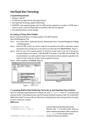
... DiskPart Disk Partitioning Tool to the size of the commands, be at the C:\> command prompt and press ). Intel Rapid Start Technology enabled in sequence. All motherboard drivers correctly installed B. For example, to set up Intel Rapid Start Store Partition Open the command prompt window and run diskpart.exe (enter "diskpart" at...
... DiskPart Disk Partitioning Tool to the size of the commands, be at the C:\> command prompt and press ). Intel Rapid Start Technology enabled in sequence. All motherboard drivers correctly installed B. For example, to set up Intel Rapid Start Store Partition Open the command prompt window and run diskpart.exe (enter "diskpart" at...
User Guide
Page 2
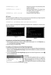
... SSD after completing the commands above. Enabling the Intel Rapid Start Technology in the notification area. The Timer slider in the operating system, insert the motherboard driver disk, go to Application Software\Install Application Software, and select Intel Rapid Start Technology to enter the BIOS Setup program. Save the settings and...
... SSD after completing the commands above. Enabling the Intel Rapid Start Technology in the notification area. The Timer slider in the operating system, insert the motherboard driver disk, go to Application Software\Install Application Software, and select Intel Rapid Start Technology to enter the BIOS Setup program. Save the settings and...
User Guide
Page 3
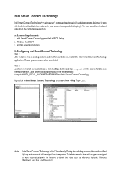
... while your computer when completed. Normal network connection B. Look for S3 mode only. A. Configuring Intel Smart Connect Technology Step 1: After installing the operating system and motherboard drivers, install the Intel Smart Connect Technology application. Step 2: As shown in the left screenshot below, click the Start button and type regedit in the...
... while your computer when completed. Normal network connection B. Look for S3 mode only. A. Configuring Intel Smart Connect Technology Step 1: After installing the operating system and motherboard drivers, install the Intel Smart Connect Technology application. Step 2: As shown in the left screenshot below, click the Start button and type regedit in the...
User Guide
Page 5
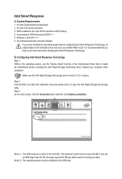
...click the Accelerate button and then click Enable acceleration. The maximum cache memory size is recommended that you enable RAID mode. All motherboard drivers correctly installed If you use the "Xpress Install" function of the hard disk. B. Step 2: Find the IRST icon in...to the SATA disk. If you have installed the operating system before enabling the Smart Response Technology. System Requirements 1. An Intel Chipset-based motherboard 2. An Intel Core series processor 3. Make sure the Intel Rapid Storage Technology driver version is 11.0 or above. Intel Smart Response A....
...click the Accelerate button and then click Enable acceleration. The maximum cache memory size is recommended that you enable RAID mode. All motherboard drivers correctly installed If you use the "Xpress Install" function of the hard disk. B. Step 2: Find the IRST icon in...to the SATA disk. If you have installed the operating system before enabling the Smart Response Technology. System Requirements 1. An Intel Chipset-based motherboard 2. An Intel Core series processor 3. Make sure the Intel Rapid Storage Technology driver version is 11.0 or above. Intel Smart Response A....
Manual
Page 2
Motherboard GA-Z77X-D3H Feb. 24, 2012 Motherboard GA-Z77X-D3H Feb. 24, 2012
Motherboard GA-Z77X-D3H Feb. 24, 2012 Motherboard GA-Z77X-D3H Feb. 24, 2012
Manual
Page 3
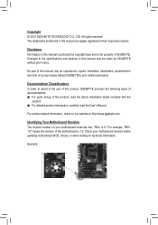
... TECHNOLOGY CO., LTD. Disclaimer Information in this manual may be made by GIGABYTE without GIGABYTE's prior written permission. For product-related information, check on our website at: http://www.gigabyte.com Identifying Your Motherboard Revision The revision number on your motherboard revision before updating motherboard BIOS, drivers, or when looking for technical information. For example, "REV...
... TECHNOLOGY CO., LTD. Disclaimer Information in this manual may be made by GIGABYTE without GIGABYTE's prior written permission. For product-related information, check on our website at: http://www.gigabyte.com Identifying Your Motherboard Revision The revision number on your motherboard revision before updating motherboard BIOS, drivers, or when looking for technical information. For example, "REV...
Manual
Page 4
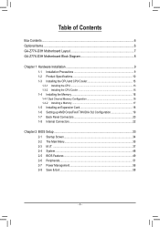
Table of Contents Box Contents...6 Optional Items...6 GA-Z77X-D3H Motherboard Layout 7 GA-Z77X-D3H Motherboard Block Diagram 8 Chapter 1 Hardware Installation 9 1-1 Installation Precautions 9 1-2 Product Specifications 10 1-3 Installing the CPU and CPU Cooler 13 1-3-1 Installing the CPU 13 1-3-2 Installing the CPU Cooler ...
Table of Contents Box Contents...6 Optional Items...6 GA-Z77X-D3H Motherboard Layout 7 GA-Z77X-D3H Motherboard Block Diagram 8 Chapter 1 Hardware Installation 9 1-1 Installation Precautions 9 1-2 Product Specifications 10 1-3 Installing the CPU and CPU Cooler 13 1-3-1 Installing the CPU 13 1-3-2 Installing the CPU Cooler ...
Manual
Page 6
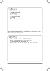
...-2SERPW-0*R) †† COM port cable (Part No. 12CF1-1CM001-3*R) †† 3.5" Front Panel with 2 USB 3.0/2.0 ports (Part No. 12CR1-FPX582-0*R) - 6 - Box Contents 55 GA-Z77X-D3H motherboard 55 Motherboard driver disk 55 User's Manual 55 Quick Installation Guide 55 Four SATA 6Gb/s cables 55 I/O Shield 55 One 2-Way SLI bridge connector The box contents...
...-2SERPW-0*R) †† COM port cable (Part No. 12CF1-1CM001-3*R) †† 3.5" Front Panel with 2 USB 3.0/2.0 ports (Part No. 12CR1-FPX582-0*R) - 6 - Box Contents 55 GA-Z77X-D3H motherboard 55 Motherboard driver disk 55 User's Manual 55 Quick Installation Guide 55 Four SATA 6Gb/s cables 55 I/O Shield 55 One 2-Way SLI bridge connector The box contents...
Manual
Page 7
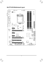
GA-Z77X-D3H Motherboard Layout SYS_FAN2 KB_MS_USB DVI VGA SYS_FAN3 ATX_12V CPU_FAN LGA1155 HDMI R_USB30_1 R_USB30_2 USB30_LAN VIA VL800 AUDIO BAT F_USB30 PCIEX1_1 MSATA ATX Atheros GbE LAN PCIEX16 DDR3_3 DDR3_1 DDR3_4 DDR3_2 0 1 CODEC PCIEX1_2 PCIEX1_3 PCIEX8 B_BIOS M_BIOS GA-Z77X-D3H PCI PCIe to PCI Bridge PCIEX4 F_AUDIO TPM SPDIF_O COMA F_USB2 F_USB1 SATA3 42 53 Intel® Z77 SATA2 Marvell 88SE9172 6 7 iTE Super I/O CLR_CMOS F_PANEL GSATA3 SYS_FAN1 - 7 -
GA-Z77X-D3H Motherboard Layout SYS_FAN2 KB_MS_USB DVI VGA SYS_FAN3 ATX_12V CPU_FAN LGA1155 HDMI R_USB30_1 R_USB30_2 USB30_LAN VIA VL800 AUDIO BAT F_USB30 PCIEX1_1 MSATA ATX Atheros GbE LAN PCIEX16 DDR3_3 DDR3_1 DDR3_4 DDR3_2 0 1 CODEC PCIEX1_2 PCIEX1_3 PCIEX8 B_BIOS M_BIOS GA-Z77X-D3H PCI PCIe to PCI Bridge PCIEX4 F_AUDIO TPM SPDIF_O COMA F_USB2 F_USB1 SATA3 42 53 Intel® Z77 SATA2 Marvell 88SE9172 6 7 iTE Super I/O CLR_CMOS F_PANEL GSATA3 SYS_FAN1 - 7 -
Manual
Page 8
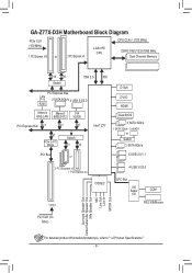
GA-Z77X-D3H Motherboard Block Diagram PCIe CLK (100 MHz) 1 PCI Express x16 or 2 PCI Express x8 LGA1155 CPU CPU CLK+/- (100 MHz) DDR3 1600/1333/1066 MHz Dual ...
GA-Z77X-D3H Motherboard Block Diagram PCIe CLK (100 MHz) 1 PCI Express x16 or 2 PCI Express x8 LGA1155 CPU CPU CLK+/- (100 MHz) DDR3 1600/1333/1066 MHz Dual ...
Manual
Page 9
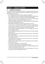
...for warranty validation. •• Always remove the AC power by your dealer. Chapter 1 Hardware Installation 1-1 Installation Precautions The motherboard contains numerous delicate electronic circuits and components which can lead to damage to system components as well as a result of electrostatic discharge... (ESD). These stickers are required for the motherboard. •• Prior to installation, do not remove or break motherboard S/N (Serial Number) sticker or warranty sticker provided by unplugging the power cord from the...
...for warranty validation. •• Always remove the AC power by your dealer. Chapter 1 Hardware Installation 1-1 Installation Precautions The motherboard contains numerous delicate electronic circuits and components which can lead to damage to system components as well as a result of electrostatic discharge... (ESD). These stickers are required for the motherboard. •• Prior to installation, do not remove or break motherboard S/N (Serial Number) sticker or warranty sticker provided by unplugging the power cord from the...
Manual
Page 12
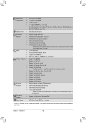
... for Q-Flash ŠŠ Support for Xpress Install ŠŠ Support for Xpress Recovery2 Š Support for EasyTune * Available functions in EasyTune may differ by motherboard model. ŠŠ Support for eXtreme Hard Drive (X.H.D) ŠŠ Support for Auto Green ŠŠ Support for ON/OFF Charge ŠŠ Support for...
... for Q-Flash ŠŠ Support for Xpress Install ŠŠ Support for Xpress Recovery2 Š Support for EasyTune * Available functions in EasyTune may differ by motherboard model. ŠŠ Support for eXtreme Hard Drive (X.H.D) ŠŠ Support for Auto Green ŠŠ Support for ON/OFF Charge ŠŠ Support for...
Manual
Page 13
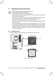
...Pin One Marking on the CPU. LGA1155 CPU Socket Alignment Key Alignment Key Pin One Corner of the CPU. Locate the alignment keys on the motherboard CPU socket and the notches on the CPU - 13 - It is not installed, otherwise overheating and damage of the CPU may locate the... for the latest CPU support list.) •• Always turn on the computer if the CPU cooler is not recommended that the motherboard supports the CPU. (Go to GIGABYTE's website for the peripherals. If you may occur. •• Set the CPU host frequency in accordance with the CPU specifications....
...Pin One Marking on the CPU. LGA1155 CPU Socket Alignment Key Alignment Key Pin One Corner of the CPU. Locate the alignment keys on the motherboard CPU socket and the notches on the CPU - 13 - It is not installed, otherwise overheating and damage of the CPU may locate the... for the latest CPU support list.) •• Always turn on the computer if the CPU cooler is not recommended that the motherboard supports the CPU. (Go to GIGABYTE's website for the peripherals. If you may occur. •• Set the CPU host frequency in accordance with the CPU specifications....
Manual
Page 14
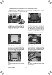
... CPU is not installed.) Step 3: Hold the CPU with your thumb to lift up the front edge (next to correctly install the CPU into the motherboard CPU socket. B. To protect the CPU socket, always replace the protective socket cover when the CPU is properly inserted, use the other to the CPU...
... CPU is not installed.) Step 3: Hold the CPU with your thumb to lift up the front edge (next to correctly install the CPU into the motherboard CPU socket. B. To protect the CPU socket, always replace the protective socket cover when the CPU is properly inserted, use the other to the CPU...
Manual
Page 15
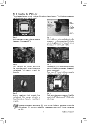
Inadequately removing the CPU cooler may adhere to remove the cooler, on the motherboard. 1-3-2 Installing the CPU Cooler Follow the steps below to correctly install the CPU cooler on the motherboard. (The following procedure uses Intel® boxed cooler as the picture above shows, the installation... is to your CPU cooler installation manual for instructions on the motherboard. Push down each push pin. Step 4: You should hear a "click" when pushing down on the surface of the installed CPU....
Inadequately removing the CPU cooler may adhere to remove the cooler, on the motherboard. 1-3-2 Installing the CPU Cooler Follow the steps below to correctly install the CPU cooler on the motherboard. (The following procedure uses Intel® boxed cooler as the picture above shows, the installation... is to your CPU cooler installation manual for instructions on the motherboard. Push down each push pin. Step 4: You should hear a "click" when pushing down on the surface of the installed CPU....
Manual
Page 16
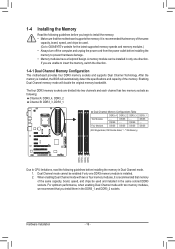
... - Hardware Installation - 16 - For optimum performance, when enabling Dual Channel mode with two or four memory modules, it is recommended that the motherboard supports the memory. 1-4 Installing the Memory Read the following guidelines before you begin to prevent hardware damage. •• Memory modules have a ...capacity, brand, speed, and chips be installed in the same colored DDR3 sockets. A memory module can be used . (Go to GIGABYTE's website for the latest supported memory speeds and memory modules.) •• Always turn off the computer and unplug the power cord ...
... - Hardware Installation - 16 - For optimum performance, when enabling Dual Channel mode with two or four memory modules, it is recommended that the motherboard supports the memory. 1-4 Installing the Memory Read the following guidelines before you begin to prevent hardware damage. •• Memory modules have a ...capacity, brand, speed, and chips be installed in the same colored DDR3 sockets. A memory module can be used . (Go to GIGABYTE's website for the latest supported memory speeds and memory modules.) •• Always turn off the computer and unplug the power cord ...
Manual
Page 17
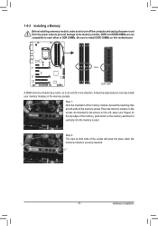
... DDR DIMMs. Be sure to install DDR3 DIMMs on the socket. Follow the steps below to the memory module. Place the memory module on this motherboard. 1-4-2 Installing a Memory Before installing a memory module, make sure to turn off the computer and unplug the power cord from the power outlet to prevent damage...
... DDR DIMMs. Be sure to install DDR3 DIMMs on the socket. Follow the steps below to the memory module. Place the memory module on this motherboard. 1-4-2 Installing a Memory Before installing a memory module, make sure to turn off the computer and unplug the power cord from the power outlet to prevent damage...
Manual
Page 18
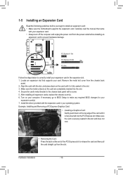
... your computer. 1-5 Installing an Expansion Card Read the following guidelines before installing an expansion card to install an expansion card: •• Make sure the motherboard supports the expansion card.
... your computer. 1-5 Installing an Expansion Card Read the following guidelines before installing an expansion card to install an expansion card: •• Make sure the motherboard supports the expansion card.
Manual
Page 19
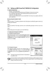
... and driver version. Step 3: Plug the display cable into the graphics card on top of identical brand and chip and correct driver -- A CrossFireX/SLI-supported motherboard with two PCI Express x16 slots and correct driver -- Hardware Installation CrossFireX(Note)/SLI bridge connectors -- Step 2: Insert the CrossFireX(Note)/SLI bridge connectors in...
... and driver version. Step 3: Plug the display cable into the graphics card on top of identical brand and chip and correct driver -- A CrossFireX/SLI-supported motherboard with two PCI Express x16 slots and correct driver -- Hardware Installation CrossFireX(Note)/SLI bridge connectors -- Step 2: Insert the CrossFireX(Note)/SLI bridge connectors in...
Manual
Page 21
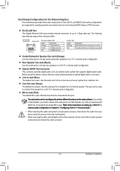
...connected to this audio jack to 1 Gbps data rate. Rear Speaker Out Jack (Black) Use this audio jack for the Onboard Graphics: This motherboard provides three video output ports: D-Sub, DVI-D, and HDMI. Use this audio jack to perform different functions via the audio software. The ...audio jacks can be connected to connect front speakers in jack. Use this feature, ensure that your device and then remove it from the motherboard. •• When removing the cable, pull it side to side to an external audio system that supports digital optical audio. Hardware ...
...connected to this audio jack to 1 Gbps data rate. Rear Speaker Out Jack (Black) Use this audio jack for the Onboard Graphics: This motherboard provides three video output ports: D-Sub, DVI-D, and HDMI. Use this audio jack to perform different functions via the audio software. The ...audio jacks can be connected to connect front speakers in jack. Use this feature, ensure that your device and then remove it from the motherboard. •• When removing the cable, pull it side to side to an external audio system that supports digital optical audio. Hardware ...


