
User Manual
Page 3
...Manual. Check your motherboard looks like this manual may be reproduced, copied, translated, transmitted, or published in this product, GIGABYTE provides the following types of documentations: „„ For quick set-up of this manual are legally registered to the specifications... Example: For product-related information, check on our website at: http://www.gigabyte.com Identifying Your Motherboard Revision The revision number on your motherboard revision before updating motherboard BIOS, drivers, or when looking for technical information. The trademarks mentioned in any ...
...Manual. Check your motherboard looks like this manual may be reproduced, copied, translated, transmitted, or published in this product, GIGABYTE provides the following types of documentations: „„ For quick set-up of this manual are legally registered to the specifications... Example: For product-related information, check on our website at: http://www.gigabyte.com Identifying Your Motherboard Revision The revision number on your motherboard revision before updating motherboard BIOS, drivers, or when looking for technical information. The trademarks mentioned in any ...

User Manual
Page 4
Table of Contents Box Contents...6 Optional Items...6 GA-Z77MX-D3H Motherboard Layout 7 GA-Z77MX-D3H Motherboard Block Diagram 8 Chapter 1 Hardware Installation 9 1-1 Installation Precautions 9 1-2 Product Specifications 10 1-3 Installing the CPU and CPU Cooler 13 ... Card 18 1-6 Setting up AMD CrossFireX™/NVIDIA SLI Configuration 19 1-7 Back Panel Connectors 20 1-8 Internal Connectors 22 Chapter 2 BIOS Setup 31 2-1 Startup Screen 32 2-2 The Main Menu 33 2-3 M.I.T...35 2-4 System...45 2-5 BIOS Features 46 2-6 Peripherals...48 2-7 Power Management 52 2-8 Save & Exit...54 - 4 -
Table of Contents Box Contents...6 Optional Items...6 GA-Z77MX-D3H Motherboard Layout 7 GA-Z77MX-D3H Motherboard Block Diagram 8 Chapter 1 Hardware Installation 9 1-1 Installation Precautions 9 1-2 Product Specifications 10 1-3 Installing the CPU and CPU Cooler 13 ... Card 18 1-6 Setting up AMD CrossFireX™/NVIDIA SLI Configuration 19 1-7 Back Panel Connectors 20 1-8 Internal Connectors 22 Chapter 2 BIOS Setup 31 2-1 Startup Screen 32 2-2 The Main Menu 33 2-3 M.I.T...35 2-4 System...45 2-5 BIOS Features 46 2-6 Peripherals...48 2-7 Power Management 52 2-8 Save & Exit...54 - 4 -
User Manual
Page 5
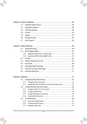
... 56 3-4 Contact...57 3-5 System...57 3-6 Download Center 58 3-7 New Program 58 Chapter 4 Unique Features 59 4-1 Xpress Recovery2 59 4-2 BIOS Update Utilities 62 4-2-1 Updating the BIOS with the Q-Flash Utility 62 4-2-2 Updating the BIOS with the @BIOS Utility 65 4-3 Q-Share...66 4-4 eXtreme Hard Drive (X.H.D 67 4-5 Auto Green...68 4-6 Intel Rapid Start Technology 69 4-7 Intel Smart...
... 56 3-4 Contact...57 3-5 System...57 3-6 Download Center 58 3-7 New Program 58 Chapter 4 Unique Features 59 4-1 Xpress Recovery2 59 4-2 BIOS Update Utilities 62 4-2-1 Updating the BIOS with the Q-Flash Utility 62 4-2-2 Updating the BIOS with the @BIOS Utility 65 4-3 Q-Share...66 4-4 eXtreme Hard Drive (X.H.D 67 4-5 Auto Green...68 4-6 Intel Rapid Start Technology 69 4-7 Intel Smart...

User Manual
Page 8
GA-Z77MX-D3H Motherboard Block Diagram 2 PCI Express x8 1 PCI Express x16 CPU CLK+/- (100 MHz) PCIe CLK or (100 MHz) LGA1155 CPU DDR3 1600(Note 1)/1333/1066 MHz Dual Channel Memory DMI 2.0 FDI x16 x8 Switch PCI Express Bus HDMI DVI-D D-Sub 1 PCI Express x4 1 PCI Express x1 Intel® Z77 Dual BIOS 2 SATA...
GA-Z77MX-D3H Motherboard Block Diagram 2 PCI Express x8 1 PCI Express x16 CPU CLK+/- (100 MHz) PCIe CLK or (100 MHz) LGA1155 CPU DDR3 1600(Note 1)/1333/1066 MHz Dual Channel Memory DMI 2.0 FDI x16 x8 Switch PCI Express Bus HDMI DVI-D D-Sub 1 PCI Express x4 1 PCI Express x1 Intel® Z77 Dual BIOS 2 SATA...

User Manual
Page 12
Hardware ŠŠ Monitor ŠŠ ŠŠ ŠŠ ŠŠ Š Š BIOS ŠŠ ŠŠ ŠŠ ŠŠ Unique Features ŠŠ ŠŠ ŠŠ ŠŠ ŠŠ ŠŠ ŠŠ... will depend on the CPU/system cooler you install. 2 x 64 Mbit flash Use of licensed AMI EFI BIOS Support for DualBIOS™ PnP 1.0a, DMI 2.0, SM BIOS 2.6, ACPI 2.0a Support for @BIOS Support for Q-Flash Support for Xpress Install Support for Xpress Recovery2 Support for eXtreme Hard Drive (X.H.D) Support for ...
Hardware ŠŠ Monitor ŠŠ ŠŠ ŠŠ ŠŠ Š Š BIOS ŠŠ ŠŠ ŠŠ ŠŠ Unique Features ŠŠ ŠŠ ŠŠ ŠŠ ŠŠ ŠŠ ŠŠ... will depend on the CPU/system cooler you install. 2 x 64 Mbit flash Use of licensed AMI EFI BIOS Support for DualBIOS™ PnP 1.0a, DMI 2.0, SM BIOS 2.6, ACPI 2.0a Support for @BIOS Support for Q-Flash Support for Xpress Install Support for Xpress Recovery2 Support for eXtreme Hard Drive (X.H.D) Support for ...

User Manual
Page 16
... DS=Double-Sided, "- -"=No Memory) DDR3_4 DDR3_2 DDR3_3 DDR3_1 Due to CPU limitations, read the following guidelines before installing the memory to GIGABYTE's website for the latest supported memory speeds and memory modules.) •• Always turn off the computer and unplug the power cord from the...we recommend that memory of the same capacity, brand, speed, and chips be enabled if only one DDR3 memory module is installed, the BIOS will double the original memory bandwidth. Dual Channel mode cannot be used . (Go to prevent hardware damage. •• Memory modules have ...
... DS=Double-Sided, "- -"=No Memory) DDR3_4 DDR3_2 DDR3_3 DDR3_1 Due to CPU limitations, read the following guidelines before installing the memory to GIGABYTE's website for the latest supported memory speeds and memory modules.) •• Always turn off the computer and unplug the power cord from the...we recommend that memory of the same capacity, brand, speed, and chips be enabled if only one DDR3 memory module is installed, the BIOS will double the original memory bandwidth. Dual Channel mode cannot be used . (Go to prevent hardware damage. •• Memory modules have ...

User Manual
Page 18
...;• Removing the Card: Press the latch at the end of the card until it is fully seated in your computer. If necessary, go to BIOS Setup to the chassis back panel with the slot, and press down on the card are completely inserted into the PCI Express slot. Turn on... inserted into the slot. 4. Hardware Installation - 18 - Carefully read the manual that supports your expansion card(s). 7. Secure the card's metal bracket to make any required BIOS changes for your card. Align the card with a screw. 5.
...;• Removing the Card: Press the latch at the end of the card until it is fully seated in your computer. If necessary, go to BIOS Setup to the chassis back panel with the slot, and press down on the card are completely inserted into the PCI Express slot. Turn on... inserted into the slot. 4. Hardware Installation - 18 - Carefully read the manual that supports your expansion card(s). 7. Secure the card's metal bracket to make any required BIOS changes for your card. Align the card with a screw. 5.

User Manual
Page 21
... (Orange) Use this audio jack to 1 Gbps data rate. Mic In Jack (Pink) The default Mic in operating system environment only, but not during the BIOS Setup or POST process. In addition to the default speakers settings, the ~ audio jacks can be used to connect front speakers in a 4/5.1/7.1-channel audio configuration...
... (Orange) Use this audio jack to 1 Gbps data rate. Mic In Jack (Pink) The default Mic in operating system environment only, but not during the BIOS Setup or POST process. In addition to the default speakers settings, the ~ audio jacks can be used to connect front speakers in a 4/5.1/7.1-channel audio configuration...

User Manual
Page 24
... control design. 3/4) CPU_FAN/SYS_FAN1/SYS_FAN2 (Fan Headers) All fan headers on the headers. 5) BAT (Battery) The battery provides power to keep the values (such as BIOS configurations, date, and time information) in the CMOS when the computer is turned off. Definition 1 GND 1 SYS_FAN2 2 +12V 3 Sense 4 Speed Control •• Be sure...
... control design. 3/4) CPU_FAN/SYS_FAN1/SYS_FAN2 (Fan Headers) All fan headers on the headers. 5) BAT (Battery) The battery provides power to keep the values (such as BIOS configurations, date, and time information) in the CMOS when the computer is turned off. Definition 1 GND 1 SYS_FAN2 2 +12V 3 Sense 4 Speed Control •• Be sure...

User Manual
Page 26
PW+ PWSPEAK+ SPEAK- 2 20 1 19 HD+ HD- The LED is off when the system is detected, the BIOS may issue beeps in S3/ S3/S4/S5 Off S4 sleep state or powered off your chassis front panel module to the reset switch on ... restart. •• CI (Chassis Intrusion Header, Gray): Connects to the pin assignments below. When connecting your system using the power switch (refer to Chapter 2, "BIOS Setup," "Power Management Setup," for information about beep codes. •• HD (Hard Drive Activity LED, Blue) Connects to the power status indicator on the...
PW+ PWSPEAK+ SPEAK- 2 20 1 19 HD+ HD- The LED is off when the system is detected, the BIOS may issue beeps in S3/ S3/S4/S5 Off S4 sleep state or powered off your chassis front panel module to the reset switch on ... restart. •• CI (Chassis Intrusion Header, Gray): Connects to the pin assignments below. When connecting your system using the power switch (refer to Chapter 2, "BIOS Setup," "Power Management Setup," for information about beep codes. •• HD (Hard Drive Activity LED, Blue) Connects to the power status indicator on the...

User Manual
Page 27
...unable to certain expansion cards like graphics cards and sound cards. DIP 10) SPDIF_O (S/PDIF Out Header) 1 2 3 SMB_CPT (GA-IVB) ThiPsChIeepaodweerrcsounpnepcotorrts(SdATigAi)t(aXl5S8A/-PODC)IF Out and connects a S/PDIF digital audio cable (provided by default. For information about connecting ... 5 Line Out (R) 6 GND 6 NC 7 FAUDIO_JD 7 NC 8 No Pin 8 No Pin 9 LINE2_L 9 Line Out (L) DIP 1 23 1 10 GND 10 NC BIOS Switcher (X58A-OC) DB_PORT •• The front panel audio header supports HD audio by expansion cards) for digital audio output from the HDMI display...
...unable to certain expansion cards like graphics cards and sound cards. DIP 10) SPDIF_O (S/PDIF Out Header) 1 2 3 SMB_CPT (GA-IVB) ThiPsChIeepaodweerrcsounpnepcotorrts(SdATigAi)t(aXl5S8A/-PODC)IF Out and connects a S/PDIF digital audio cable (provided by default. For information about connecting ... 5 Line Out (R) 6 GND 6 NC 7 FAUDIO_JD 7 NC 8 No Pin 8 No Pin 9 LINE2_L 9 Line Out (L) DIP 1 23 1 10 GND 10 NC BIOS Switcher (X58A-OC) DB_PORT •• The front panel audio header supports HD audio by expansion cards) for digital audio output from the HDMI display...

User Manual
Page 28
... two USB 3.0/2.0 ports, please contact the local dealer. 20 10 11 TPM w/housing Pin No. 1 2 3 4 5 6 7 8 9 10 Definition VBUS SSRX1SSRX1+ GND SSTX1SSTX1+ GND D1D1+ NC DB_PORT 1 BIOS Switc 1 1 Pin No. 11) F_USB1/F_USB2 (USB 2.0/1.1 Headers) The headers conform to the USB bracket. Definition 11 VolDta2ge+measurement module(X58A-OC) 12 D213 GND...
... two USB 3.0/2.0 ports, please contact the local dealer. 20 10 11 TPM w/housing Pin No. 1 2 3 4 5 6 7 8 9 10 Definition VBUS SSRX1SSRX1+ GND SSTX1SSTX1+ GND D1D1+ NC DB_PORT 1 BIOS Switc 1 1 Pin No. 11) F_USB1/F_USB2 (USB 2.0/1.1 Headers) The headers conform to the USB bracket. Definition 11 VolDta2ge+measurement module(X58A-OC) 12 D213 GND...
User Manual
Page 29
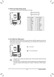
... the power outlet before clearing the CMOS values. •• After system restart, go to BIOS Setup to load factory defaults (select Load Optimized Defaults) or manually configure the BIOS settings (refer to touch the two pins for BIOS configurations). - 29 - Hardware Installation DB_PORT 13) TPM (Trusted Platform Module Header) You may connect... SERIRQ GND NC NC SUSCLK PCIe power connector (SATA)(X58A-OC) 14) CLR_CMOS (Clear CMOS Jumper) Use this jumper to factory defaults. date information and BIOS configurations) and reset the CMOS values to clear the CMOS values (e.g.
... the power outlet before clearing the CMOS values. •• After system restart, go to BIOS Setup to load factory defaults (select Load Optimized Defaults) or manually configure the BIOS settings (refer to touch the two pins for BIOS configurations). - 29 - Hardware Installation DB_PORT 13) TPM (Trusted Platform Module Header) You may connect... SERIRQ GND NC NC SUSCLK PCIe power connector (SATA)(X58A-OC) 14) CLR_CMOS (Clear CMOS Jumper) Use this jumper to factory defaults. date information and BIOS configurations) and reset the CMOS values to clear the CMOS values (e.g.

User Manual
Page 31
... not alter the default settings (unless you not flash the BIOS. To upgrade the BIOS, use either the GIGABYTE Q-Flash or @BIOS utility. •• Q-Flash allows the user to quickly and easily upgrade or back up BIOS without entering the operating system. •• @BIOS is recommended that allows the user to modify basic system...
... not alter the default settings (unless you not flash the BIOS. To upgrade the BIOS, use either the GIGABYTE Q-Flash or @BIOS utility. •• Q-Flash allows the user to quickly and easily upgrade or back up BIOS without entering the operating system. •• @BIOS is recommended that allows the user to modify basic system...

User Manual
Page 32
... Press the key to access the Q-Flash utility directly without having to set the first boot device without entering BIOS Setup. Function Keys Function Keys: : BIOS SETUP\Q-FLASH Press the key to enter BIOS Setup or to access the Q-Flash utility in Boot Menu is effective for one time only. Note: The setting.... : SYSTEM INFORMATION Press the key to display your system information. : BOOT MENU Boot Menu allows you to enter BIOS Setup first. In Boot Menu, use the up arrow key or the down arrow key to select the first boot device, then press to accept. ...
... Press the key to access the Q-Flash utility directly without having to set the first boot device without entering BIOS Setup. Function Keys Function Keys: : BIOS SETUP\Q-FLASH Press the key to enter BIOS Setup or to access the Q-Flash utility in Boot Menu is effective for one time only. Note: The setting.... : SYSTEM INFORMATION Press the key to display your system information. : BOOT MENU Boot Menu allows you to enter BIOS Setup first. In Boot Menu, use the up arrow key or the down arrow key to select the first boot device, then press to accept. ...

User Manual
Page 33
... the function menu icons at the bottom of the screen or press to switch to the main menu of the BIOS Setup Program.) B. The 3D BIOS Screen (Default) On GIGABYTE's uniquely designed 3D BIOS screen, you can use your mouse to select the item you can use your mouse arrow over the CPU and... memory sockets and enter the System Tuning menu to the main menu of the BIOS Setup program. (If a mouse is not connected...
... the function menu icons at the bottom of the screen or press to switch to the main menu of the BIOS Setup Program.) B. The 3D BIOS Screen (Default) On GIGABYTE's uniquely designed 3D BIOS screen, you can use your mouse to select the item you can use your mouse arrow over the CPU and... memory sockets and enter the System Tuning menu to the main menu of the BIOS Setup program. (If a mouse is not connected...

User Manual
Page 34
... Increase the numeric value or make changes / Decrease the numeric value or make changes Switch to 3D BIOS screen Restore the previous BIOS settings for the current submenus Load the Optimized BIOS default settings for the current submenus Access the Q-Flash utility Display system information Save all the changes made... Use this menu to configure all the power-saving functions. „„ Save & Exit Save all the changes and exit the BIOS Setup program Capture the current screen as usual, select the Load Optimized Defaults item to set your CPU and memory, etc.
... Increase the numeric value or make changes / Decrease the numeric value or make changes Switch to 3D BIOS screen Restore the previous BIOS settings for the current submenus Load the Optimized BIOS default settings for the current submenus Access the Q-Flash utility Display system information Save all the changes made... Use this menu to configure all the power-saving functions. „„ Save & Exit Save all the changes and exit the BIOS Setup program Capture the current screen as usual, select the Load Optimized Defaults item to set your CPU and memory, etc.

User Manual
Page 35
... values.) This section provides information on your overall system configurations. This page is dependent on the BIOS version, CPU base clock, CPU frequency, memory frequency, total memory size , CPU temperature, Vcore, and memory voltage. - 35 - BIOS Setup Whether the system will work stably with the overclock/overvoltage settings you made is for...
... values.) This section provides information on your overall system configurations. This page is dependent on the BIOS version, CPU base clock, CPU frequency, memory frequency, total memory size , CPU temperature, Vcore, and memory voltage. - 35 - BIOS Setup Whether the system will work stably with the overclock/overvoltage settings you made is for...

User Manual
Page 36
Current Status This screen provides information on the CPU being installed. && CPU Frequency Displays the current operating CPU frequency. BIOS Setup - 36 - The adjustable range is from 400 MHz to 3200 MHz. (Default: Auto) && CPU Clock Ratio Allows you to alter the clock ratio for ...
Current Status This screen provides information on the CPU being installed. && CPU Frequency Displays the current operating CPU frequency. BIOS Setup - 36 - The adjustable range is from 400 MHz to 3200 MHz. (Default: Auto) && CPU Clock Ratio Allows you to alter the clock ratio for ...

User Manual
Page 37
...about Intel CPUs' unique features, please visit Intel's website. - 37 - This feature only works for CPU Turbo mode. Auto lets the BIOS automatically configure this setting. (Default: Auto) (Note) This item is present only when you to set a current limit for operating systems... that supports this feature. BIOS Setup Auto lets the BIOS automatically configure this setting. (Default: Auto) && Hyper-Threading Technology (Note) Allows you to determine whether to enable multi-threading...
...about Intel CPUs' unique features, please visit Intel's website. - 37 - This feature only works for CPU Turbo mode. Auto lets the BIOS automatically configure this setting. (Default: Auto) (Note) This item is present only when you to set a current limit for operating systems... that supports this feature. BIOS Setup Auto lets the BIOS automatically configure this setting. (Default: Auto) && Hyper-Threading Technology (Note) Allows you to determine whether to enable multi-threading...


