User Manual
Page 5
... 62 4-2-2 Updating the BIOS with the @BIOS Utility 65 4-3 Q-Share...66 4-4 eXtreme Hard Drive (X.H.D 67 4-5 Auto Green...68 4-6 Intel Rapid Start Technology 69 4-7 Intel Smart Connect Technology 71 4-8 Intel Smart Response 73 Chapter 5 Appendix...75 5-1 Configuring SATA Hard Drive(s 75 5-1-1 Configuring SATA Controllers 75 5-1-2 Installing the SATA RAID/AHCI Driver and...
... 62 4-2-2 Updating the BIOS with the @BIOS Utility 65 4-3 Q-Share...66 4-4 eXtreme Hard Drive (X.H.D 67 4-5 Auto Green...68 4-6 Intel Rapid Start Technology 69 4-7 Intel Smart Connect Technology 71 4-8 Intel Smart Response 73 Chapter 5 Appendix...75 5-1 Configuring SATA Hard Drive(s 75 5-1-1 Configuring SATA Controllers 75 5-1-2 Installing the SATA RAID/AHCI Driver and...
User Manual
Page 9
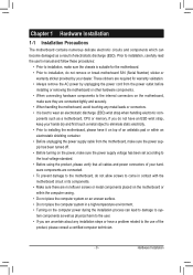
...electronic com- Prior to installation, carefully read the user's manual and follow these procedures: • Prior to installation, make sure they are connected. • To prevent damage to the motherboard, do not remove or break motherboard S/N (Serial Number) sticker or warranty sticker provided by ... local voltage standard. • Before using the product, please verify that all cables and power connectors of your hardware components are connected tightly and securely. • When handling the motherboard, avoid touching any installation steps or have it on top of an antistatic ...
...electronic com- Prior to installation, carefully read the user's manual and follow these procedures: • Prior to installation, make sure they are connected. • To prevent damage to the motherboard, do not remove or break motherboard S/N (Serial Number) sticker or warranty sticker provided by ... local voltage standard. • Before using the product, please verify that all cables and power connectors of your hardware components are connected tightly and securely. • When handling the motherboard, avoid touching any installation steps or have it on top of an antistatic ...
User Manual
Page 10
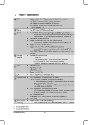
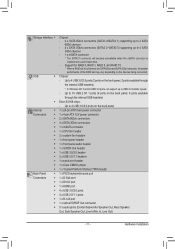
Dual channel memory architecture Support for GA-Z77-D3H. The PCIEX1_2/3 slots will become unavailable when... x PCI Express x16 slot, running at up to x4 mode when AMD CrossFireX™ is enabled. k (Go to GIGABYTE's website for the latest supported memory speeds and memory modules.) Integrated Graphics Processor: - 1 x D-Sub port - 1 ...x DVI-D port, supporting a maximum resolution of 1920x1200 * The DVI-D port does not support D-Sub connection by adapter. - 1 x HDMI port, supporting a maximum resolution of 1920x1200 VIA VT2021 codec High Definition Audio 2/4/5.1/7.1-channel Support...
Dual channel memory architecture Support for GA-Z77-D3H. The PCIEX1_2/3 slots will become unavailable when... x PCI Express x16 slot, running at up to x4 mode when AMD CrossFireX™ is enabled. k (Go to GIGABYTE's website for the latest supported memory speeds and memory modules.) Integrated Graphics Processor: - 1 x D-Sub port - 1 ...x DVI-D port, supporting a maximum resolution of 1920x1200 * The DVI-D port does not support D-Sub connection by adapter. - 1 x HDMI port, supporting a maximum resolution of 1920x1200 VIA VT2021 codec High Definition Audio 2/4/5.1/7.1-channel Support...
User Manual
Page 11
... can support up to USB 2.0 transfer speed. - Support for RAID 0, RAID 1, RAID 5, and RAID 10 * When a RAID set may vary depending on the devices being connected. Chipset: - Up to 2 USB 3.0/2.0 ports on the back panel 1 x 24-pin ATX main power connector 1 x 4-pin ATX 12V power connector 2 x SATA 6Gb/s connectors 4 x SATA 3Gb...
... can support up to USB 2.0 transfer speed. - Support for RAID 0, RAID 1, RAID 5, and RAID 10 * When a RAID set may vary depending on the devices being connected. Chipset: - Up to 2 USB 3.0/2.0 ports on the back panel 1 x 24-pin ATX main power connector 1 x 4-pin ATX 12V power connector 2 x SATA 6Gb/s connectors 4 x SATA 3Gb...
User Manual
Page 12
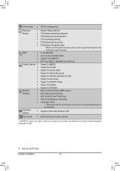
... Internet Security (OEM version) Intel® Rapid Start Technology Intel® Smart Connect Technology Intel® Smart Response Technology LucidLogix Virtuj * Make sure the monitor cable has been connected to the product specifications and product-related information without prior notice. I/O Controller ... the back panel. Support for Microsoft® Windows 7/XP ATX Form Factor; 30.5cm x 24.4cm * GIGABYTE reserves the right to make any changes to the integrated graphics port on the CPU/system cooler you install. 2... Support for ON/OFF Charge Support for Q-Share Support for GA-Z77-D3H.
... Internet Security (OEM version) Intel® Rapid Start Technology Intel® Smart Connect Technology Intel® Smart Response Technology LucidLogix Virtuj * Make sure the monitor cable has been connected to the product specifications and product-related information without prior notice. I/O Controller ... the back panel. Support for Microsoft® Windows 7/XP ATX Form Factor; 30.5cm x 24.4cm * GIGABYTE reserves the right to make any changes to the integrated graphics port on the CPU/system cooler you install. 2... Support for ON/OFF Charge Support for Q-Share Support for GA-Z77-D3H.
User Manual
Page 19
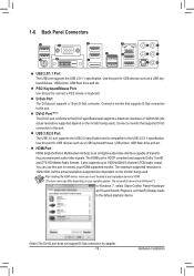
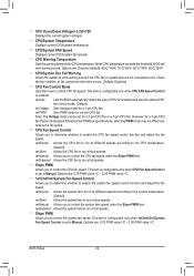
... operating system. The HDMI port is compatible to the default playback device. (Note) The DVI-D port does not support D-Sub connection by adapter. - 19 - USB 3.0/2.0 Port The USB 3.0 port supports the USB 3.0 specification and is HDCP compliant and supports Dolby TrueHD and ... below is 1920x1200, but the actual resolutions supported are dependent on the monitor being used . DVI-D Port (Note) The DVI-D port conforms to connect a PS/2 mouse or keyboard. HDMI Port HDMI (High-Definition Multimedia Interface) is an all-digital audio/video interface capable of 1920x1200 (the actual ...
... operating system. The HDMI port is compatible to the default playback device. (Note) The DVI-D port does not support D-Sub connection by adapter. - 19 - USB 3.0/2.0 Port The USB 3.0 port supports the USB 3.0 specification and is HDCP compliant and supports Dolby TrueHD and ... below is 1920x1200, but the actual resolutions supported are dependent on the monitor being used . DVI-D Port (Note) The DVI-D port conforms to connect a PS/2 mouse or keyboard. HDMI Port HDMI (High-Definition Multimedia Interface) is an all-digital audio/video interface capable of 1920x1200 (the actual ...
User Manual
Page 20
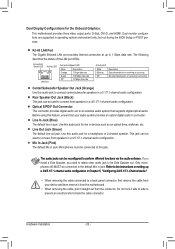
... the motherboard. • When removing the cable, pull it side to side to 1 Gbps data rate. This jack can be connected to connect front speakers in a 4/5.1/7.1-channel audio configuration. Before using this audio jack to perform different functions via the audio software. If you... install a Side Speaker, you need to retask other audio jack to be reconfigured to connect center/subwoofer speakers in a 4/5.1/7.1-channel audio configuration. Hardware Installation - 20 - Line In Jack (Blue) The default line in jack....
... the motherboard. • When removing the cable, pull it side to side to 1 Gbps data rate. This jack can be connected to connect front speakers in a 4/5.1/7.1-channel audio configuration. Before using this audio jack to perform different functions via the audio software. If you... install a Side Speaker, you need to retask other audio jack to be reconfigured to connect center/subwoofer speakers in a 4/5.1/7.1-channel audio configuration. Hardware Installation - 20 - Line In Jack (Blue) The default line in jack....
User Manual
Page 21
... on the motherboard. - 21 - Unplug the power cord from the power outlet to prevent damage to the devices. • After installing the device and before connecting external devices: • First make sure the device cable has been securely attached to turn off the devices and your devices are compliant with the...
... on the motherboard. - 21 - Unplug the power cord from the power outlet to prevent damage to the devices. • After installing the device and before connecting external devices: • First make sure the device cable has been securely attached to turn off the devices and your devices are compliant with the...
User Manual
Page 22
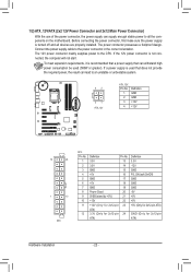
... does not provide the required power, the result can supply enough stable power to all devices are properly installed. Before connecting the power connector, first make sure the power supply is not connected, the computer will not start. 1/2) ATX_12V/ATX (2x2 12V Power Connector and 2x12 Main Power Connector) With the use... is turned off and all the components on the motherboard. The 12V power connector mainly supplies power to the power connector in the correct orientation. Connect the power supply cable to the CPU.
... does not provide the required power, the result can supply enough stable power to all devices are properly installed. Before connecting the power connector, first make sure the power supply is not connected, the computer will not start. 1/2) ATX_12V/ATX (2x2 12V Power Connector and 2x12 Main Power Connector) With the use... is turned off and all the components on the motherboard. The 12V power connector mainly supplies power to the power connector in the correct orientation. Connect the power supply cable to the CPU.
User Manual
Page 23
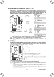
... computer. • Always turn off your computer and unplug the power cord. 2. Hardware Installation Replace the battery when the battery voltage drops to connect it is recommended that a system fan be handled in accordance with fan speed control design. The speed control function requires the use a metal object...). • Used batteries must be installed inside the chassis. CPU_FAN: Pin No. Definition 1 GND 2 +12V 3 Sense 4 Speed Control • Be sure to connect fan cables to the fan headers to prevent your CPU and system from the battery holder and wait for one .
... computer. • Always turn off your computer and unplug the power cord. 2. Hardware Installation Replace the battery when the battery voltage drops to connect it is recommended that a system fan be handled in accordance with fan speed control design. The speed control function requires the use a metal object...). • Used batteries must be installed inside the chassis. CPU_FAN: Pin No. Definition 1 GND 2 +12V 3 Sense 4 Speed Control • Be sure to connect fan cables to the fan headers to prevent your CPU and system from the battery holder and wait for one .
User Manual
Page 24
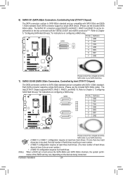
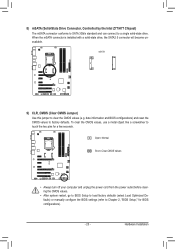
... Hardware Installation - 24 - The SATA3 0/1 connectors support RAID 0 and RAID 1. 6) SATA3 0/1 (SATA 6Gb/s Connectors, Controlled by Intel Z77/H77 Chipset) The SATA connectors conform to be used, the total number of hard drives must be im- RAID 5 and RAID 10 can... are compatible with the "SATA2 2/3/4/5" and mSATA connectors . (Note) Refer to Chapter 5, "Configuring SATA Hard Drive(s)," for instructions on the devices being connected. Each SATA connector supports a single SATA device. (Please use the included SATA 6Gb/s cable). Definition 1 GND SATA3 2 TXP 7 11 3 TXN ...
... Hardware Installation - 24 - The SATA3 0/1 connectors support RAID 0 and RAID 1. 6) SATA3 0/1 (SATA 6Gb/s Connectors, Controlled by Intel Z77/H77 Chipset) The SATA connectors conform to be used, the total number of hard drives must be im- RAID 5 and RAID 10 can... are compatible with the "SATA2 2/3/4/5" and mSATA connectors . (Note) Refer to Chapter 5, "Configuring SATA Hard Drive(s)," for instructions on the devices being connected. Each SATA connector supports a single SATA device. (Please use the included SATA 6Gb/s cable). Definition 1 GND SATA3 2 TXP 7 11 3 TXN ...
User Manual
Page 25
... solid-state drive. F_AUDIO(H) F_PANEL(NH) F_PANEL (H61M-D2) DB_PORT 8) mSATA (Solid-State Drive Connector, Controlled by the Intel Z77/H77 Chipset) The mSATA connector conforms to SATA 3Gb/s standard and can connect to factory defaults. Open: Normal Short: Clear CMOS Values • Always turn off your computer and unplug the power...
... solid-state drive. F_AUDIO(H) F_PANEL(NH) F_PANEL (H61M-D2) DB_PORT 8) mSATA (Solid-State Drive Connector, Controlled by the Intel Z77/H77 Chipset) The mSATA connector conforms to SATA 3Gb/s standard and can connect to factory defaults. Open: Normal Short: Clear CMOS Values • Always turn off your computer and unplug the power...
User Manual
Page 26
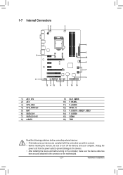
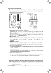
...Intrusion Header • MSG/PWR (Message/Power/Sleep LED, Yellow/Purple): System Status LED S0 On S1 Blinking S3/S4/S5 Off Connects to the chassis intrusion switch/sensor on the chassis that can detect if the chassis cover has been removed. The LED keeps blinking ...the system is operating. Hardware Installation - 26 - Message/Power/ Power Sleep LED Switch Speaker MSG+ MSG- 10) F_PANEL (Front Panel Header) Connect the power switch, reset switch, speaker, chassis intrusion switch/sensor and system status indicator on the chassis to this header, make sure the wire ...
...Intrusion Header • MSG/PWR (Message/Power/Sleep LED, Yellow/Purple): System Status LED S0 On S1 Blinking S3/S4/S5 Off Connects to the chassis intrusion switch/sensor on the chassis that can detect if the chassis cover has been removed. The LED keeps blinking ...the system is operating. Hardware Installation - 26 - Message/Power/ Power Sleep LED Switch Speaker MSG+ MSG- 10) F_PANEL (Front Panel Header) Connect the power switch, reset switch, speaker, chassis intrusion switch/sensor and system status indicator on the chassis to this header, make sure the wire ...
User Manual
Page 27
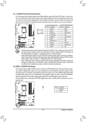
... panel audio module that has different wire assignments, please contact the chassis manufacturer. 12) SPDIF_O (S/PDIF Out Header) This header supports digital S/PDIF Out and connects a S/PDIF digital audio cable (provided by default. Definition 1 1 SPDIFO 2 GND - 27 - Definition 9 1 1 MIC2_L 1 MIC 10 2 2F_PANGELN(NDH) 3 MIC2_R 4 ... to the graphics card and have digital audio output from the HDMI display at the same time. For information about connecting the front panel audio module that has separated connectors on how to activate AC'97 functionality via the audio software in...
... panel audio module that has different wire assignments, please contact the chassis manufacturer. 12) SPDIF_O (S/PDIF Out Header) This header supports digital S/PDIF Out and connects a S/PDIF digital audio cable (provided by default. Definition 1 1 SPDIFO 2 GND - 27 - Definition 9 1 1 MIC2_L 1 MIC 10 2 2F_PANGELN(NDH) 3 MIC2_R 4 ... to the graphics card and have digital audio output from the HDMI display at the same time. For information about connecting the front panel audio module that has separated connectors on how to activate AC'97 functionality via the audio software in...
User Manual
Page 29
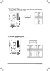
...) The COM header can provide one serial port via an optional COM port cable. F_AUDIO(H) No Pin 16) TPM (Trusted Platform Module Header) You may connect a TPM (Trusted Platform Module) to this header. 19 TPM w/housing 20 Pin No. 1 2 3 4 5 6 7 8 9 10 Definition LCLK GND LFRAME No Pin LRESET NC LAD3 LAD2 VCC3...
...) The COM header can provide one serial port via an optional COM port cable. F_AUDIO(H) No Pin 16) TPM (Trusted Platform Module Header) You may connect a TPM (Trusted Platform Module) to this header. 19 TPM w/housing 20 Pin No. 1 2 3 4 5 6 7 8 9 10 Definition LCLK GND LFRAME No Pin LRESET NC LAD3 LAD2 VCC3...
User Manual
Page 33
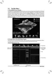
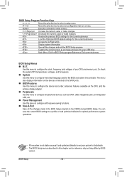
..., and voltage settings. Or you want. (Sample BIOS Version: F3c) Switch to the main menu of the BIOS Setup program. (If a mouse is not connected, the 3D BIOS screen will automatically switch to 3D BIOS Screen Setup Menus Enter Q-Flash Select Default Language Help Function Keys Configuration Items Current Settings...the bottom of the screen or press to switch to the main menu of the BIOS Setup Program.) B. The 3D BIOS Screen (Default) On GIGABYTE's uniquely designed 3D BIOS screen, you can use your mouse to move among the items and press to enter the function menu in each area...
..., and voltage settings. Or you want. (Sample BIOS Version: F3c) Switch to the main menu of the BIOS Setup program. (If a mouse is not connected, the 3D BIOS screen will automatically switch to 3D BIOS Screen Setup Menus Enter Q-Flash Select Default Language Help Function Keys Configuration Items Current Settings...the bottom of the screen or press to switch to the main menu of the BIOS Setup Program.) B. The 3D BIOS Screen (Default) On GIGABYTE's uniquely designed 3D BIOS screen, you can use your mouse to move among the items and press to enter the function menu in each area...
User Manual
Page 34
... LAN, etc. „ Power Management Use this menu to configure the default language used by BIOS version. This menu also displays information on the devices connected to the SATA ports. „ BIOS Features Use this menu to configure the device boot order, advanced features available on a menu Execute command or enter...
... LAN, etc. „ Power Management Use this menu to configure the default language used by BIOS version. This menu also displays information on the devices connected to the SATA ports. „ BIOS Features Use this menu to configure the device boot order, advanced features available on a menu Execute command or enter...
User Manual
Page 44
...can be set for a 4-pin CPU fan. When CPU temperature exceeds the threshold, BIOS will emit warning sound. However, for CPU temperature. Options are not connected or fail. & CPU Vcore/Dram Voltage/+3.3V/+12V Displays the current system voltages. & CPU/System Temperature Displays current CPU/system temperature. & CPU/System FAN... Allows the system fans to run at full speeds. & Slope PWM Allows you to control CPU fan speed. Check the fan condition or fan connection when this occurs. (Default: Disabled) & CPU Fan Control Mode Specifies how to control the CPU fan speed.
...can be set for a 4-pin CPU fan. When CPU temperature exceeds the threshold, BIOS will emit warning sound. However, for CPU temperature. Options are not connected or fail. & CPU Vcore/Dram Voltage/+3.3V/+12V Displays the current system voltages. & CPU/System Temperature Displays current CPU/system temperature. & CPU/System FAN... Allows the system fans to run at full speeds. & Slope PWM Allows you to control CPU fan speed. Check the fan condition or fan connection when this occurs. (Default: Disabled) & CPU Fan Control Mode Specifies how to control the CPU fan speed.
User Manual
Page 45
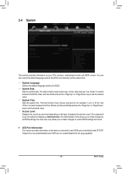
..., Date, and Year fields and use the or key to set the desired value. & Access Level Displays the current access level depending on the device connected to each SATA port or enable/disable the hot plug capability. - 45 - The time format is week (read-only), month, date and year. ...only allows you to make changes to all . ` ATA Port Information This section provides information on the type of password protection used by Intel Z77/H77 Chipset.You can also select the default language used by the BIOS and manually set the system time. & System Language Selects the default language...
..., Date, and Year fields and use the or key to set the desired value. & Access Level Displays the current access level depending on the device connected to each SATA port or enable/disable the hot plug capability. - 45 - The time format is week (read-only), month, date and year. ...only allows you to make changes to all . ` ATA Port Information This section provides information on the type of password protection used by Intel Z77/H77 Chipset.You can also select the default language used by the BIOS and manually set the system time. & System Language Selects the default language...
User Manual
Page 46
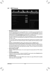
...the keyboard after the POST. (Default: Enabled) & Full Screen LOGO Show Allows you to determine which Option ROM to launch. Options are connected. To boot from an operating system that support Boot from the available devices. This item is installed. & Bootup NumLock State Enables or ... format will be prefixed with the highest priority for a specific device type, such as the second priority (Boot Option #2). Disabled skips the GIGABYTE Logo when the system starts up. (Default: Enabled) & PCI ROM Priority Allows you to determine whether to install an operating system that...
...the keyboard after the POST. (Default: Enabled) & Full Screen LOGO Show Allows you to determine which Option ROM to launch. Options are connected. To boot from an operating system that support Boot from the available devices. This item is installed. & Bootup NumLock State Enables or ... format will be prefixed with the highest priority for a specific device type, such as the second priority (Boot Option #2). Disabled skips the GIGABYTE Logo when the system starts up. (Default: Enabled) & PCI ROM Priority Allows you to determine whether to install an operating system that...


