
Manual
Page 1
... 7 and Windows Vista. • If you have and the BIOS version. - 1 - Then save changes and exit BIOS Setup. Enabling RAID mode in BIOS Setup: Turn on the motherboard you enable RAID mode. Enabling RAID mode in BIOS Setup 3. Set PCH SATA Control Mode under the Integrated Peripherals menu...Save F6: Fail-Safe Defaults ESC: Exit F1: General Help F7: Optimized Defaults The BIOS Setup menus described here may differ from the exact settings for storing your motherboard. The actual BIOS Setup menu options you will be lost once you have installed the operating system before ...
... 7 and Windows Vista. • If you have and the BIOS version. - 1 - Then save changes and exit BIOS Setup. Enabling RAID mode in BIOS Setup: Turn on the motherboard you enable RAID mode. Enabling RAID mode in BIOS Setup 3. Set PCH SATA Control Mode under the Integrated Peripherals menu...Save F6: Fail-Safe Defaults ESC: Exit F1: General Help F7: Optimized Defaults The BIOS Setup menus described here may differ from the exact settings for storing your motherboard. The actual BIOS Setup menu options you will be lost once you have installed the operating system before ...

Manual
Page 2
Installing the operating system and drivers to the SATA disk: After setting the BIOS, you can begin to install all motherboard drivers, including the Intel Rapid Storage Technology driver. English 3. After the installation is 10.5 or above and restarting ...
Installing the operating system and drivers to the SATA disk: After setting the BIOS, you can begin to install all motherboard drivers, including the Intel Rapid Storage Technology driver. English 3. After the installation is 10.5 or above and restarting ...
Manual
Page 3
... is protected by copyright laws and is 1.0. The trademarks mentioned in this manual may be made by any form or by GIGABYTE without GIGABYTE's prior written permission. For example, "REV: 1.0" means the revision of this manual may be reproduced, copied, translated, ...without prior notice. For product-related information, check on our website at: http://www.gigabyte.com Identifying Your Motherboard Revision The revision number on your motherboard revision before updating motherboard BIOS, drivers, or when looking for technical information. Example: Copyright © 2011 GIGA...
... is protected by copyright laws and is 1.0. The trademarks mentioned in this manual may be made by any form or by GIGABYTE without GIGABYTE's prior written permission. For example, "REV: 1.0" means the revision of this manual may be reproduced, copied, translated, ...without prior notice. For product-related information, check on our website at: http://www.gigabyte.com Identifying Your Motherboard Revision The revision number on your motherboard revision before updating motherboard BIOS, drivers, or when looking for technical information. Example: Copyright © 2011 GIGA...
Manual
Page 4
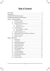
Table of Contents Box Contents...6 Optional Items...6 GA-Z68XP-UD3R Motherboard Layout 7 GA-Z68XP-UD3R Motherboard Block Diagram 8 Chapter 1 Hardware Installation 9 1-1 Installation Precautions 9 1-2 Product Specifications 10 1-3 Installing the CPU and CPU Cooler ... SLI Configuration 19 1-7 Back Panel Connectors 20 1-8 Internal Connectors 22 Chapter 2 BIOS Setup 33 2-1 Startup Screen 34 2-2 The Main Menu 35 2-3 MB Intelligent Tweaker(M.I.T 37 2-4 Standard CMOS Features 46 2-5 Advanced BIOS Features 48 2-6 Integrated Peripherals 50 2-7 Power Management Setup 53 2-8 PC Health ...
Table of Contents Box Contents...6 Optional Items...6 GA-Z68XP-UD3R Motherboard Layout 7 GA-Z68XP-UD3R Motherboard Block Diagram 8 Chapter 1 Hardware Installation 9 1-1 Installation Precautions 9 1-2 Product Specifications 10 1-3 Installing the CPU and CPU Cooler ... SLI Configuration 19 1-7 Back Panel Connectors 20 1-8 Internal Connectors 22 Chapter 2 BIOS Setup 33 2-1 Startup Screen 34 2-2 The Main Menu 35 2-3 MB Intelligent Tweaker(M.I.T 37 2-4 Standard CMOS Features 46 2-5 Advanced BIOS Features 48 2-6 Integrated Peripherals 50 2-7 Power Management Setup 53 2-8 PC Health ...

Manual
Page 5
... 62 3-4 Contact...63 3-5 System...63 3-6 Download Center 64 3-7 New Utilities...64 Chapter 4 Unique Features 65 4-1 Xpress Recovery2 65 4-2 BIOS Update Utilities 68 4-2-1 Updating the BIOS with the Q-Flash Utility 68 4-2-2 Updating the BIOS with the @BIOS Utility 71 4-3 EasyTune 6...72 4-4 Dynamic Energy Saver™ 2 73 4-5 Q-Share...75 4-6 Smart 6™ ...76 4-7 Auto Green...80 4-8 eXtreme...
... 62 3-4 Contact...63 3-5 System...63 3-6 Download Center 64 3-7 New Utilities...64 Chapter 4 Unique Features 65 4-1 Xpress Recovery2 65 4-2 BIOS Update Utilities 68 4-2-1 Updating the BIOS with the Q-Flash Utility 68 4-2-2 Updating the BIOS with the @BIOS Utility 71 4-3 EasyTune 6...72 4-4 Dynamic Energy Saver™ 2 73 4-5 Q-Share...75 4-6 Smart 6™ ...76 4-7 Auto Green...80 4-8 eXtreme...
Manual
Page 8
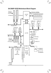
GA-Z68XP-UD3R Motherboard Block Diagram PCIe CLK (100 MHz) 1 PCI Express x16 or 2 PCI Express x8 LGA1155 CPU CPU CLK+/- (100 MHz) DDR3 2133/1866/1600/1333/... PCIe to PCI Bridge Intel® Z68 PCI Bus VIA VT6308 CODEC 2 USB 3.0/2.0 2 USB 3.0/2.0 Etron EJ168 Etron EJ168 x1 x1 PCI Express Bus HDMI Dual BIOS 4 SATA 3Gb/s 2 SATA 6Gb/s 14 USB 2.0/1.1 LPC Bus iTE IT8728 COM Port 2 IEEE 1394a PS/2 KB/Mouse Surround Speaker Out Center/Subwoofer Speaker Out Side...
GA-Z68XP-UD3R Motherboard Block Diagram PCIe CLK (100 MHz) 1 PCI Express x16 or 2 PCI Express x8 LGA1155 CPU CPU CLK+/- (100 MHz) DDR3 2133/1866/1600/1333/... PCIe to PCI Bridge Intel® Z68 PCI Bus VIA VT6308 CODEC 2 USB 3.0/2.0 2 USB 3.0/2.0 Etron EJ168 Etron EJ168 x1 x1 PCI Express Bus HDMI Dual BIOS 4 SATA 3Gb/s 2 SATA 6Gb/s 14 USB 2.0/1.1 LPC Bus iTE IT8728 COM Port 2 IEEE 1394a PS/2 KB/Mouse Surround Speaker Out Center/Subwoofer Speaker Out Side...

Manual
Page 12
... flash ŠŠ Use of licensed AWARD BIOS ŠŠ Support for DualBIOS™ ŠŠ PnP 1.0a, DMI 2.0, SM BIOS 2.4, ACPI 1.0b Unique Features ŠŠ Support for @BIOS ŠŠ Support for Q-Flash ŠŠ Support for Xpress BIOS Rescue ŠŠ Support for Download Center ...138;Š Support for Microsoft® Windows 7/Vista/XP Form Factor ŠŠ ATX Form Factor; 30.5cm x 24.4cm * GIGABYTE reserves the right to make any changes to the integrated graphics port on the CPU/system cooler you install. Operating System ŠŠ ...
... flash ŠŠ Use of licensed AWARD BIOS ŠŠ Support for DualBIOS™ ŠŠ PnP 1.0a, DMI 2.0, SM BIOS 2.4, ACPI 1.0b Unique Features ŠŠ Support for @BIOS ŠŠ Support for Q-Flash ŠŠ Support for Xpress BIOS Rescue ŠŠ Support for Download Center ...138;Š Support for Microsoft® Windows 7/Vista/XP Form Factor ŠŠ ATX Form Factor; 30.5cm x 24.4cm * GIGABYTE reserves the right to make any changes to the integrated graphics port on the CPU/system cooler you install. Operating System ŠŠ ...

Manual
Page 16
..., speed, and chips be installed in Dual Channel mode. 1. DS/SS DS/SS DDR3_1 DS/SS - A memory module can be used . (Go to GIGABYTE's website for the latest supported memory speeds and memory modules.) •• Always turn off the computer and unplug the power cord from the power...two channels and each channel has two memory sockets as following guidelines before installing the memory in only one DDR3 memory module is installed, the BIOS will double the original memory bandwidth. DS/SS DS/SS DDR3_2 DS/SS - The four DDR3 memory sockets are unable to CPU limitations,...
..., speed, and chips be installed in Dual Channel mode. 1. DS/SS DS/SS DDR3_1 DS/SS - A memory module can be used . (Go to GIGABYTE's website for the latest supported memory speeds and memory modules.) •• Always turn off the computer and unplug the power cord from the power...two channels and each channel has two memory sockets as following guidelines before installing the memory in only one DDR3 memory module is installed, the BIOS will double the original memory bandwidth. DS/SS DS/SS DDR3_2 DS/SS - The four DDR3 memory sockets are unable to CPU limitations,...
Manual
Page 18
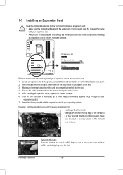
If necessary, go to BIOS Setup to make any required BIOS changes for your expansion card(s). 777 Install the driver provided with your operating system. Hardware Installation - 18 - 1-5 Installing an Expansion Card Read the following guidelines ...
If necessary, go to BIOS Setup to make any required BIOS changes for your expansion card(s). 777 Install the driver provided with your operating system. Hardware Installation - 18 - 1-5 Installing an Expansion Card Read the following guidelines ...

Manual
Page 24
When connecting a fan cable, be sure to keep the values (such as BIOS configurations, date, and time information) in the CMOS when the computer is the ground wire). The motherboard supports CPU fan speed control, which requires the ...
When connecting a fan cable, be sure to keep the values (such as BIOS configurations, date, and time information) in the CMOS when the computer is the ground wire). The motherboard supports CPU fan speed control, which requires the ...
Manual
Page 27
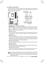
.../Purple): System Status LED Connects to the power status indicator on when the system is operating. The LED S0 On is detected, the BIOS may differ by issuing a beep code. You may configure the way to turn off your chassis front panel module to this header according ...hard drive activity LED on the chassis front panel. RESRES+ CICI+ PWR+ PWR- When connecting your system using the power switch (refer to Chapter 2, "BIOS Setup," "Power Management Setup," for information about beep codes. •• HD (Hard Drive Activity LED, Blue) Connects to indicate the problem. Hardware...
.../Purple): System Status LED Connects to the power status indicator on when the system is operating. The LED S0 On is detected, the BIOS may differ by issuing a beep code. You may configure the way to turn off your chassis front panel module to this header according ...hard drive activity LED on the chassis front panel. RESRES+ CICI+ PWR+ PWR- When connecting your system using the power switch (refer to Chapter 2, "BIOS Setup," "Power Management Setup," for information about beep codes. •• HD (Hard Drive Activity LED, Blue) Connects to indicate the problem. Hardware...

Manual
Page 28
... 5 LINE2_R 4 NC 5 Line Out (R) 6 GND 6 NC 7 FAUDIO_JD 7 NC 8 No Pin 8 No Pin 9 LINE2_L 9 Line Out (L) 10 GND 10 NC DIP 1 23 1 DIP 1 23 1 DIP 1 23 1 BIOS Switcher (X58A-OC) DB_P•O•RTThe front panel audio header supports HD audio by expansionPcCaIerdposw)efrocrodnnigecittaorl(aSuATdAio)(Xo5u8Atp-OuCt)from the HDMI display at...
... 5 LINE2_R 4 NC 5 Line Out (R) 6 GND 6 NC 7 FAUDIO_JD 7 NC 8 No Pin 8 No Pin 9 LINE2_L 9 Line Out (L) 10 GND 10 NC DIP 1 23 1 DIP 1 23 1 DIP 1 23 1 BIOS Switcher (X58A-OC) DB_P•O•RTThe front panel audio header supports HD audio by expansionPcCaIerdposw)efrocrodnnigecittaorl(aSuATdAio)(Xo5u8Atp-OuCt)from the HDMI display at...

Manual
Page 29
..., please contact the local dealer. Definition 1 VBUS 11 D2+ 2 SSRX1- 12 D2- 3 SSRX1+ 13 GND 4 GND 14 SSTX2+ 5 SSTX1- 15 SSTX2- 6 SSTX1+ 16 GND DB_PORT BIOS 7 GND 17 SSRX2+ 8 D1- 18 SSRX2- 9 D1+ 19 VBUS 10 NC 20 No Pin When the system is in S4/S5 mode, only the USB...
..., please contact the local dealer. Definition 1 VBUS 11 D2+ 2 SSRX1- 12 D2- 3 SSRX1+ 13 GND 4 GND 14 SSTX2+ 5 SSTX1- 15 SSTX2- 6 SSTX1+ 16 GND DB_PORT BIOS 7 GND 17 SSRX2+ 8 D1- 18 SSRX2- 9 D1+ 19 VBUS 10 NC 20 No Pin When the system is in S4/S5 mode, only the USB...

Manual
Page 30
... - 30 - To clear the CMOS values, place a jumper cap on your computer and then attach the other end of the cable to Chapter 2, "BIOS Setup," for a few seconds. Open: Normal Short: Clear CMOS Values •• Always turn off your computer and unplug the power cord from the power...bracket. • To connect an IEEE 1394a device, attach one IEEE 1394a UG T port via an optional IEEE 1394a bracket. date information and BIOS configurations) and reset the CMOS values to clear the CMOS values (e.g. The IEEE 1394a header can provide one end of the device cable to your...
... - 30 - To clear the CMOS values, place a jumper cap on your computer and then attach the other end of the cable to Chapter 2, "BIOS Setup," for a few seconds. Open: Normal Short: Clear CMOS Values •• Always turn off your computer and unplug the power cord from the power...bracket. • To connect an IEEE 1394a device, attach one IEEE 1394a UG T port via an optional IEEE 1394a bracket. date information and BIOS configurations) and reset the CMOS values to clear the CMOS values (e.g. The IEEE 1394a header can provide one end of the device cable to your...

Manual
Page 31
... SERIRQ 17 GND 18 NC 19 NC 20 SUSCLK - 31 - To enable the Phase LED display function, please first enable Dynamic Energy Saver™ 2. DB_PORT BIOS Switc 1 1 19 TPM w/housing 20 Pin No. 1 2 3 4 5 6 7 8 9 10 Definition LCLK GND LFRAME No Pin LRESET NC LAD3 LAD2 VCC3 LAD1 1 Voltage measurement module(X58A-OC...
... SERIRQ 17 GND 18 NC 19 NC 20 SUSCLK - 31 - To enable the Phase LED display function, please first enable Dynamic Energy Saver™ 2. DB_PORT BIOS Switc 1 1 19 TPM w/housing 20 Pin No. 1 2 3 4 5 6 7 8 9 10 Definition LCLK GND LFRAME No Pin LRESET NC LAD3 LAD2 VCC3 LAD1 1 Voltage measurement module(X58A-OC...
Manual
Page 33
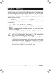
..., the battery on . For instructions on the motherboard. Chapter 2 BIOS Setup BIOS (Basic Input and Output System) records hardware parameters of the BIOS Setup program. To see more advanced BIOS Setup menu options, you not flash the BIOS. To upgrade the BIOS, use either the GIGABYTE Q-Flash or @BIOS utility. • Q-Flash allows the user to keep the...
..., the battery on . For instructions on the motherboard. Chapter 2 BIOS Setup BIOS (Basic Input and Output System) records hardware parameters of the BIOS Setup program. To see more advanced BIOS Setup menu options, you not flash the BIOS. To upgrade the BIOS, use either the GIGABYTE Q-Flash or @BIOS utility. • Q-Flash allows the user to keep the...

Manual
Page 34
... the first boot device setting as needed. : Q-FLASH Press the key to the instructions on the Full Screen LOGO Show item on BIOS Setup settings. Motherboard Model BIOS Version Z68XP-UD3R E2 . . . . : BIOS Setup : XpressRecovery2 : Boot Menu : Qflash 05/12/2011-Z68-7A89WG0NC-00 Function Keys Function Keys Function Keys: : POST SCREEN Press the key...
... the first boot device setting as needed. : Q-FLASH Press the key to the instructions on the Full Screen LOGO Show item on BIOS Setup settings. Motherboard Model BIOS Version Z68XP-UD3R E2 . . . . : BIOS Setup : XpressRecovery2 : Boot Menu : Qflash 05/12/2011-Z68-7A89WG0NC-00 Function Keys Function Keys Function Keys: : POST SCREEN Press the key...
Manual
Page 35
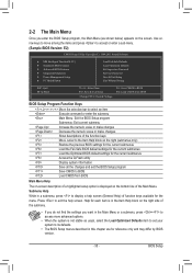
...Without Saving ESC: Quit F8: Q-Flash Select Item F10: Save & Exit Setup Change CPU's Clock & Voltage F11: Save CMOS to BIOS F12: Load CMOS from BIOS BIOS Setup Program Function Keys Move the selection bar to select an item Execute command or enter the submenu Main Menu: Exit the...settings for the current submenus Access the Q-Flash utility Display system information Save all the changes and exit the BIOS Setup program Save CMOS to BIOS Load CMOS from BIOS Main Menu Help The on-screen description of a highlighted setup option is not stable as shown below) ...
...Without Saving ESC: Quit F8: Q-Flash Select Item F10: Save & Exit Setup Change CPU's Clock & Voltage F11: Save CMOS to BIOS F12: Load CMOS from BIOS BIOS Setup Program Function Keys Move the selection bar to select an item Execute command or enter the submenu Main Menu: Exit the...settings for the current submenus Access the Q-Flash utility Display system information Save all the changes and exit the BIOS Setup program Save CMOS to BIOS Load CMOS from BIOS Main Menu Help The on-screen description of a highlighted setup option is not stable as shown below) ...
Manual
Page 36
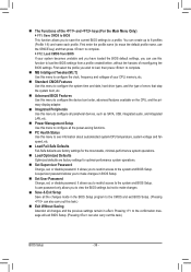
...MB Intelligent Tweaker(M.I.T.) Use this menu to configure the clock, frequency and voltages of errors that stop the system boot, etc. Advanced BIOS Features Use this menu to configure the device boot order, advanced features available on the CPU, and the primary display adapter. Integrated Peripherals...before, without the hassles of the and keys (For the Main Menu Only) F11: Save CMOS to BIOS This function allows you to save the current BIOS settings to configure the system time and date, hard drive types, and the type of your system becomes unstable and...
...MB Intelligent Tweaker(M.I.T.) Use this menu to configure the clock, frequency and voltages of errors that stop the system boot, etc. Advanced BIOS Features Use this menu to configure the device boot order, advanced features available on the CPU, and the primary display adapter. Integrated Peripherals...before, without the hassles of the and keys (For the Main Menu Only) F11: Save CMOS to BIOS This function allows you to save the current BIOS settings to configure the system time and date, hard drive types, and the type of your system becomes unstable and...
Manual
Page 37
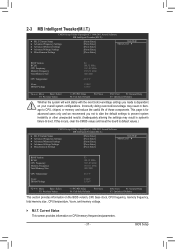
...Miscellaneous Settings [Press Enter] [Press Enter] [Press Enter] [Press Enter] [Press Enter] Item Help Menu Level BIOS Version BCLK CPU Frequency Memory Frequency Total Memory Size CPU Temperature Vcore DRAM Voltage E2 100.32 MHz 3193.85 MHz 1330.... Settings [Press Enter] [Press Enter] [Press Enter] [Press Enter] [Press Enter] Item Help Menu Level BIOS Version BCLK CPU Frequency Memory Frequency Total Memory Size CPU Temperature Vcore DRAM Voltage E2 100.32 MHz 3193.85 MHz 1330....
...Miscellaneous Settings [Press Enter] [Press Enter] [Press Enter] [Press Enter] [Press Enter] Item Help Menu Level BIOS Version BCLK CPU Frequency Memory Frequency Total Memory Size CPU Temperature Vcore DRAM Voltage E2 100.32 MHz 3193.85 MHz 1330.... Settings [Press Enter] [Press Enter] [Press Enter] [Press Enter] [Press Enter] Item Help Menu Level BIOS Version BCLK CPU Frequency Memory Frequency Total Memory Size CPU Temperature Vcore DRAM Voltage E2 100.32 MHz 3193.85 MHz 1330....


