
Manual
Page 1
...larger than 64 GB, the space beyond 64 GB can still be used for your motherboard. Enabling RAID mode in BIOS Setup: Turn on the hard disk will see shall depend on the motherboard you have installed the operating system before enabling the Smart Response Technology. 1. Set PCH... Technology utility to enable the Intel Smart Response Technology • The Intel Smart Response Technology requires a computer system with an Intel Z68 Chipset-based motherboard and an Intel Core series CPU. • The operating system must be lost once you have and the BIOS version. - 1 - The ...
...larger than 64 GB, the space beyond 64 GB can still be used for your motherboard. Enabling RAID mode in BIOS Setup: Turn on the hard disk will see shall depend on the motherboard you have installed the operating system before enabling the Smart Response Technology. 1. Set PCH... Technology utility to enable the Intel Smart Response Technology • The Intel Smart Response Technology requires a computer system with an Intel Z68 Chipset-based motherboard and an Intel Core series CPU. • The operating system must be lost once you have and the BIOS version. - 1 - The ...

Manual
Page 2
..., including the Intel Rapid Storage Technology driver. Make sure the Intel Rapid Storage Technology driver version is complete, use the "Xpress Install" function of the motherboard driver disk to enable the Intel Smart Response Technology: Step 1: After completing the steps above . 4. Installing the operating system and drivers to the SATA disk...
..., including the Intel Rapid Storage Technology driver. Make sure the Intel Rapid Storage Technology driver version is complete, use the "Xpress Install" function of the motherboard driver disk to enable the Intel Smart Response Technology: Step 1: After completing the steps above . 4. Installing the operating system and drivers to the SATA disk...

Manual
Page 2
Motherboard GA-Z68X-UD5-B3 Apr. 8, 2011 Motherboard GA-Z68X-UD5-B3 Apr. 8, 2011
Motherboard GA-Z68X-UD5-B3 Apr. 8, 2011 Motherboard GA-Z68X-UD5-B3 Apr. 8, 2011

Manual
Page 3
...respective owners. For product-related information, check on our website at: http://www.gigabyte.com Identifying Your Motherboard Revision The revision number on your motherboard revision before updating motherboard BIOS, drivers, or when looking for technical information. All rights reserved. No... transmitted, or published in any means without prior notice. Example: Check your motherboard looks like this product, GIGABYTE provides the following types of documentations: For quick set-up of the motherboard is the property of this : "REV: X.X." Copyright © 2011 GIGA...
...respective owners. For product-related information, check on our website at: http://www.gigabyte.com Identifying Your Motherboard Revision The revision number on your motherboard revision before updating motherboard BIOS, drivers, or when looking for technical information. All rights reserved. No... transmitted, or published in any means without prior notice. Example: Check your motherboard looks like this product, GIGABYTE provides the following types of documentations: For quick set-up of the motherboard is the property of this : "REV: X.X." Copyright © 2011 GIGA...

Manual
Page 4
Table of Contents Box Contents...6 Optional Items...6 GA-Z68X-UD5-B3 Motherboard Layout 7 GA-Z68X-UD5-B3 Motherboard Block Diagram 8 Chapter 1 Hardware Installation 9 1-1 Installation Precautions 9 1-2 Product Specifications 10 1-3 Installing the CPU and CPU Cooler 13 1-3-1 Installing the CPU 13 1-3-2 Installing the CPU Cooler ...
Table of Contents Box Contents...6 Optional Items...6 GA-Z68X-UD5-B3 Motherboard Layout 7 GA-Z68X-UD5-B3 Motherboard Block Diagram 8 Chapter 1 Hardware Installation 9 1-1 Installation Precautions 9 1-2 Product Specifications 10 1-3 Installing the CPU and CPU Cooler 13 1-3-1 Installing the CPU 13 1-3-2 Installing the CPU Cooler ...

Manual
Page 6
Box Contents GA-Z68X-UD5-B3 motherboard Motherboard driver disk User's Manual Quick Installation Guide Four SATA cables I/O Shield One 2-Way SLI bridge connector 3.5" Front Panel with 2 USB 3.0/2.0 ports • The box contents above are subject to change without notice. • The motherboard image is for reference only and the actual items shall depend on the product package...
Box Contents GA-Z68X-UD5-B3 motherboard Motherboard driver disk User's Manual Quick Installation Guide Four SATA cables I/O Shield One 2-Way SLI bridge connector 3.5" Front Panel with 2 USB 3.0/2.0 ports • The box contents above are subject to change without notice. • The motherboard image is for reference only and the actual items shall depend on the product package...

Manual
Page 7
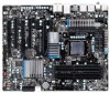
GA-Z68X-UD5-B3 Motherboard Layout KB_MS_USB SYS_FAN1 CPU_FAN R_SPDIF ATX_12V_2X USB_1394_ESATA_2 Marvell 88SE9128 USB_1394_ESATA_1 USB30 CPU_LED LGA1155 PW_SW PHASE LED PWR_FAN RST_SW CMOS_SW USB30_LAN AUDIO Realtek RTL8111E F_AUDIO VLI VL810 GD2 PCIEX1_1 (Note) PE1_LED GD1 PCIEX16 PE_LED DDR3_1 DDR3_2 DDR3_3 DDR3_4 DIMM_LED ATX BAT Renesas D720200 PCIEX1_2 CODEC SPDIF_O PCI1 GA-Z68X-UD5-B3 PCI_LED PCIe to a hardware limitation...
GA-Z68X-UD5-B3 Motherboard Layout KB_MS_USB SYS_FAN1 CPU_FAN R_SPDIF ATX_12V_2X USB_1394_ESATA_2 Marvell 88SE9128 USB_1394_ESATA_1 USB30 CPU_LED LGA1155 PW_SW PHASE LED PWR_FAN RST_SW CMOS_SW USB30_LAN AUDIO Realtek RTL8111E F_AUDIO VLI VL810 GD2 PCIEX1_1 (Note) PE1_LED GD1 PCIEX16 PE_LED DDR3_1 DDR3_2 DDR3_3 DDR3_4 DIMM_LED ATX BAT Renesas D720200 PCIEX1_2 CODEC SPDIF_O PCI1 GA-Z68X-UD5-B3 PCI_LED PCIe to a hardware limitation...

Manual
Page 8
GA-Z68X-UD5-B3 Motherboard Block Diagram 2 PCI Express x8 1 PCI Express x16 CPU CLK+/- (133 MHz) PCIe CLK or (100 MHz) LGA1155 CPU DDR3 2133/1866/1600/ 1333/1066 ...
GA-Z68X-UD5-B3 Motherboard Block Diagram 2 PCI Express x8 1 PCI Express x16 CPU CLK+/- (133 MHz) PCIe CLK or (100 MHz) LGA1155 CPU DDR3 2133/1866/1600/ 1333/1066 ...

Manual
Page 9
...; Prior to wear an electrostatic discharge (ESD) wrist strap when handling electronic com- Chapter 1 Hardware Installation 1-1 Installation Precautions The motherboard contains numerous delicate electronic circuits and components which can lead to damage to system components as well as physical harm to the user.... they are uncertain about any metal leads or connectors. •• It is best to installation, do not remove or break motherboard S/N (Serial Number) sticker or warranty sticker provided by your dealer. These stickers are required for warranty validation. •• ...
...; Prior to wear an electrostatic discharge (ESD) wrist strap when handling electronic com- Chapter 1 Hardware Installation 1-1 Installation Precautions The motherboard contains numerous delicate electronic circuits and components which can lead to damage to system components as well as physical harm to the user.... they are uncertain about any metal leads or connectors. •• It is best to installation, do not remove or break motherboard S/N (Serial Number) sticker or warranty sticker provided by your dealer. These stickers are required for warranty validation. •• ...

Manual
Page 12
...138; Support for Xpress Install ŠŠ Support for Xpress Recovery2 ŠŠ Support for EasyTune * Available functions in EasyTune may differ by motherboard model. ŠŠ Support for Dynamic Energy Saver™ 2 ŠŠ Support for Smart 6™ ŠŠ Support for Auto ...138;Š Support for Microsoft® Windows 7/Vista/XP Form Factor ŠŠ ATX Form Factor; 30.5cm x 24.4cm * GIGABYTE reserves the right to make any changes to the product specifications and product-related information without prior notice. I/O Controller ŠŠ iTE IT8728...
...138; Support for Xpress Install ŠŠ Support for Xpress Recovery2 ŠŠ Support for EasyTune * Available functions in EasyTune may differ by motherboard model. ŠŠ Support for Dynamic Energy Saver™ 2 ŠŠ Support for Smart 6™ ŠŠ Support for Auto ...138;Š Support for Microsoft® Windows 7/Vista/XP Form Factor ŠŠ ATX Form Factor; 30.5cm x 24.4cm * GIGABYTE reserves the right to make any changes to the product specifications and product-related information without prior notice. I/O Controller ŠŠ iTE IT8728...

Manual
Page 13
...your hardware specifications including the CPU, graphics card, memory, hard drive, etc. 1-3-1 Installing the CPU A. Locate the alignment keys on the motherboard CPU socket and the notches on the CPU - 13 - LGA1155 CPU Socket Alignment Key Alignment Key Pin One Corner of the CPU Socket ... latest CPU support list.) •• Always turn on the computer if the CPU cooler is not recommended that the motherboard supports the CPU. (Go to GIGABYTE's website for the peripherals. Hardware Installation It is not installed, otherwise overheating and dam- 1-3 Installing the CPU and CPU...
...your hardware specifications including the CPU, graphics card, memory, hard drive, etc. 1-3-1 Installing the CPU A. Locate the alignment keys on the motherboard CPU socket and the notches on the CPU - 13 - LGA1155 CPU Socket Alignment Key Alignment Key Pin One Corner of the CPU Socket ... latest CPU support list.) •• Always turn on the computer if the CPU cooler is not recommended that the motherboard supports the CPU. (Go to GIGABYTE's website for the peripherals. Hardware Installation It is not installed, otherwise overheating and dam- 1-3 Installing the CPU and CPU...

Manual
Page 14
... keys) and gently insert the CPU into position. Step 2: Remove the CPU socket cover as well. Step 5: Push the CPU socket lever back into the motherboard CPU socket. Hardware Installation - 14 - When replacing the load plate, make sure to the "REMOVE" mark) and then remove the cover. (DO NOT touch socket...
... keys) and gently insert the CPU into position. Step 2: Remove the CPU socket cover as well. Step 5: Push the CPU socket lever back into the motherboard CPU socket. Hardware Installation - 14 - When replacing the load plate, make sure to the "REMOVE" mark) and then remove the cover. (DO NOT touch socket...

Manual
Page 15
... an even and thin layer of thermal grease on the surface of the CPU cooler to your CPU cooler installation manual for instructions on the motherboard. Check that the Male and Female push pins are joined closely. (Refer to the CPU fan header (CPU_FAN) on the push pins diagonally. ...Hardware Installation Push down each push pin. Step 4: You should hear a "click" when pushing down on the motherboard. Use extreme care when removing the CPU cooler because the thermal grease/tape between the CPU cooler and CPU may damage the CPU. - 15 - Step...
... an even and thin layer of thermal grease on the surface of the CPU cooler to your CPU cooler installation manual for instructions on the motherboard. Check that the Male and Female push pins are joined closely. (Refer to the CPU fan header (CPU_FAN) on the push pins diagonally. ...Hardware Installation Push down each push pin. Step 4: You should hear a "click" when pushing down on the motherboard. Use extreme care when removing the CPU cooler because the thermal grease/tape between the CPU cooler and CPU may damage the CPU. - 15 - Step...

Manual
Page 16
... (SS=Single-Sided, DS=Double-Sided, "- -"=No Memory) DDR3_1 DDR3_2 DDR3_3 DDR3_4 Due to insert the memory, switch the direction. 1-4-1 Dual Channel Memory Configuration This motherboard provides four DDR3 memory sockets and supports Dual Channel Technology. The four DDR3 memory sockets are unable to CPU limitations, read the following : Channel A: DDR3_1... When enabling Dual Channel mode with two memory modules, we recommend that memory of the same capacity, brand, speed, and chips be used. (Go to GIGABYTE's website for optimum performance. DS/SS DS/SS DDR3_3 DS/SS -
... (SS=Single-Sided, DS=Double-Sided, "- -"=No Memory) DDR3_1 DDR3_2 DDR3_3 DDR3_4 Due to insert the memory, switch the direction. 1-4-1 Dual Channel Memory Configuration This motherboard provides four DDR3 memory sockets and supports Dual Channel Technology. The four DDR3 memory sockets are unable to CPU limitations, read the following : Channel A: DDR3_1... When enabling Dual Channel mode with two memory modules, we recommend that memory of the same capacity, brand, speed, and chips be used. (Go to GIGABYTE's website for optimum performance. DS/SS DS/SS DDR3_3 DS/SS -

Manual
Page 17
.... Step 1: Note the orientation of the memory socket. Spread the retaining clips at both ends of the memory module. Place the memory module on this motherboard. DDR3 and DDR2 DIMMs are not compatible to each other or DDR DIMMs. Be sure to the memory module. As indicated in the picture on...
.... Step 1: Note the orientation of the memory socket. Spread the retaining clips at both ends of the memory module. Place the memory module on this motherboard. DDR3 and DDR2 DIMMs are not compatible to each other or DDR DIMMs. Be sure to the memory module. As indicated in the picture on...

Manual
Page 18
... and does not rock. • Removing the Card from the power outlet before you begin to install an expansion card: •• Make sure the motherboard supports the expansion card. Secure the card's metal bracket to the chassis back panel with the slot, and press down on the card until it...
... and does not rock. • Removing the Card from the power outlet before you begin to install an expansion card: •• Make sure the motherboard supports the expansion card. Secure the card's metal bracket to the chassis back panel with the slot, and press down on the card until it...

Manual
Page 19
... PCIEX8 slots. To Enable SLI Function After installing the graphics card driver in the operating system, go to the Catalyst Control Center. A CrossFireX/SLI-supported motherboard with your graphics cards for enabling CrossFireX/SLI technology may be needed or not depending on the PCIEX16 slot. C. To Enable CrossFireX Function After installing...
... PCIEX8 slots. To Enable SLI Function After installing the graphics card driver in the operating system, go to the Catalyst Control Center. A CrossFireX/SLI-supported motherboard with your graphics cards for enabling CrossFireX/SLI technology may be needed or not depending on the PCIEX16 slot. C. To Enable CrossFireX Function After installing...

Manual
Page 20
..., ensure that your audio system provides an optical digital audio in connector. Use this feature, ensure that your device and then remove it from the motherboard. •• When removing the cable, pull it side to side to an external audio system that supports digital optical audio. eSATA/USB Combo Connector...
..., ensure that your audio system provides an optical digital audio in connector. Use this feature, ensure that your device and then remove it from the motherboard. •• When removing the cable, pull it side to side to an external audio system that supports digital optical audio. eSATA/USB Combo Connector...

Manual
Page 22
... the CPU VTT. the yellow LEDs will light up under normal working conditions (green LED) GD2: Excessive overvoltage or overloading (yellow LED) Diagnostic LEDs This motherboard has 6 onboard LEDs controlled by the system BIOS to improper plug/unplug actions. The 6 LEDs indicate if a component (including CPU and memory) or a device (...when the components/devices have a problem. ACPI LEDs: S4_S5_LED S3_LED S1_LED S0_LED Hardware Installation - 22 - 1-8 Onboard LEDs and Switches CPU VTT Phase Indicator LEDs This motherboard contains 2 phase indicator LEDs controlled by the system BIOS.
... the CPU VTT. the yellow LEDs will light up under normal working conditions (green LED) GD2: Excessive overvoltage or overloading (yellow LED) Diagnostic LEDs This motherboard has 6 onboard LEDs controlled by the system BIOS to improper plug/unplug actions. The 6 LEDs indicate if a component (including CPU and memory) or a device (...when the components/devices have a problem. ACPI LEDs: S4_S5_LED S3_LED S1_LED S0_LED Hardware Installation - 22 - 1-8 Onboard LEDs and Switches CPU VTT Phase Indicator LEDs This motherboard contains 2 phase indicator LEDs controlled by the system BIOS.
Manual
Page 23
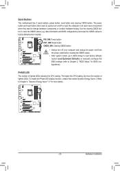
... the CPU loading, the more details. - 23 - date information and BIOS configurations) and reset the CMOS values to factory defaults when needed. Quick Buttons This motherboard has 3 quick buttons: power button, reset button and clearing CMOS button.
... the CPU loading, the more details. - 23 - date information and BIOS configurations) and reset the CMOS values to factory defaults when needed. Quick Buttons This motherboard has 3 quick buttons: power button, reset button and clearing CMOS button.


