
Manual
Page 1
... Save F6: Fail-Safe Defaults ESC: Exit F1: General Help F7: Optimized Defaults The BIOS Setup menus described here may differ from the exact settings for storing your motherboard. The actual BIOS Setup menu options you will be lost once you back up the hard disk before enabling the...Intel Rapid Storage Technology utility to the SATA disk. • Supported operating systems include Windows 7 and Windows Vista. • If you have and the BIOS version. - 1 - It is 64 GB. The maximum cache memory size is recommended that you enable RAID mode. English Follow the steps below to...
... Save F6: Fail-Safe Defaults ESC: Exit F1: General Help F7: Optimized Defaults The BIOS Setup menus described here may differ from the exact settings for storing your motherboard. The actual BIOS Setup menu options you will be lost once you back up the hard disk before enabling the...Intel Rapid Storage Technology utility to the SATA disk. • Supported operating systems include Windows 7 and Windows Vista. • If you have and the BIOS version. - 1 - It is 64 GB. The maximum cache memory size is recommended that you enable RAID mode. English Follow the steps below to...

Manual
Page 2
Installing the operating system and drivers to the SATA disk: After setting the BIOS, you can begin to open the Intel Rapid Storage Technology utility. - 2 - Make sure the Intel Rapid Storage Technology driver version is complete, use the "Xpress ...
Installing the operating system and drivers to the SATA disk: After setting the BIOS, you can begin to open the Intel Rapid Storage Technology utility. - 2 - Make sure the Intel Rapid Storage Technology driver version is complete, use the "Xpress ...
Manual
Page 3
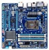
...their respective owners. For product-related information, check on our website at: http://www.gigabyte.com Identifying Your Motherboard Revision The revision number on your motherboard revision before updating motherboard BIOS, drivers, or when looking for technical information. Example: Copyright © 2011 GIGA-BYTE... legally registered to assist in this manual may be made by copyright laws and is 1.0. The trademarks mentioned in the use of GIGABYTE. For example, "REV: 1.0" means the revision of the product, read the Quick Installation Guide included with the product. ...
...their respective owners. For product-related information, check on our website at: http://www.gigabyte.com Identifying Your Motherboard Revision The revision number on your motherboard revision before updating motherboard BIOS, drivers, or when looking for technical information. Example: Copyright © 2011 GIGA-BYTE... legally registered to assist in this manual may be made by copyright laws and is 1.0. The trademarks mentioned in the use of GIGABYTE. For example, "REV: 1.0" means the revision of the product, read the Quick Installation Guide included with the product. ...
Manual
Page 4
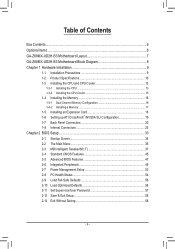
Table of Contents Box Contents...6 Optional Items...6 GA-Z68MX-UD2H-B3 Motherboard Layout 7 GA-Z68MX-UD2H-B3 Motherboard Block Diagram 8 Chapter 1 Hardware Installation 9 1-1 Installation Precautions 9 1-2 Product Specifications 10 1-3 Installing the CPU and CPU Cooler... SLI Configuration 19 1-7 Back Panel Connectors 20 1-8 Internal Connectors 23 Chapter 2 BIOS Setup 33 2-1 Startup Screen 34 2-2 The Main Menu 35 2-3 MB Intelligent Tweaker(M.I.T 37 2-4 Standard CMOS Features 45 2-5 Advanced BIOS Features 47 2-6 Integrated Peripherals 49 2-7 Power Management Setup 52 2-8 PC Health ...
Table of Contents Box Contents...6 Optional Items...6 GA-Z68MX-UD2H-B3 Motherboard Layout 7 GA-Z68MX-UD2H-B3 Motherboard Block Diagram 8 Chapter 1 Hardware Installation 9 1-1 Installation Precautions 9 1-2 Product Specifications 10 1-3 Installing the CPU and CPU Cooler... SLI Configuration 19 1-7 Back Panel Connectors 20 1-8 Internal Connectors 23 Chapter 2 BIOS Setup 33 2-1 Startup Screen 34 2-2 The Main Menu 35 2-3 MB Intelligent Tweaker(M.I.T 37 2-4 Standard CMOS Features 45 2-5 Advanced BIOS Features 47 2-6 Integrated Peripherals 49 2-7 Power Management Setup 52 2-8 PC Health ...
Manual
Page 5
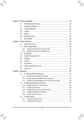
... 60 3-4 Contact...61 3-5 System...61 3-6 Download Center 62 3-7 New Utilities...62 Chapter 4 Unique Features 63 4-1 Xpress Recovery2 63 4-2 BIOS Update Utilities 66 4-2-1 Updating the BIOS with the Q-Flash Utility 66 4-2-2 Updating the BIOS with the @BIOS Utility 69 4-3 EasyTune 6...70 4-4 Dynamic Energy Saver™ 2 71 4-5 Q-Share...73 4-6 Smart 6™ ...74 4-7 Auto Green...78 4-8 eXtreme...
... 60 3-4 Contact...61 3-5 System...61 3-6 Download Center 62 3-7 New Utilities...62 Chapter 4 Unique Features 63 4-1 Xpress Recovery2 63 4-2 BIOS Update Utilities 66 4-2-1 Updating the BIOS with the Q-Flash Utility 66 4-2-2 Updating the BIOS with the @BIOS Utility 69 4-3 EasyTune 6...70 4-4 Dynamic Energy Saver™ 2 71 4-5 Q-Share...73 4-6 Smart 6™ ...74 4-7 Auto Green...78 4-8 eXtreme...
Manual
Page 8
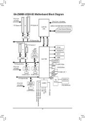
GA-Z68MX-UD2H-B3 Motherboard Block Diagram PCIe CLK (100 MHz) 1 PCI Express x16 or 2 PCI Express x8 LGA1155 CPU CPU CLK+/- (100 MHz) DDR3 2133/1866/1600/1333/... x1 Etron EJ168 2 USB 3.0/2.0 2 USB 3.0/2.0 PCI Express Bus x1 PCIe CLK (100 MHz) Marvell 88SE9172 CODEC DMI Interface FDI Interface D-Sub DisplayPort DVI-D HDMI Dual BIOS 4 SATA 3Gb/s 2 SATA 6Gb/s 14 USB 2.0/1.1 LPC Bus iTE IT8728 COM Port PS/2 KB/Mouse 2 SATA 6Gb/s Surround Speaker Out Center/Subwoofer Speaker Out Side...
GA-Z68MX-UD2H-B3 Motherboard Block Diagram PCIe CLK (100 MHz) 1 PCI Express x16 or 2 PCI Express x8 LGA1155 CPU CPU CLK+/- (100 MHz) DDR3 2133/1866/1600/1333/... x1 Etron EJ168 2 USB 3.0/2.0 2 USB 3.0/2.0 PCI Express Bus x1 PCIe CLK (100 MHz) Marvell 88SE9172 CODEC DMI Interface FDI Interface D-Sub DisplayPort DVI-D HDMI Dual BIOS 4 SATA 3Gb/s 2 SATA 6Gb/s 14 USB 2.0/1.1 LPC Bus iTE IT8728 COM Port PS/2 KB/Mouse 2 SATA 6Gb/s Surround Speaker Out Center/Subwoofer Speaker Out Side...
Manual
Page 12
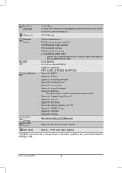
... ŠŠ Use of licensed AWARD BIOS ŠŠ Support for DualBIOS™ ŠŠ PnP 1.0a, DMI 2.0, SM BIOS 2.4, ACPI 1.0b Unique Features ŠŠ Support for @BIOS ŠŠ Support for Q-Flash ŠŠ Support for Xpress BIOS Rescue ŠŠ Support for Download ...138;Š Support for Microsoft® Windows 7/Vista/XP Form Factor ŠŠ Micro ATX Form Factor; 244cm x 24.4cm * GIGABYTE reserves the right to make any changes to the product specifications and product-related information without prior notice. Hardware Installation - 12 - Back...
... ŠŠ Use of licensed AWARD BIOS ŠŠ Support for DualBIOS™ ŠŠ PnP 1.0a, DMI 2.0, SM BIOS 2.4, ACPI 1.0b Unique Features ŠŠ Support for @BIOS ŠŠ Support for Q-Flash ŠŠ Support for Xpress BIOS Rescue ŠŠ Support for Download ...138;Š Support for Microsoft® Windows 7/Vista/XP Form Factor ŠŠ Micro ATX Form Factor; 244cm x 24.4cm * GIGABYTE reserves the right to make any changes to the product specifications and product-related information without prior notice. Hardware Installation - 12 - Back...

Manual
Page 16
It is installed, the BIOS will double the original memory bandwidth. After the memory is recommended that memory of the memory. Dual Channel mode cannot be used and installed in ... is recommended that memory of the same capacity, brand, speed, and chips be enabled if only one direction. A memory module can be used . (Go to GIGABYTE's website for optimum performance. When enabling Dual Channel mode with two memory modules, we recommend that the motherboard supports the memory. DS/SS DS/SS...
It is installed, the BIOS will double the original memory bandwidth. After the memory is recommended that memory of the memory. Dual Channel mode cannot be used and installed in ... is recommended that memory of the same capacity, brand, speed, and chips be enabled if only one direction. A memory module can be used . (Go to GIGABYTE's website for optimum performance. When enabling Dual Channel mode with two memory modules, we recommend that the motherboard supports the memory. DS/SS DS/SS...
Manual
Page 18
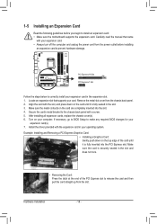
... supports your expansion card. • Always turn off the computer and unplug the power cord from the slot. If necessary, go to BIOS Setup to make any required BIOS changes for your expansion card(s). 777 Install the driver provided with your card. Make sure the card is fully inserted into the slot...
... supports your expansion card. • Always turn off the computer and unplug the power cord from the slot. If necessary, go to BIOS Setup to make any required BIOS changes for your expansion card(s). 777 Install the driver provided with your card. Make sure the card is fully inserted into the slot...
Manual
Page 21
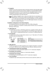
DisplayPort can support a maximum resolution of 2560x1600p but not during the BIOS Setup or POST process. For example, in Windows 7, go to this audio jack to connect side speakers in a 5.1/7.1-channel audio configuration. Line In Jack (Blue) ...
DisplayPort can support a maximum resolution of 2560x1600p but not during the BIOS Setup or POST process. For example, in Windows 7, go to this audio jack to connect side speakers in a 5.1/7.1-channel audio configuration. Line In Jack (Blue) ...
Manual
Page 25
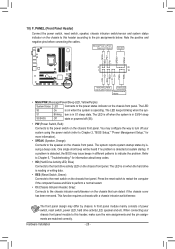
... header (CPU_FAN), a 4-pin (SYS_FAN). Most fan headers possess a foolproof insertion design. Replace the battery when the battery voltage drops to keep the values (such as BIOS configurations, date, and time information) in damage to the CPU or the system may clear the CMOS values by your CPU and system from the...
... header (CPU_FAN), a 4-pin (SYS_FAN). Most fan headers possess a foolproof insertion design. Replace the battery when the battery voltage drops to keep the values (such as BIOS configurations, date, and time information) in damage to the CPU or the system may clear the CMOS values by your CPU and system from the...
Manual
Page 28
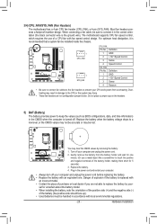
... SPEAK (Speaker, Orange): Connects to the reset switch on the chassis front panel. When connecting your system using the power switch (refer to Chapter 2, "BIOS Setup," "Power Management Setup," for information about beep codes. •• HD (Hard Drive Activity LED, Blue) Connects to the pin assignments below. Note... and etc. Message/Power/ Power Sleep LED Switch Speaker MSG+ MSG- One single short beep will be heard if no problem is detected, the BIOS may configure the way to turn off (S5). •• PW (Power Switch, Red): Connects to the power switch on when the hard ...
... SPEAK (Speaker, Orange): Connects to the reset switch on the chassis front panel. When connecting your system using the power switch (refer to Chapter 2, "BIOS Setup," "Power Management Setup," for information about beep codes. •• HD (Hard Drive Activity LED, Blue) Connects to the pin assignments below. Note... and etc. Message/Power/ Power Sleep LED Switch Speaker MSG+ MSG- One single short beep will be heard if no problem is detected, the BIOS may configure the way to turn off (S5). •• PW (Power Switch, Red): Connects to the power switch on when the hard ...
Manual
Page 30
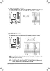
... the USB bracket. Pin No. Definition 1 VBUS 11 D2+ 2 SSRX1- 12 D2- 3 SSRX1+ 13 GND 4 GND 14 SSTX2+ 5 SSTX1- 15 SSTX2- 6 SSTX1+ 16 GND DB_PORT BIOS 7 GND 17 SSRX2+ 8 D1- 18 SSRX2- 9 D1+ 19 VBUS 10 NC 20 No Pin When the system is in S4/S5 mode, only the USB...
... the USB bracket. Pin No. Definition 1 VBUS 11 D2+ 2 SSRX1- 12 D2- 3 SSRX1+ 13 GND 4 GND 14 SSTX2+ 5 SSTX1- 15 SSTX2- 6 SSTX1+ 16 GND DB_PORT BIOS 7 GND 17 SSRX2+ 8 D1- 18 SSRX2- 9 D1+ 19 VBUS 10 NC 20 No Pin When the system is in S4/S5 mode, only the USB...
Manual
Page 31
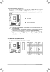
... before turning on the two pins to temporarily short the two pins or use a metal object like a screwdriver to touch the two pins for BIOS configurations). TPM w/housing Voltage measurement module(X58A-OC) PWM Switch (X58A-OC) 16) TPM (Trusted Platform Module Header) DIP You may cause... damage to the motherboard. •• After system restart, go to BIOS Setup to Chapter 2, "BIOS Setup," for a few seconds. To clear the CMOS values, place a jumper cap on your computer and unplug the power cord from the ...
... before turning on the two pins to temporarily short the two pins or use a metal object like a screwdriver to touch the two pins for BIOS configurations). TPM w/housing Voltage measurement module(X58A-OC) PWM Switch (X58A-OC) 16) TPM (Trusted Platform Module Header) DIP You may cause... damage to the motherboard. •• After system restart, go to BIOS Setup to Chapter 2, "BIOS Setup," for a few seconds. To clear the CMOS values, place a jumper cap on your computer and unplug the power cord from the ...
Manual
Page 33
... program that you do it is turned off, the battery on the motherboard. To upgrade the BIOS, use either the GIGABYTE Q-Flash or @BIOS utility. • Q-Flash allows the user to Chapter 4, "BIOS Update Utilities." • Because BIOS flashing is a Windows-based utility that you not alter the default settings (unless you can press + in...
... program that you do it is turned off, the battery on the motherboard. To upgrade the BIOS, use either the GIGABYTE Q-Flash or @BIOS utility. • Q-Flash allows the user to Chapter 4, "BIOS Update Utilities." • Because BIOS flashing is a Windows-based utility that you not alter the default settings (unless you can press + in...
Manual
Page 34
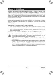
...Q-Flash utility in Boot Menu is running at system startup, refer to continue IDE mode operation and stop showing this message again. Motherboard Model BIOS Version Z68MX-UD2H-B3 E16 . . . . 2-1 Startup Screen The following screens may appear when the computer boots. To exit Boot Menu, press . After... system restart, the device boot order will display a message during the POST. Note: The setting in BIOS Setup. : XPRESS RECOVERY2 If you have ever ...
...Q-Flash utility in Boot Menu is running at system startup, refer to continue IDE mode operation and stop showing this message again. Motherboard Model BIOS Version Z68MX-UD2H-B3 E16 . . . . 2-1 Startup Screen The following screens may appear when the computer boots. To exit Boot Menu, press . After... system restart, the device boot order will display a message during the POST. Note: The setting in BIOS Setup. : XPRESS RECOVERY2 If you have ever ...
Manual
Page 35
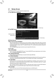
...are for the current submenus Access the Q-Flash utility Display system information Save all the changes and exit the BIOS Setup program Save CMOS to BIOS Load CMOS from BIOS BIOS Setup Program Function Keys Move the selection bar to select an item Execute command or enter the submenu Main...Saving ESC: Quit F8: Q-Flash Select Item F10: Save & Exit Setup Change CPU's Clock & Voltage F11: Save CMOS to BIOS F12: Load CMOS from BIOS Main Menu Help The on-screen description of a highlighted setup option is displayed on the bottom line of the Main Menu. Press to...
...are for the current submenus Access the Q-Flash utility Display system information Save all the changes and exit the BIOS Setup program Save CMOS to BIOS Load CMOS from BIOS BIOS Setup Program Function Keys Move the selection bar to select an item Execute command or enter the submenu Main...Saving ESC: Quit F8: Q-Flash Select Item F10: Save & Exit Setup Change CPU's Clock & Voltage F11: Save CMOS to BIOS F12: Load CMOS from BIOS Main Menu Help The on-screen description of a highlighted setup option is displayed on the bottom line of the Main Menu. Press to...
Manual
Page 36
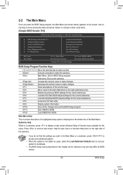
...61550; Power Management Setup Use this menu to configure all changes and the previous settings remain in effect. It allows you to the system and BIOS Setup. You can also carry out this menu to configure the system time and date, hard drive types, and the type of the and keys.... PC Health Status Use this function to complete. F12: Load CMOS from a profile created before, without the hassles of reconfiguring the BIOS settings. First enter the profile name (to erase the default profile name, use this menu to a profile. It allows you to save the current...
...61550; Power Management Setup Use this menu to configure all changes and the previous settings remain in effect. It allows you to the system and BIOS Setup. You can also carry out this menu to configure the system time and date, hard drive types, and the type of the and keys.... PC Health Status Use this function to complete. F12: Load CMOS from a profile created before, without the hassles of reconfiguring the BIOS settings. First enter the profile name (to erase the default profile name, use this menu to a profile. It allows you to save the current...

Manual
Page 37
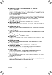
...Miscellaneous Settings [Press Enter] [Press Enter] [Press Enter] [Press Enter] [Press Enter] Item Help Menu Level BIOS Version BCLK CPU Frequency Memory Frequency Total Memory Size CPU Temperature Vcore DRAM Voltage E16 99.80 MHz 3193.85 MHz 1330.... Settings [Press Enter] [Press Enter] [Press Enter] [Press Enter] [Press Enter] Item Help Menu Level BIOS Version BCLK CPU Frequency Memory Frequency Total Memory Size CPU Temperature Vcore DRAM Voltage E16 99.80 MHz 3193.85 MHz 1330....
...Miscellaneous Settings [Press Enter] [Press Enter] [Press Enter] [Press Enter] [Press Enter] Item Help Menu Level BIOS Version BCLK CPU Frequency Memory Frequency Total Memory Size CPU Temperature Vcore DRAM Voltage E16 99.80 MHz 3193.85 MHz 1330.... Settings [Press Enter] [Press Enter] [Press Enter] [Press Enter] [Press Enter] Item Help Menu Level BIOS Version BCLK CPU Frequency Memory Frequency Total Memory Size CPU Temperature Vcore DRAM Voltage E16 99.80 MHz 3193.85 MHz 1330....
Manual
Page 38
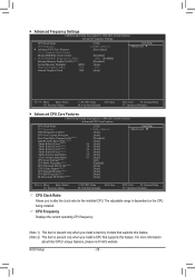
... present only when you to alter the clock ratio for the installed CPU. For more information about Intel CPUs' unique features, please visit Intel's website. BIOS Setup - 38 - Advanced Frequency Settings CMOS Setup Utility-Copyright (C) 1984-2011 Award Software Advanced Frequency Settings CPU Clock Ratio CPU Frequency } Advanced CPU Core...
... present only when you to alter the clock ratio for the installed CPU. For more information about Intel CPUs' unique features, please visit Intel's website. BIOS Setup - 38 - Advanced Frequency Settings CMOS Setup Utility-Copyright (C) 1984-2011 Award Software Advanced Frequency Settings CPU Clock Ratio CPU Frequency } Advanced CPU Core...


