
Manual
Page 1
...ESC: Exit F1: General Help F7: Optimized Defaults The BIOS Setup menus described here may differ from the exact settings for storing your motherboard. It is 64 GB. Launching the Intel Rapid Storage Technology utility to enable the Intel Smart Response Technology • The Intel Smart ...Response Technology requires a computer system with an Intel Z68 Chipset-based motherboard and an Intel Core series CPU. • The operating system must be installed to RAID(XHD). The actual BIOS Setup menu options ...
...ESC: Exit F1: General Help F7: Optimized Defaults The BIOS Setup menus described here may differ from the exact settings for storing your motherboard. It is 64 GB. Launching the Intel Rapid Storage Technology utility to enable the Intel Smart Response Technology • The Intel Smart ...Response Technology requires a computer system with an Intel Z68 Chipset-based motherboard and an Intel Core series CPU. • The operating system must be installed to RAID(XHD). The actual BIOS Setup menu options ...

Manual
Page 2
... install the operating system. English 3. Installing the operating system and drivers to the SATA disk: After setting the BIOS, you can begin to install all motherboard drivers, including the Intel Rapid Storage Technology driver. After the installation is 10.5 or above and restarting your system, find the IRST icon in...
... install the operating system. English 3. Installing the operating system and drivers to the SATA disk: After setting the BIOS, you can begin to install all motherboard drivers, including the Intel Rapid Storage Technology driver. After the installation is 10.5 or above and restarting your system, find the IRST icon in...
Manual
Page 2
Motherboard GA-Z68M-D2H Jun. 10, 2011 Motherboard GA-Z68M-D2H Jun. 10, 2011
Motherboard GA-Z68M-D2H Jun. 10, 2011 Motherboard GA-Z68M-D2H Jun. 10, 2011
Manual
Page 3
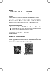
... the product, read the Quick Installation Guide included with the product. For detailed product information, carefully read the User's Manual. No part of GIGABYTE. Check your motherboard looks like this manual are legally registered to their respective owners. Changes to assist in this : "REV: X.X." Documentation Classifications In order to the specifications...
... the product, read the Quick Installation Guide included with the product. For detailed product information, carefully read the User's Manual. No part of GIGABYTE. Check your motherboard looks like this manual are legally registered to their respective owners. Changes to assist in this : "REV: X.X." Documentation Classifications In order to the specifications...
Manual
Page 4
Table of Contents Box Contents...6 Optional Items...6 GA-Z68M-D2H Motherboard Layout 7 GA-Z68M-D2H Motherboard Block Diagram 8 Chapter 1 Hardware Installation 9 1-1 Installation Precautions 9 1-2 Product Specifications 10 1-3 Installing the CPU and CPU Cooler 13 1-3-1 Installing the CPU 13 1-3-2 Installing the CPU Cooler ...
Table of Contents Box Contents...6 Optional Items...6 GA-Z68M-D2H Motherboard Layout 7 GA-Z68M-D2H Motherboard Block Diagram 8 Chapter 1 Hardware Installation 9 1-1 Installation Precautions 9 1-2 Product Specifications 10 1-3 Installing the CPU and CPU Cooler 13 1-3-1 Installing the CPU 13 1-3-2 Installing the CPU Cooler ...
Manual
Page 6
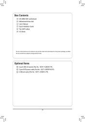
Box Contents GA-Z68M-D2H motherboard Motherboard driver disk User's Manual Quick Installation Guide Two SATA cables I/O Shield The box contents above are subject to change without notice. Optional Items 2-port USB 2.0 bracket (Part No. 12CR1-1UB030-5*R) 2-port SATA power cable (Part No. 12CF1-2SERPW-0*R) COM port cable (Part No. 12CF1-1CM001-3*R) - 6 - The box contents are for reference only and the actual items shall depend on the product package you obtain.
Box Contents GA-Z68M-D2H motherboard Motherboard driver disk User's Manual Quick Installation Guide Two SATA cables I/O Shield The box contents above are subject to change without notice. Optional Items 2-port USB 2.0 bracket (Part No. 12CR1-1UB030-5*R) 2-port SATA power cable (Part No. 12CF1-2SERPW-0*R) COM port cable (Part No. 12CF1-1CM001-3*R) - 6 - The box contents are for reference only and the actual items shall depend on the product package you obtain.
Manual
Page 7
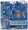
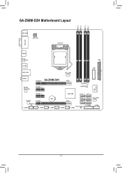
GA-Z68M-D2H Motherboard Layout DDR3_4 DDR3_2 DDR3_3 DDR3_1 KB_USB ATX_12V LGA1155 VGA_DVI HDMI OPTICAL R_USB USB_LAN CPU_FAN ATX TPM AUDIO Realtek RTL8111E PCIEX16 GA-Z68M-D2H PCIEX1_1 B_BIOS M_BIOS iTE IT8728 PCIEX1_2 CODEC PCIEX4 SPDIF_O F_AUDIO F_USB4 BAT F_USB3 F_USB2 Intel® Z68 SATA3_0 SATA3_1 SATA2_2 SATA2_3 SYS_FAN SATA2_4 SATA2_5 F_PANEL COM CLR_CMOS F_USB1 - 7 -
GA-Z68M-D2H Motherboard Layout DDR3_4 DDR3_2 DDR3_3 DDR3_1 KB_USB ATX_12V LGA1155 VGA_DVI HDMI OPTICAL R_USB USB_LAN CPU_FAN ATX TPM AUDIO Realtek RTL8111E PCIEX16 GA-Z68M-D2H PCIEX1_1 B_BIOS M_BIOS iTE IT8728 PCIEX1_2 CODEC PCIEX4 SPDIF_O F_AUDIO F_USB4 BAT F_USB3 F_USB2 Intel® Z68 SATA3_0 SATA3_1 SATA2_2 SATA2_3 SYS_FAN SATA2_4 SATA2_5 F_PANEL COM CLR_CMOS F_USB1 - 7 -
Manual
Page 8
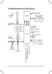
GA-Z68M-D2H Motherboard Block Diagram 1 PCI Express x16 PCIe CLK (100 MHz) LGA1155 CPU CPU CLK+/- (100 MHz) DDR3 2133/1866/1600/ 1333/1066 MHz Dual Channel Memory DMI 2.0 FDI PCI Express Bus x16 D-Sub DVI-D HDMI PCIe CLK (100 MHz) LAN RJ45 Realtek RTL8111E x1 PCI Express Bus x1 x4 2 PCI Express x1 1 PCI Express x4 Intel® Z68 Dual BIOS 2 SATA 6Gb/s 4 SATA 3Gb/s 14 USB 2.0/1.1 CODEC LPC Bus iTE IT8728 COM Port PS/2 KB/Mouse MIC (Center/Subwoofer Speaker Out) Line Out (Front Speaker Out) Line In (Rear Speaker Out) S/PDIF Out - 8 -
GA-Z68M-D2H Motherboard Block Diagram 1 PCI Express x16 PCIe CLK (100 MHz) LGA1155 CPU CPU CLK+/- (100 MHz) DDR3 2133/1866/1600/ 1333/1066 MHz Dual Channel Memory DMI 2.0 FDI PCI Express Bus x16 D-Sub DVI-D HDMI PCIe CLK (100 MHz) LAN RJ45 Realtek RTL8111E x1 PCI Express Bus x1 x4 2 PCI Express x1 1 PCI Express x4 Intel® Z68 Dual BIOS 2 SATA 6Gb/s 4 SATA 3Gb/s 14 USB 2.0/1.1 CODEC LPC Bus iTE IT8728 COM Port PS/2 KB/Mouse MIC (Center/Subwoofer Speaker Out) Line Out (Front Speaker Out) Line In (Rear Speaker Out) S/PDIF Out - 8 -
Manual
Page 9
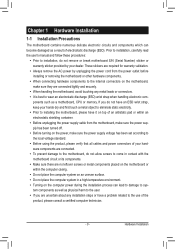
...the product, please consult a certified computer technician. - 9 - If you are connected tightly and securely. •• When handling the motherboard, avoid touching any metal leads or connectors. •• It is best to the use of electrostatic discharge (ESD). Chapter 1 Hardware Installation... shielding container. •• Before unplugging the power supply cable from the power outlet before installing or removing the motherboard or other hardware components. •• When connecting hardware components to the internal connectors on the computer power during...
...the product, please consult a certified computer technician. - 9 - If you are connected tightly and securely. •• When handling the motherboard, avoid touching any metal leads or connectors. •• It is best to the use of electrostatic discharge (ESD). Chapter 1 Hardware Installation... shielding container. •• Before unplugging the power supply cable from the power outlet before installing or removing the motherboard or other hardware components. •• When connecting hardware components to the internal connectors on the computer power during...
Manual
Page 12
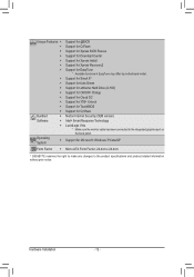
...138; Support for Xpress Install ŠŠ Support for Xpress Recovery2 ŠŠ Support for EasyTune * Available functions in EasyTune may differ by motherboard model. ŠŠ Support for Smart 6™ ŠŠ Support for Auto Green ŠŠ Support for eXtreme Hard Drive (X.H.D) &#...;Š Support for Microsoft® Windows 7/Vista/XP Form Factor ŠŠ Micro ATX Form Factor; 24.4cm x 24.4cm * GIGABYTE reserves the right to make any changes to the integrated graphics port on the back panel. Hardware Installation - 12 - Operating System ŠŠ...
...138; Support for Xpress Install ŠŠ Support for Xpress Recovery2 ŠŠ Support for EasyTune * Available functions in EasyTune may differ by motherboard model. ŠŠ Support for Smart 6™ ŠŠ Support for Auto Green ŠŠ Support for eXtreme Hard Drive (X.H.D) &#...;Š Support for Microsoft® Windows 7/Vista/XP Form Factor ŠŠ Micro ATX Form Factor; 24.4cm x 24.4cm * GIGABYTE reserves the right to make any changes to the integrated graphics port on the back panel. Hardware Installation - 12 - Operating System ŠŠ...
Manual
Page 13
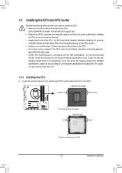
...surface of the CPU. •• Do not turn on the computer if the CPU cooler is not recommended that the motherboard supports the CPU. (Go to GIGABYTE's website for the peripherals. The CPU cannot be set the frequency beyond hardware specifications since it does not meet the standard .... (Or you may occur. •• Set the CPU host frequency in accordance with the CPU specifications. Locate the alignment keys on the motherboard CPU socket and the notches on the CPU - 13 - 1-3 Installing the CPU and CPU Cooler Read the following guidelines before installing the CPU ...
...surface of the CPU. •• Do not turn on the computer if the CPU cooler is not recommended that the motherboard supports the CPU. (Go to GIGABYTE's website for the peripherals. The CPU cannot be set the frequency beyond hardware specifications since it does not meet the standard .... (Or you may occur. •• Set the CPU host frequency in accordance with the CPU specifications. Locate the alignment keys on the motherboard CPU socket and the notches on the CPU - 13 - 1-3 Installing the CPU and CPU Cooler Read the following guidelines before installing the CPU ...
Manual
Page 14
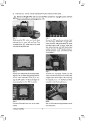
... completely lift the CPU socket lever and the metal load plate will be lifted as shown. Step 5: Push the CPU socket lever back into the motherboard CPU socket. B. Follow the steps below to the "REMOVE" mark) and then remove the cover. (DO NOT touch socket contacts. NOTE: Hold the CPU socket...
... completely lift the CPU socket lever and the metal load plate will be lifted as shown. Step 5: Push the CPU socket lever back into the motherboard CPU socket. B. Follow the steps below to the "REMOVE" mark) and then remove the cover. (DO NOT touch socket contacts. NOTE: Hold the CPU socket...
Manual
Page 15
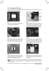
... the installation, check the back of the CPU cooler to the CPU fan header (CPU_FAN) on the motherboard. Push down each push pin. Step 6: Finally, attach the power connector of the motherboard. Hardware Installation Inadequately removing the CPU cooler may adhere to the CPU. Step 4: You should hear ...cooler atop the CPU, aligning the four push pins through the pin holes on the motherboard. 1-3-2 Installing the CPU Cooler Follow the steps below to correctly install the CPU cooler on the motherboard. (The following procedure uses Intel® boxed cooler as the picture above shows,...
... the installation, check the back of the CPU cooler to the CPU fan header (CPU_FAN) on the motherboard. Push down each push pin. Step 6: Finally, attach the power connector of the motherboard. Hardware Installation Inadequately removing the CPU cooler may adhere to the CPU. Step 4: You should hear ...cooler atop the CPU, aligning the four push pins through the pin holes on the motherboard. 1-3-2 Installing the CPU Cooler Follow the steps below to correctly install the CPU cooler on the motherboard. (The following procedure uses Intel® boxed cooler as the picture above shows,...
Manual
Page 16
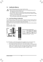
... the memory: •• Make sure that memory of the same capacity, brand, speed, and chips be used . (Go to GIGABYTE's website for the latest supported memory speeds and memory modules.) •• Always turn off the computer and unplug the power cord from...Double-Sided, "- -"=No Memory) DDR3_4 DDR3_2 DDR3_3 DDR3_1 Due to insert the memory, switch the direction. 1-4-1 Dual Channel Memory Configuration This motherboard provides four DDR3 memory sockets and supports Dual Channel Technology. The four DDR3 memory sockets are unable to CPU limitations, read the following guidelines...
... the memory: •• Make sure that memory of the same capacity, brand, speed, and chips be used . (Go to GIGABYTE's website for the latest supported memory speeds and memory modules.) •• Always turn off the computer and unplug the power cord from...Double-Sided, "- -"=No Memory) DDR3_4 DDR3_2 DDR3_3 DDR3_1 Due to insert the memory, switch the direction. 1-4-1 Dual Channel Memory Configuration This motherboard provides four DDR3 memory sockets and supports Dual Channel Technology. The four DDR3 memory sockets are unable to CPU limitations, read the following guidelines...
Manual
Page 17
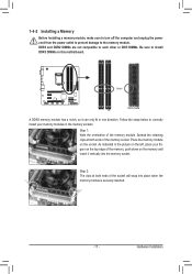
..., make sure to turn off the computer and unplug the power cord from the power outlet to prevent damage to install DDR3 DIMMs on this motherboard. As indicated in the picture on the socket.
..., make sure to turn off the computer and unplug the power cord from the power outlet to prevent damage to install DDR3 DIMMs on this motherboard. As indicated in the picture on the socket.
Manual
Page 18
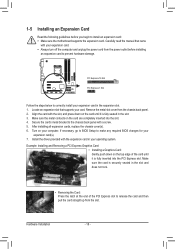
..., replace the chassis cover(s). 666 Turn on the top edge of the PCI Express slot to install an expansion card: •• Make sure the motherboard supports the expansion card. Carefully read the manual that supports your computer. Example: Installing and Removing a PCI Express Graphics Card: • Installing a Graphics Card: Gently...
..., replace the chassis cover(s). 666 Turn on the top edge of the PCI Express slot to install an expansion card: •• Make sure the motherboard supports the expansion card. Carefully read the manual that supports your computer. Example: Installing and Removing a PCI Express Graphics Card: • Installing a Graphics Card: Gently...
Manual
Page 20
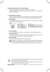
... have to an external audio system that your device and then remove it from the connector. Use this audio jack for the Onboard Graphics: This motherboard provides three video output ports: D-Sub, DVI-D, and HDMI. Connection/ Speed LED Activity LED LAN Port Connection/Speed LED: State Orange Green Off ...system provides an optical digital audio in devices such as an optical drive, walkman, etc. Do not rock it straight out from the motherboard. •• When removing the cable, pull it side to side to this feature, ensure that supports digital optical audio.
... have to an external audio system that your device and then remove it from the connector. Use this audio jack for the Onboard Graphics: This motherboard provides three video output ports: D-Sub, DVI-D, and HDMI. Connection/ Speed LED Activity LED LAN Port Connection/Speed LED: State Orange Green Off ...system provides an optical digital audio in devices such as an optical drive, walkman, etc. Do not rock it straight out from the motherboard. •• When removing the cable, pull it side to side to this feature, ensure that supports digital optical audio.
Manual
Page 21
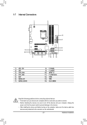
... 3) CPU_FAN 4) SYS_FAN 5) BAT 6) SATA3_0/1 7) SATA2_2/3/4/5 8) F_PANEL 9) F_AUDIO 10) SPDIF_O 11) F_USB1/2/3/4 12) COM 13) TPM 14) CLR_CMOS Read the following guidelines before turning on the motherboard. - 21 - Unplug the power cord from the power outlet to prevent damage to the devices. •• After installing the device and before connecting external...
... 3) CPU_FAN 4) SYS_FAN 5) BAT 6) SATA3_0/1 7) SATA2_2/3/4/5 8) F_PANEL 9) F_AUDIO 10) SPDIF_O 11) F_USB1/2/3/4 12) COM 13) TPM 14) CLR_CMOS Read the following guidelines before turning on the motherboard. - 21 - Unplug the power cord from the power outlet to prevent damage to the devices. •• After installing the device and before connecting external...
Manual
Page 22
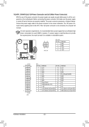
... can supply enough stable power to all devices are properly installed. If the 12V power connector is turned off and all the components on the motherboard. Connect the power supply cable to the CPU. 1/2) ATX_12V/ATX (2x2 12V Power Connector and 2x12 Main Power Connector) With the use of the power...
... can supply enough stable power to all devices are properly installed. If the 12V power connector is turned off and all the components on the motherboard. Connect the power supply cable to the CPU. 1/2) ATX_12V/ATX (2x2 12V Power Connector and 2x12 Main Power Connector) With the use of the power...
Manual
Page 23
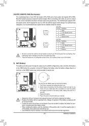
3/4) CPU_FAN/SYS_FAN (Fan Headers) The motherboard has a 4-pin CPU fan header (CPU_FAN) and a 4-pin system fan header (SYS_FAN). Definition 1 GND 2 +12V /Speed Control 3 Sense 4 Speed Control 1 SYS_FAN SYS_FAN: Pin No. Overheating ... face up). •• Used batteries must be handled in the CMOS when the computer is recommended that a system fan be lost. Hardware Installation The motherboard supports CPU fan speed control, which requires the use of the battery holder, making them short for one . You may be installed inside the chassis...
3/4) CPU_FAN/SYS_FAN (Fan Headers) The motherboard has a 4-pin CPU fan header (CPU_FAN) and a 4-pin system fan header (SYS_FAN). Definition 1 GND 2 +12V /Speed Control 3 Sense 4 Speed Control 1 SYS_FAN SYS_FAN: Pin No. Overheating ... face up). •• Used batteries must be handled in the CMOS when the computer is recommended that a system fan be lost. Hardware Installation The motherboard supports CPU fan speed control, which requires the use of the battery holder, making them short for one . You may be installed inside the chassis...


