User Manual
Page 3
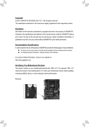
... The revision number on your motherboard revision before updating motherboard BIOS, drivers, or when looking for technical information. For example, "REV: 1.0" means the revision of the motherboard is the property of GIGABYTE. Changes to assist in any means without prior notice. ...; For detailed product information, carefully read the User's Manual. Check your motherboard looks like this manual may be made by GIGABYTE without GIGABYTE's prior written permission. Copyright © 2011 GIGA-BYTE TECHNOLOGY CO., LTD. The trademarks mentioned in this manual are legally ...
... The revision number on your motherboard revision before updating motherboard BIOS, drivers, or when looking for technical information. For example, "REV: 1.0" means the revision of the motherboard is the property of GIGABYTE. Changes to assist in any means without prior notice. ...; For detailed product information, carefully read the User's Manual. Check your motherboard looks like this manual may be made by GIGABYTE without GIGABYTE's prior written permission. Copyright © 2011 GIGA-BYTE TECHNOLOGY CO., LTD. The trademarks mentioned in this manual are legally ...
User Manual
Page 4
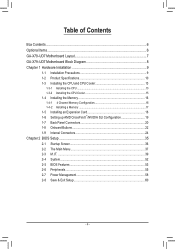
Table of Contents Box Contents...6 Optional Items...6 GA-X79-UD7 Motherboard Layout 7 GA-X79-UD7 Motherboard Block Diagram 8 Chapter 1 Hardware Installation 9 1-1 Installation Precautions 9 1-2 Product Specifications 10 1-3 Installing the CPU and CPU Cooler 13 ...AMD CrossFireX™/NVIDIA SLI Configuration 19 1-7 Back Panel Connectors 20 1-8 Onboard Buttons 22 1-9 Internal Connectors 24 Chapter 2 BIOS Setup 35 2-1 Startup Screen 36 2-2 The Main Menu 37 2-3 M.I.T...39 2-4 System...52 2-5 BIOS Features 53 2-6 Peripherals...55 2-7 Power Management 58 2-8 Save & Exit Setup 60 - 4 -
Table of Contents Box Contents...6 Optional Items...6 GA-X79-UD7 Motherboard Layout 7 GA-X79-UD7 Motherboard Block Diagram 8 Chapter 1 Hardware Installation 9 1-1 Installation Precautions 9 1-2 Product Specifications 10 1-3 Installing the CPU and CPU Cooler 13 ...AMD CrossFireX™/NVIDIA SLI Configuration 19 1-7 Back Panel Connectors 20 1-8 Onboard Buttons 22 1-9 Internal Connectors 24 Chapter 2 BIOS Setup 35 2-1 Startup Screen 36 2-2 The Main Menu 37 2-3 M.I.T...39 2-4 System...52 2-5 BIOS Features 53 2-6 Peripherals...55 2-7 Power Management 58 2-8 Save & Exit Setup 60 - 4 -
User Manual
Page 5
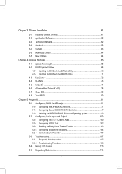
...64 3-7 New Utilities...64 Chapter 4 Unique Features 65 4-1 Xpress Recovery2 65 4-2 BIOS Update Utilities 68 4-2-1 Updating the BIOS with the Q-Flash Utility 68 4-2-2 Updating the BIOS with the @BIOS Utility 71 4-3 EasyTune 6...72 4-4 Q-Share...73 4-5 Smart 6™ ...74 ...4-6 eXtreme Hard Drive (X.H.D 78 4-7 Cloud OC...79 4-8 TouchBIOS...80 Chapter 5 Appendix...81 5-1 Configuring SATA Hard Drive(s 81 5-1-1 Configuring Intel X79...
...64 3-7 New Utilities...64 Chapter 4 Unique Features 65 4-1 Xpress Recovery2 65 4-2 BIOS Update Utilities 68 4-2-1 Updating the BIOS with the Q-Flash Utility 68 4-2-2 Updating the BIOS with the @BIOS Utility 71 4-3 EasyTune 6...72 4-4 Q-Share...73 4-5 Smart 6™ ...74 ...4-6 eXtreme Hard Drive (X.H.D 78 4-7 Cloud OC...79 4-8 TouchBIOS...80 Chapter 5 Appendix...81 5-1 Configuring SATA Hard Drive(s 81 5-1-1 Configuring Intel X79...
User Manual
Page 8
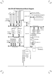
GA-X79-UD7 Motherboard Block Diagram 1 PCI Express x16 2 PCI Express x8 1 PCI 1 PCI Express x16 Express x8 or LGA2011 CPU CPU CLK+/- (100 MHz) DDR3 2133/1866/... (100 MHz) RJ45 Intel GbE LAN phy DMI 2.0 PCI Express Bus x1 Marvell 88SE9172 x1 Marvell 88SE9172 PCIe CLK (100 MHz) Intel® X79 2 SATA 6Gb/s 2 SATA 6Gb/s Dual BIOS 4 SATA 3Gb/s 2 SATA 6Gb/s 14 USB 2.0/1.1 x1 x1 x1 x1 PCI Express Bus LPC Bus IT8728 CODEC PS/2 KB/Mouse Surround Speaker...
GA-X79-UD7 Motherboard Block Diagram 1 PCI Express x16 2 PCI Express x8 1 PCI 1 PCI Express x16 Express x8 or LGA2011 CPU CPU CLK+/- (100 MHz) DDR3 2133/1866/... (100 MHz) RJ45 Intel GbE LAN phy DMI 2.0 PCI Express Bus x1 Marvell 88SE9172 x1 Marvell 88SE9172 PCIe CLK (100 MHz) Intel® X79 2 SATA 6Gb/s 2 SATA 6Gb/s Dual BIOS 4 SATA 3Gb/s 2 SATA 6Gb/s 14 USB 2.0/1.1 x1 x1 x1 x1 PCI Express Bus LPC Bus IT8728 CODEC PS/2 KB/Mouse Surround Speaker...
User Manual
Page 11
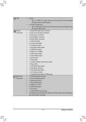
...;Š 1 x CPU Ratio Up button ŠŠ 1 x Trusted Platform Module (TPM) header ŠŠ 1 x PS/2 keyboard/mouse port ŠŠ 1 x CPU overclocking button ŠŠ 1 x BIOS switch button ŠŠ 1 x Clear CMOS button ŠŠ 8 x USB 2.0/1.1 ports ŠŠ 2 x USB 3.0/2.0 ports ŠŠ 1 x RJ-45 port ŠŠ 1 x optical S/PDIF Out...
...;Š 1 x CPU Ratio Up button ŠŠ 1 x Trusted Platform Module (TPM) header ŠŠ 1 x PS/2 keyboard/mouse port ŠŠ 1 x CPU overclocking button ŠŠ 1 x BIOS switch button ŠŠ 1 x Clear CMOS button ŠŠ 8 x USB 2.0/1.1 ports ŠŠ 2 x USB 3.0/2.0 ports ŠŠ 1 x RJ-45 port ŠŠ 1 x optical S/PDIF Out...
User Manual
Page 12
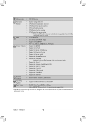
...ŠŠ Use of licensed AMI EFI BIOS ŠŠ Support for DualBIOS™ ŠŠ PnP 1.0a, DMI 2.0, SM BIOS 2.6, ACPI 2.0a Unique Features ŠŠ Support for @BIOS ŠŠ Support for Q-Flash ŠŠ Support for Xpress BIOS Rescue ŠŠ Support for Download Center...Windows 7/Vista/XP Form Factor ŠŠ XL-ATX Form Factor; 32.4cm x 25.3cm (Go to GIGABYTE's website for the latest chassis support list.) * GIGABYTE reserves the right to make any changes to the product specifications and product-related information without prior notice. I/O ...
...ŠŠ Use of licensed AMI EFI BIOS ŠŠ Support for DualBIOS™ ŠŠ PnP 1.0a, DMI 2.0, SM BIOS 2.6, ACPI 2.0a Unique Features ŠŠ Support for @BIOS ŠŠ Support for Q-Flash ŠŠ Support for Xpress BIOS Rescue ŠŠ Support for Download Center...Windows 7/Vista/XP Form Factor ŠŠ XL-ATX Form Factor; 32.4cm x 25.3cm (Go to GIGABYTE's website for the latest chassis support list.) * GIGABYTE reserves the right to make any changes to the product specifications and product-related information without prior notice. I/O ...
User Manual
Page 16
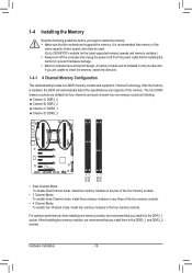
...motherboard provides four DDR3 memory sockets and supports 4 Channel Technology. Hardware Installation - 16 - A memory module can be used. (Go to GIGABYTE's website for the latest supported memory speeds and memory modules.) •• Always turn off the computer and unplug the power cord from...guidelines before installing the memory to prevent hardware damage. •• Memory modules have a foolproof design. It is installed, the BIOS will automatically detect the specifications and capacity of the four memory sockets. •• 4 Channel Mode: To enable four Channel ...
...motherboard provides four DDR3 memory sockets and supports 4 Channel Technology. Hardware Installation - 16 - A memory module can be used. (Go to GIGABYTE's website for the latest supported memory speeds and memory modules.) •• Always turn off the computer and unplug the power cord from...guidelines before installing the memory to prevent hardware damage. •• Memory modules have a foolproof design. It is installed, the BIOS will automatically detect the specifications and capacity of the four memory sockets. •• 4 Channel Mode: To enable four Channel ...
User Manual
Page 18
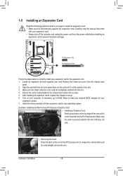
... the metal contacts on your operating system. Turn on the card are completely inserted into the PCI Express slot. If necessary, go to BIOS Setup to make any required BIOS changes for your expansion card in the slot and does not rock. •• Removing the Card: Press the latch at the...
... the metal contacts on your operating system. Turn on the card are completely inserted into the PCI Express slot. If necessary, go to BIOS Setup to make any required BIOS changes for your expansion card in the slot and does not rock. •• Removing the Card: Press the latch at the...
User Manual
Page 20
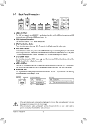
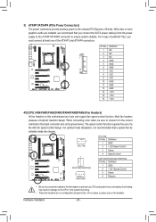
... needed. The green LED indicates the main BIOS is active and the blue LED indicates the backup BIOS is compatible to the USB 2.0/1.1 specification. date information and BIOS configurations) and reset the CMOS values to switch between the main BIOS and backup BIOS. USB 3.0/2.0 Port The USB 3.0 port ... short inside the cable connector. To return to the defaults, press this button to reduce BIOS failure during overclocking. BIOS Switch Button The button allows users to easily select a different BIOS for USB devices such as a USB keyboard/mouse, USB printer, USB flash drive and etc...
... needed. The green LED indicates the main BIOS is active and the blue LED indicates the backup BIOS is compatible to the USB 2.0/1.1 specification. date information and BIOS configurations) and reset the CMOS values to switch between the main BIOS and backup BIOS. USB 3.0/2.0 Port The USB 3.0 port ... short inside the cable connector. To return to the defaults, press this button to reduce BIOS failure during overclocking. BIOS Switch Button The button allows users to easily select a different BIOS for USB devices such as a USB keyboard/mouse, USB printer, USB flash drive and etc...
User Manual
Page 22
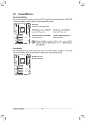
... CPU Ratio Down Button (RATIO_DW) Lowers the CPU ratio. Before using the overclocking buttons, make sure to load the optimized defaults in BIOS, DOS or Windows), including CPU Ratio, BCLK and even change hardware components or conduct hardware testing. Quick Buttons The power button and reset... button allow users to overclock the CPU in real-time and at anytime (whether in BIOS Setup to return the BIOS settings to 0.1 MHz. PW_SW: Power button RST_SW: Reset button Hardware Installation - 22 - CPU BCLK Down Button (FREQ_DW) Lowers...
... CPU Ratio Down Button (RATIO_DW) Lowers the CPU ratio. Before using the overclocking buttons, make sure to load the optimized defaults in BIOS, DOS or Windows), including CPU Ratio, BCLK and even change hardware components or conduct hardware testing. Quick Buttons The power button and reset... button allow users to overclock the CPU in real-time and at anytime (whether in BIOS Setup to return the BIOS settings to 0.1 MHz. PW_SW: Power button RST_SW: Reset button Hardware Installation - 22 - CPU BCLK Down Button (FREQ_DW) Lowers...
User Manual
Page 23
... 1 23 1 DIP 1 23 1 DIP 1 23 1 1 DIP 1 VCORE DIP 1 23 1 Pin 1 QPIVTT DIP 1 23 1 Pin 1 DDR_15V_DAIP 1 23 1 Pin 1 DDR_15V_B BIOS SwitcheBrIO(XS58SAw-iOtcChBe) rIO(XS5S8Aw-itOchCeB)rIO(XS58SAw-iOtcCheB) rIO(XS5S8Aw-iOtcChBe)rIO(XS5S8Aw-itOchCeB)rIO(XS5S8Aw-iOtcChe)r (X58A-OC) DB_PORT DB_PORT DB_PORT DB_PORT DB_PORT...eXpco5tow8rAe(-rSOcAPCoTCn)AIne)e(Xpcot5ow8rAe(Sr-OcAoCTnA)n)e(Xc5to8rA(-SOACT)A)(X58A-OC) 1 23 1 23 DIP DIP 1 2 3 SMB_CPT SMB_CPT SM (GA-IVB) (GA-IVB) (G Pin No. You can use a multimeter to the pin 1 (+12V). F_USB30 F_USB30 F_USB30 F_USB30 F_USB30F_AFU_DUISOB(3H0)F_AFU_UDSIOB...
... 1 23 1 DIP 1 23 1 DIP 1 23 1 1 DIP 1 VCORE DIP 1 23 1 Pin 1 QPIVTT DIP 1 23 1 Pin 1 DDR_15V_DAIP 1 23 1 Pin 1 DDR_15V_B BIOS SwitcheBrIO(XS58SAw-iOtcChBe) rIO(XS5S8Aw-itOchCeB)rIO(XS58SAw-iOtcCheB) rIO(XS5S8Aw-iOtcChBe)rIO(XS5S8Aw-itOchCeB)rIO(XS5S8Aw-iOtcChe)r (X58A-OC) DB_PORT DB_PORT DB_PORT DB_PORT DB_PORT...eXpco5tow8rAe(-rSOcAPCoTCn)AIne)e(Xpcot5ow8rAe(Sr-OcAoCTnA)n)e(Xc5to8rA(-SOACT)A)(X58A-OC) 1 23 1 23 DIP DIP 1 2 3 SMB_CPT SMB_CPT SM (GA-IVB) (GA-IVB) (G Pin No. You can use a multimeter to the pin 1 (+12V). F_USB30 F_USB30 F_USB30 F_USB30 F_USB30F_AFU_DUISOB(3H0)F_AFU_UDSIOB...
User Manual
Page 26
... a fan with fan speed control design. For 4-way CrossFireX™/SLI, you connect the SATA power cable(s) from overheating. F_PANEL(NH) PWM Switch (X58A-OC) BIOS Switcher (X58A-OC) 1 M_SATA 3) ATX4P1/ATX4P4 (PCIe Power Connectors) The power connectors provide auxiliary power to prevent your CPU and system from the power supply...
... a fan with fan speed control design. For 4-way CrossFireX™/SLI, you connect the SATA power cable(s) from overheating. F_PANEL(NH) PWM Switch (X58A-OC) BIOS Switcher (X58A-OC) 1 M_SATA 3) ATX4P1/ATX4P4 (PCIe Power Connectors) The power connectors provide auxiliary power to prevent your CPU and system from the power supply...
User Manual
Page 29
...CMOS Jumper) Use this jumper to touch the positive and negative terminals of purchase or local dealer if you are not able to Chapter 2, "BIOS Setup," for 5 seconds.) 3. Hardware Installation Replace the battery. 4. Plug in accordance with an incorrect model. •• Contact the ...place of the battery holder, making them short for BIOS configurations). - 29 - Danger of explosion if the battery is turned off your computer and unplug the power cord. 2. Open: Normal Short: Clear...
...CMOS Jumper) Use this jumper to touch the positive and negative terminals of purchase or local dealer if you are not able to Chapter 2, "BIOS Setup," for 5 seconds.) 3. Hardware Installation Replace the battery. 4. Plug in accordance with an incorrect model. •• Contact the ...place of the battery holder, making them short for BIOS configurations). - 29 - Danger of explosion if the battery is turned off your computer and unplug the power cord. 2. Open: Normal Short: Clear...
User Manual
Page 30
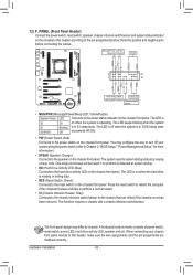
...;• RES (Reset Switch, Green): Connects to the speaker on the chassis front panel. When connecting your system using the power switch (refer to Chapter 2, "BIOS Setup," "Power Management Setup," for more information). •• SPEAK (Speaker, Orange): Connects to the reset switch on the chassis that can detect if the...
...;• RES (Reset Switch, Green): Connects to the speaker on the chassis front panel. When connecting your system using the power switch (refer to Chapter 2, "BIOS Setup," "Power Management Setup," for more information). •• SPEAK (Speaker, Orange): Connects to the reset switch on the chassis that can detect if the...
User Manual
Page 31
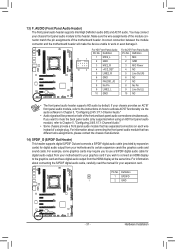
...FAUDIO_JD 7 NC 8 No Pin 8 No Pin 9 LINE2_L 9 Line Out (L) 10 GND 10 NC F_PANEL (H61M-D2) DIP 1 23 1 DB_PORT BIOS Switcher (X58A-OC) DIP 1 23 1 •• The front panel audio header sup1ports HD audio by expansion cardsP)CfIoerpodwigeritcaolnaneucdtoiro(SoAuTtAp)(uXt5f8rAo-mOC)your chassis... different wire assignments, please contact the chassis manufacturer. Definition 1 SPDIFO 1 2 GND ACPI_CPT (GA-IVB) SMB_CPT (GA-IVB) CLR_CMOS CI DIS_ME GP15_CPT (GA-IVB) XDP_CPU XDP_PCH (GA-IVB) - 31 - Pin No. Make sure the wire assignments of the module connector match...
...FAUDIO_JD 7 NC 8 No Pin 8 No Pin 9 LINE2_L 9 Line Out (L) 10 GND 10 NC F_PANEL (H61M-D2) DIP 1 23 1 DB_PORT BIOS Switcher (X58A-OC) DIP 1 23 1 •• The front panel audio header sup1ports HD audio by expansion cardsP)CfIoerpodwigeritcaolnaneucdtoiro(SoAuTtAp)(uXt5f8rAo-mOC)your chassis... different wire assignments, please contact the chassis manufacturer. Definition 1 SPDIFO 1 2 GND ACPI_CPT (GA-IVB) SMB_CPT (GA-IVB) CLR_CMOS CI DIS_ME GP15_CPT (GA-IVB) XDP_CPU XDP_PCH (GA-IVB) - 31 - Pin No. Make sure the wire assignments of the module connector match...
User Manual
Page 33
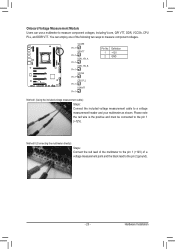
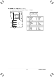
Hardware Installation 17) TPM (Trusted Platform Module Header) You may connect a TPM (Trusted Platform Module) to this header. 19 TPM w/housing 20 Pin No. 1 2 3 4 5 6 7 8 9 10 Definition LCLK GND LFRAME No Pin LRESET NC LAD3 LAD2 VCC3 LAD1 BIO DB_PORT 1 Voltage measurement module(X58A-OC) P 2 Pin No. 11 12 13 14 15 16 17 18 19 20 Definition LAD0 GND PCIe power connector (SATA)(X58A-OC) NC ID SB3V SERIRQ GND NC NC SUSCLK - 33 -
Hardware Installation 17) TPM (Trusted Platform Module Header) You may connect a TPM (Trusted Platform Module) to this header. 19 TPM w/housing 20 Pin No. 1 2 3 4 5 6 7 8 9 10 Definition LCLK GND LFRAME No Pin LRESET NC LAD3 LAD2 VCC3 LAD1 BIO DB_PORT 1 Voltage measurement module(X58A-OC) P 2 Pin No. 11 12 13 14 15 16 17 18 19 20 Definition LAD0 GND PCIe power connector (SATA)(X58A-OC) NC ID SB3V SERIRQ GND NC NC SUSCLK - 33 -
User Manual
Page 35
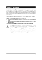
...35 - For instructions on . To upgrade the BIOS, use either the GIGABYTE Q-Flash or @BIOS utility. •• Q-Flash allows the user to Chapter 4, "BIOS Update Utilities." •• Because BIOS flashing is potentially risky, if you not flash the BIOS. BIOS Setup If this occurs, try to clear the ... of the battery or the clear CMOS jumper/button in Chapter 1 for how to activate certain system features. Chapter 2 BIOS Setup BIOS (Basic Input and Output System) records hardware parameters of the system in the CMOS on the motherboard supplies the necessary power...
...35 - For instructions on . To upgrade the BIOS, use either the GIGABYTE Q-Flash or @BIOS utility. •• Q-Flash allows the user to Chapter 4, "BIOS Update Utilities." •• Because BIOS flashing is potentially risky, if you not flash the BIOS. BIOS Setup If this occurs, try to clear the ... of the battery or the clear CMOS jumper/button in Chapter 1 for how to activate certain system features. Chapter 2 BIOS Setup BIOS (Basic Input and Output System) records hardware parameters of the system in the CMOS on the motherboard supplies the necessary power...
User Manual
Page 36
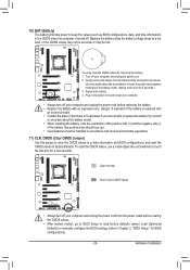
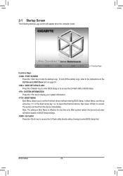
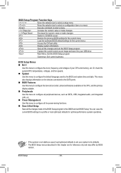
... press to skip the startup Logo. After system restart, the device boot order will still be based on page 53. : BIOS SETUP\Q-FLASH Press the key to enter BIOS Setup or to access the Q-Flash utility in Boot Menu is effective for one time only. The system will appear when the... turn off the startup Logo, refer to the instructions on the Full Screen LOGO Show item on BIOS Setup settings. : Q-FLASH Press the key to enter BIOS Setup first. BIOS Setup - 36 - Note: The setting in BIOS Setup. : SYSTEM INFORMATION Press the key to display your system information. : BOOT MENU Boot Menu allows...
... press to skip the startup Logo. After system restart, the device boot order will still be based on page 53. : BIOS SETUP\Q-FLASH Press the key to enter BIOS Setup or to access the Q-Flash utility in Boot Menu is effective for one time only. The system will appear when the... turn off the startup Logo, refer to the instructions on the Full Screen LOGO Show item on BIOS Setup settings. : Q-FLASH Press the key to enter BIOS Setup first. BIOS Setup - 36 - Note: The setting in BIOS Setup. : SYSTEM INFORMATION Press the key to display your system information. : BOOT MENU Boot Menu allows...
User Manual
Page 37
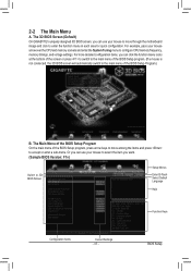
...icons at the bottom of the screen or press to switch to the main menu of the BIOS Setup Program.) B. 2-2 The Main Menu A. The 3D BIOS Screen (Default) On GIGABYTE's uniquely designed 3D BIOS screen, you can use your mouse arrow over the CPU and memory sockets and enter the System... Tuning menu to the main menu of the BIOS Setup program. (If a mouse is not connected, the 3D BIOS screen will automatically switch to...
...icons at the bottom of the screen or press to switch to the main menu of the BIOS Setup Program.) B. 2-2 The Main Menu A. The 3D BIOS Screen (Default) On GIGABYTE's uniquely designed 3D BIOS screen, you can use your mouse arrow over the CPU and memory sockets and enter the System... Tuning menu to the main menu of the BIOS Setup program. (If a mouse is not connected, the 3D BIOS screen will automatically switch to...
User Manual
Page 38
... voltages of your CPU and memory, etc. This menu also displays information on the devices connected to the SATA ports. „„ BIOS Features Use this menu to configure the device boot order, advanced features available on a menu Execute command or enter a menu / Increase ...the numeric value or make changes / Decrease the numeric value or make changes Switch to 3D BIOS screen Restore the previous BIOS settings for the current menu Load the optimized BIOS default settings for the current menu Access the Q-Flash utility Display system information Save all the changes...
... voltages of your CPU and memory, etc. This menu also displays information on the devices connected to the SATA ports. „„ BIOS Features Use this menu to configure the device boot order, advanced features available on a menu Execute command or enter a menu / Increase ...the numeric value or make changes / Decrease the numeric value or make changes Switch to 3D BIOS screen Restore the previous BIOS settings for the current menu Load the optimized BIOS default settings for the current menu Access the Q-Flash utility Display system information Save all the changes...


