User Manual
Page 11
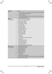
... 4 USB 3.0/2.0 ports (2 ports on the back panel, 2 ports available through the internal USB header) ŠŠ 1 x 24-pin ATX main power connector ŠŠ 2 x 8-pin ATX 12V power connectors ŠŠ 2 x PCIe power connectors ŠŠ 6 x SATA 6Gb/s connectors ŠŠ 4 x SATA 3Gb/s connectors ŠŠ 1 x CPU fan header ŠŠ 6 x system fan headers ŠŠ 1 x front panel header Š...
... 4 USB 3.0/2.0 ports (2 ports on the back panel, 2 ports available through the internal USB header) ŠŠ 1 x 24-pin ATX main power connector ŠŠ 2 x 8-pin ATX 12V power connectors ŠŠ 2 x PCIe power connectors ŠŠ 6 x SATA 6Gb/s connectors ŠŠ 4 x SATA 3Gb/s connectors ŠŠ 1 x CPU fan header ŠŠ 6 x system fan headers ŠŠ 1 x front panel header Š...

User Manual
Page 25
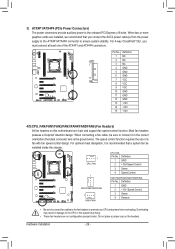
... 12V Power Connectors and 2x12 Main Power Connector) With the use of the power connector, the power supply can lead to the power connector in the correct orientation. Before connecting the power connector, first make sure the power supply is not connected, the computer will not start. Connect the power supply cable to an unstable or unbootable system. 1 5 4 8 ATX_12V_2X/ATX_12V_2X1 ATX_12V_2X/ATX_12V_2X1: Pin No...
... 12V Power Connectors and 2x12 Main Power Connector) With the use of the power connector, the power supply can lead to the power connector in the correct orientation. Before connecting the power connector, first make sure the power supply is not connected, the computer will not start. Connect the power supply cable to an unstable or unbootable system. 1 5 4 8 ATX_12V_2X/ATX_12V_2X1 ATX_12V_2X/ATX_12V_2X1: Pin No...
User Manual
Page 26
... headers possess a foolproof insertion design. The speed control function requires the use of the ATX4P1 and ATX4P4 connectors. 1 DIP 1 23 PCIe power connector (SATA)(X58A-OC) DIP 1 23 1 DIP 1 23 1 Voltage measurement module(X58A-OC) DB_PORT Pin No. For optimum heat dissipation, it in damage to the onboard PCI Express x16 slots. Do not...
... headers possess a foolproof insertion design. The speed control function requires the use of the ATX4P1 and ATX4P4 connectors. 1 DIP 1 23 PCIe power connector (SATA)(X58A-OC) DIP 1 23 1 DIP 1 23 1 Voltage measurement module(X58A-OC) DB_PORT Pin No. For optimum heat dissipation, it in damage to the onboard PCI Express x16 slots. Do not...
User Manual
Page 31
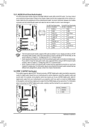
...audio output from the HDMI display at the same time. Pin No. Definition 1 SPDIFO 1 2 GND ACPI_CPT (GA-IVB) SMB_CPT (GA-IVB) CLR_CMOS CI DIS_ME GP15_CPT (GA-IVB) XDP_CPU XDP_PCH (GA-IVB) - 31 - Definition 9 1 1 MIC2_L 2 F_PAGNENLD(NH) 3 MIC2_R 1 MIC 2 GND 3 MIC Power 10 2 4 -ACZ_DET 5 LINE2_R 4 NC 5 Line...expansion cardsP)CfIoerpodwigeritcaolnaneucdtoiro(SoAuTtAp)(uXt5f8rAo-mOC)your expansion card. Make sure the wire assignments of the module connector match the pin assignments of a single plug. Hardware Installation You may require you to use a S/PDIF digital audio...
...audio output from the HDMI display at the same time. Pin No. Definition 1 SPDIFO 1 2 GND ACPI_CPT (GA-IVB) SMB_CPT (GA-IVB) CLR_CMOS CI DIS_ME GP15_CPT (GA-IVB) XDP_CPU XDP_PCH (GA-IVB) - 31 - Definition 9 1 1 MIC2_L 2 F_PAGNENLD(NH) 3 MIC2_R 1 MIC 2 GND 3 MIC Power 10 2 4 -ACZ_DET 5 LINE2_R 4 NC 5 Line...expansion cardsP)CfIoerpodwigeritcaolnaneucdtoiro(SoAuTtAp)(uXt5f8rAo-mOC)your expansion card. Make sure the wire assignments of the module connector match the pin assignments of a single plug. Hardware Installation You may require you to use a S/PDIF digital audio...
User Manual
Page 32
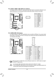
... 1+ 4 GND 5 SSTX16 SSTX1+ 7 GND 8 D19 D1+ 10 NC Pin No. 11 12 13 14 15 16 17 18 19 20 Definition D2+ D2GND SSTX2+ SSTX2GND SSRX2+ SSRX2VBUS No Pin Voltage measurement module(X58A-OC) PCIe power connector (SATA)(X58A-O When the system is in S4/S5 mode, only the USB... ports routed to this header. 1 11 DB_PORT 10 20 Pin No. Definition 1 Power (5V) 2 Power (5V) 9 1 10 2 3 USB DX- 4 USB DY...
... 1+ 4 GND 5 SSTX16 SSTX1+ 7 GND 8 D19 D1+ 10 NC Pin No. 11 12 13 14 15 16 17 18 19 20 Definition D2+ D2GND SSTX2+ SSTX2GND SSRX2+ SSRX2VBUS No Pin Voltage measurement module(X58A-OC) PCIe power connector (SATA)(X58A-O When the system is in S4/S5 mode, only the USB... ports routed to this header. 1 11 DB_PORT 10 20 Pin No. Definition 1 Power (5V) 2 Power (5V) 9 1 10 2 3 USB DX- 4 USB DY...
User Manual
Page 33
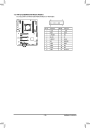
Hardware Installation 17) TPM (Trusted Platform Module Header) You may connect a TPM (Trusted Platform Module) to this header. 19 TPM w/housing 20 Pin No. 1 2 3 4 5 6 7 8 9 10 Definition LCLK GND LFRAME No Pin LRESET NC LAD3 LAD2 VCC3 LAD1 BIO DB_PORT 1 Voltage measurement module(X58A-OC) P 2 Pin No. 11 12 13 14 15 16 17 18 19 20 Definition LAD0 GND PCIe power connector (SATA)(X58A-OC) NC ID SB3V SERIRQ GND NC NC SUSCLK - 33 -
Hardware Installation 17) TPM (Trusted Platform Module Header) You may connect a TPM (Trusted Platform Module) to this header. 19 TPM w/housing 20 Pin No. 1 2 3 4 5 6 7 8 9 10 Definition LCLK GND LFRAME No Pin LRESET NC LAD3 LAD2 VCC3 LAD1 BIO DB_PORT 1 Voltage measurement module(X58A-OC) P 2 Pin No. 11 12 13 14 15 16 17 18 19 20 Definition LAD0 GND PCIe power connector (SATA)(X58A-OC) NC ID SB3V SERIRQ GND NC NC SUSCLK - 33 -


