
Manual
Page 1
GA-X58A-UD9 LGA1366 socket motherboard for Intel® Core™ i7 processor family User's Manual Rev. 1001 12ME-X58AUD9-1001R
GA-X58A-UD9 LGA1366 socket motherboard for Intel® Core™ i7 processor family User's Manual Rev. 1001 12ME-X58AUD9-1001R

Manual
Page 3
... number on our website. Check your motherboard looks like this manual may be reproduced, copied, translated, transmitted, or published in the use GIGABYTE's unique features, read the User's Manual. Changes to assist in any means without prior notice. Documentation... means the revision of the motherboard is the property of this manual are legally registered to use of GIGABYTE. Example: All rights reserved. Disclaimer Information in this manual may be made by GIGABYTE without GIGABYTE's prior written permission. For instructions on how to their respective owners...
... number on our website. Check your motherboard looks like this manual may be reproduced, copied, translated, transmitted, or published in the use GIGABYTE's unique features, read the User's Manual. Changes to assist in any means without prior notice. Documentation... means the revision of the motherboard is the property of this manual are legally registered to use of GIGABYTE. Example: All rights reserved. Disclaimer Information in this manual may be made by GIGABYTE without GIGABYTE's prior written permission. For instructions on how to their respective owners...

Manual
Page 5
Chapter 3 Drivers Installation 69 3-1 Installing Chipset Drivers 69 3-2 Application Software 70 3-3 Technical Manuals 70 3-4 Contact...71 3-5 System...71 3-6 Download Center 72 3-7 New Utilities...72 Chapter 4 Unique Features 73 4-1 Xpress Recovery2 ... 88 4-9 Teaming 89 Chapter 5 Appendix...91 5-1 Configuring SATA Hard Drive(s 91 5-1-1 Configuring Intel ICH10R SATA Controllers 91 5-1-2 Configuring JMicron JMB362/GIGABYTE SATA2 SATA Controller 99 5-1-3 Configuring Marvell 9128 SATA Controller 105 5-1-4 Making a SATA RAID/AHCI Driver Diskette 110 5-1-5 Installing the SATA RAID/AHCI ...
Chapter 3 Drivers Installation 69 3-1 Installing Chipset Drivers 69 3-2 Application Software 70 3-3 Technical Manuals 70 3-4 Contact...71 3-5 System...71 3-6 Download Center 72 3-7 New Utilities...72 Chapter 4 Unique Features 73 4-1 Xpress Recovery2 ... 88 4-9 Teaming 89 Chapter 5 Appendix...91 5-1 Configuring SATA Hard Drive(s 91 5-1-1 Configuring Intel ICH10R SATA Controllers 91 5-1-2 Configuring JMicron JMB362/GIGABYTE SATA2 SATA Controller 99 5-1-3 Configuring Marvell 9128 SATA Controller 105 5-1-4 Making a SATA RAID/AHCI Driver Diskette 110 5-1-5 Installing the SATA RAID/AHCI ...

Manual
Page 6
The box contents are for reference only. Box Contents GA-X58A-UD9 motherboard Motherboard driver disk User's Manual Quick Installation Guide One IDE cable Four SATA 3Gb/s cables One SATA bracket I/O Shield One Hybrid Silent-Pipe module kit One 2-Way SLI bridge connector ...
The box contents are for reference only. Box Contents GA-X58A-UD9 motherboard Motherboard driver disk User's Manual Quick Installation Guide One IDE cable Four SATA 3Gb/s cables One SATA bracket I/O Shield One Hybrid Silent-Pipe module kit One 2-Way SLI bridge connector ...
Manual
Page 9
Prior to installation, carefully read the user's manual and follow these procedures: • Prior to installation, do not remove or break motherboard S/N (Serial Number) sticker or warranty sticker provided by unplugging the power ...
Prior to installation, carefully read the user's manual and follow these procedures: • Prior to installation, do not remove or break motherboard S/N (Serial Number) sticker or warranty sticker provided by unplugging the power ...
Manual
Page 15
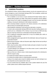
... push pin. (Turning the push pin along the direction of arrow is to remove the cooler, on the contrary, is to your CPU cooler installation manual for instructions on installing the cooler.) Step 5: After the installation, check the back of the motherboard. Use extreme care when removing the CPU cooler because...
... push pin. (Turning the push pin along the direction of arrow is to remove the cooler, on the contrary, is to your CPU cooler installation manual for instructions on installing the cooler.) Step 5: After the installation, check the back of the motherboard. Use extreme care when removing the CPU cooler because...

Manual
Page 19
... fully inserted into the slot. 4. 1-6 Installing an Expansion Card Read the following guidelines before installing an expansion card to prevent hardware damage. Carefully read the manual that supports your expansion card. • Always turn off the computer and unplug the power cord from the chassis back panel. 2. Remove the metal slot...
... fully inserted into the slot. 4. 1-6 Installing an Expansion Card Read the following guidelines before installing an expansion card to prevent hardware damage. Carefully read the manual that supports your expansion card. • Always turn off the computer and unplug the power cord from the chassis back panel. 2. Remove the metal slot...
Manual
Page 20
... with the bridge connector to the PCIE_12V_1 and PCIE_12V_2 connectors, or system instability may be inserted with sufficient power is recommended (Note 2) (refer to the manual of the bridge connector when installing. a - - - - - - - - 3-Way a a a - - - - - - - - 4-Way...
... with the bridge connector to the PCIE_12V_1 and PCIE_12V_2 connectors, or system instability may be inserted with sufficient power is recommended (Note 2) (refer to the manual of the bridge connector when installing. a - - - - - - - - 3-Way a a a - - - - - - - - 4-Way...

Manual
Page 21
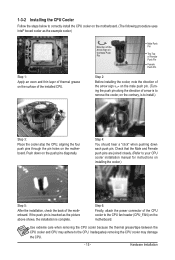
... the Set SLI and PhysX configuration screen and ensure PhysX and 3-way are enabled. Click OK to apply. Click OK to apply. C-2. Browse to the manual that came with your graphics cards for enabling CrossFireX/SLI technology may differ by graphics cards. Refer to the Set SLI and PhysX configuration screen...
... the Set SLI and PhysX configuration screen and ensure PhysX and 3-way are enabled. Click OK to apply. Click OK to apply. C-2. Browse to the manual that came with your graphics cards for enabling CrossFireX/SLI technology may differ by graphics cards. Refer to the Set SLI and PhysX configuration screen...

Manual
Page 36
For information about connecting the S/PDIF digital audio cable, carefully read the manual for digital audio output from the HDMI display at the same time. Definition 1 Power 2 SPDIFI 3 GND 17) SPDIF_O (S/PDIF Out Header) This header supports digital S/...
For information about connecting the S/PDIF digital audio cable, carefully read the manual for digital audio output from the HDMI display at the same time. Definition 1 Power 2 SPDIFI 3 GND 17) SPDIF_O (S/PDIF Out Header) This header supports digital S/...
Manual
Page 45
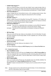
... (Note) Allows you to set the QPI clock ratio. When enabled, the CPU core frequency and voltage will be reduced during system halt state to manually set the CPU base clock. Note: If your system fails to boot after overclocking, please wait for automated system reboot, or clear the CMOS values...
... (Note) Allows you to set the QPI clock ratio. When enabled, the CPU core frequency and voltage will be reduced during system halt state to manually set the CPU base clock. Note: If your system fails to boot after overclocking, please wait for automated system reboot, or clear the CMOS values...

Manual
Page 46
.... CPU Clock Skew Allows you to the Chipset clock. Disabled Disables this feature. Options are : 0ps~750ps. (Default: 0ps) IOH Clock Skew Allows you to manually set the CPU clock prior to adjust the amplitude of the memory being used; Extreme Memory Profile (X.M.P.) (Note) Allows the BIOS to read the SPD...
.... CPU Clock Skew Allows you to the Chipset clock. Disabled Disables this feature. Options are : 0ps~750ps. (Default: 0ps) IOH Clock Skew Allows you to manually set the CPU clock prior to adjust the amplitude of the memory being used; Extreme Memory Profile (X.M.P.) (Note) Allows the BIOS to read the SPD...

Manual
Page 54
...the parameters of the IDE/SATA device on this item to None. The following fields display your system. If you wish to enter the parameters manually, refer to select the type of the device during the POST for faster system startup. Cylinder Number of extended memory. Drive A Allows you... LBA, Large. All, But Disk/Key The system boot will skip the detection of the device during the POST for faster system startup. • Manual Allows you to the information on the system. Memory These fields are read-only and are determined by using one of memory installed on the...
...the parameters of the IDE/SATA device on this item to None. The following fields display your system. If you wish to enter the parameters manually, refer to select the type of the device during the POST for faster system startup. Cylinder Number of extended memory. Drive A Allows you... LBA, Large. All, But Disk/Key The system boot will skip the detection of the device during the POST for faster system startup. • Manual Allows you to the information on the system. Memory These fields are read-only and are determined by using one of memory installed on the...

Manual
Page 69
...; For USB 2.0 driver support under the Windows XP operating system, please install the Windows XP Service Pack 1 or later. Or click Install Single Items to manually select the drivers you wish to install. Failure to restart your system. the Found New Hardware Wizard) displayed when "Xpress Install" is automatically displayed which...
...; For USB 2.0 driver support under the Windows XP operating system, please install the Windows XP Service Pack 1 or later. Or click Install Single Items to manually select the drivers you wish to install. Failure to restart your system. the Found New Hardware Wizard) displayed when "Xpress Install" is automatically displayed which...

Manual
Page 70
3-2 Application Software This page displays all the utilities and applications that GIGABYTE develops and some free software. Drivers Installation - 70 - You can click the Install button on the right of an item to install it. 3-3 Technical Manuals This page provides GIGABYTE's application guides, content descriptions for this driver disk, and the motherboard manuals.
3-2 Application Software This page displays all the utilities and applications that GIGABYTE develops and some free software. Drivers Installation - 70 - You can click the Install button on the right of an item to install it. 3-3 Technical Manuals This page provides GIGABYTE's application guides, content descriptions for this driver disk, and the motherboard manuals.

Manual
Page 76
...latest BIOS file from the hassles of system safety, users cannot update the backup BIOS manually. Unique Features - 76 - Additionally, this motherboard features the DualBIOS™ design, ...use and allow you can access Q-Flash by adding one more physical BIOS chip. Before You Begin 1. X58A-UD9 E9 . . . . : BIOS Setup : XpressRecovery2 : Boot Menu : Qflash 03/15/2010-X58... DualBIOS™? What is potentially risky, please do it with the Q-Flash Utility A. From GIGABYTE's website, download the latest compressed BIOS update file that support DualBIOS have two BIOS onboard,...
...latest BIOS file from the hassles of system safety, users cannot update the backup BIOS manually. Unique Features - 76 - Additionally, this motherboard features the DualBIOS™ design, ...use and allow you can access Q-Flash by adding one more physical BIOS chip. Before You Begin 1. X58A-UD9 E9 . . . . : BIOS Setup : XpressRecovery2 : Boot Menu : Qflash 03/15/2010-X58... DualBIOS™? What is potentially risky, please do it with the Q-Flash Utility A. From GIGABYTE's website, download the latest compressed BIOS update file that support DualBIOS have two BIOS onboard,...

Manual
Page 79
...with the @BIOS Utility A. During the BIOS update process, ensure the Internet connection is unable to complete. 3. Do not use the G.O.M. (GIGABYTE Online Management) function when using @BIOS. 4. C. In Windows, close all applications and TSR (Terminate and Stay Resident) programs. This helps ...the BIOS with an incorrect BIOS file could cause your motherboard is not present on the @BIOS server site, please manually download the BIOS update file from GIGABYTE's website and follow the instructions in a corrupted BIOS or a system that matches your motherboard model. Before You Begin...
...with the @BIOS Utility A. During the BIOS update process, ensure the Internet connection is unable to complete. 3. Do not use the G.O.M. (GIGABYTE Online Management) function when using @BIOS. 4. C. In Windows, close all applications and TSR (Terminate and Stay Resident) programs. This helps ...the BIOS with an incorrect BIOS file could cause your motherboard is not present on the @BIOS server site, please manually download the BIOS update file from GIGABYTE's website and follow the instructions in a corrupted BIOS or a system that matches your motherboard model. Before You Begin...

Manual
Page 88
... X.H.D, make sure the new drive is added. 4-8 eXtreme Hard Drive (X.H.D) With GIGABYTE eXtreme Hard Drive (X.H.D)(Note 1), users can quickly configure a RAIDready system for the Intel SATA controllers. Step 2: Install the RAID driver and operating system The X.H.D utility supports Windows 7/Vista/XP. To manually set up a RAID 0 array later using the Auto function.
... X.H.D, make sure the new drive is added. 4-8 eXtreme Hard Drive (X.H.D) With GIGABYTE eXtreme Hard Drive (X.H.D)(Note 1), users can quickly configure a RAIDready system for the Intel SATA controllers. Step 2: Install the RAID driver and operating system The X.H.D utility supports Windows 7/Vista/XP. To manually set up a RAID 0 array later using the Auto function.

Manual
Page 89
... is subject to the actual network environment or status even with Teaming functionality enabled allows two single connections to your network switch or router device manual for the Team, e.g. Select the check boxes for installation. Step 4: Give a name for further details. Fault tolerance on your system when completed. Step 1: Insert the...
... is subject to the actual network environment or status even with Teaming functionality enabled allows two single connections to your network switch or router device manual for the Team, e.g. Select the check boxes for installation. Step 4: Give a name for further details. Fault tolerance on your system when completed. Step 1: Insert the...

Manual
Page 97
... Select Disks Strip Size : N/A Capacity : 0.0 GB Sync : Continuous Create Volume [ HELP ] Select a sync option: On Request: volume is updated manually Continuous: volume is updated automatically [hi]-Change [TAB]-Next [ESC]-Previous Menu Figure 11 [ENTER]-Select Step 5: Finally press on the hard drive you want...drives are installed in the operating system. On Request also allows users to restore the master drive to the recovery drive manually using the Update Volume function of the Intel Matrix Storage Console in the system. Intel(R) Matrix Storage Manager option ROM...
... Select Disks Strip Size : N/A Capacity : 0.0 GB Sync : Continuous Create Volume [ HELP ] Select a sync option: On Request: volume is updated manually Continuous: volume is updated automatically [hi]-Change [TAB]-Next [ESC]-Previous Menu Figure 11 [ENTER]-Select Step 5: Finally press on the hard drive you want...drives are installed in the operating system. On Request also allows users to restore the master drive to the recovery drive manually using the Update Volume function of the Intel Matrix Storage Console in the system. Intel(R) Matrix Storage Manager option ROM...


