
Manual
Page 4
... Contents...6 Optional Items...6 GA-X58A-UD9 Motherboard Layout 7 GA-X58A-UD9 Motherboard Block Diagram 8 Chapter 1 Hardware Installation 9 1-1 Installation Precautions 9 1-2 Product Specifications 10 1-3 Installing the CPU and CPU Cooler 13 1-3-1 Installing the CPU 13 1-3-2 Installing the CPU Cooler 15 1-4 Installing the Hybrid Silent-Pipe Module 16 1-5 Installing the Memory 17 1-5-1 Dual/3 Channel Memory Configuration 17 1-5-2 Installing a Memory 18 1-6 Installing an...
... Contents...6 Optional Items...6 GA-X58A-UD9 Motherboard Layout 7 GA-X58A-UD9 Motherboard Block Diagram 8 Chapter 1 Hardware Installation 9 1-1 Installation Precautions 9 1-2 Product Specifications 10 1-3 Installing the CPU and CPU Cooler 13 1-3-1 Installing the CPU 13 1-3-2 Installing the CPU Cooler 15 1-4 Installing the Hybrid Silent-Pipe Module 16 1-5 Installing the Memory 17 1-5-1 Dual/3 Channel Memory Configuration 17 1-5-2 Installing a Memory 18 1-6 Installing an...
Manual
Page 8
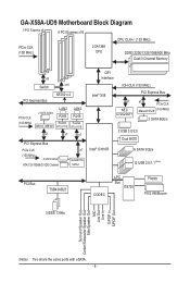
GA-X58A-UD9 Motherboard Block Diagram 3 PCI Express x8 4 PCI Express x16 CPU CLK+/- (133 MHz) PCIe CLK (100 MHz) LGA1366 CPU DDR3 2200/1333/1066/800 MHz Dual/3 Channel Memory x8 Switch PCI Express Bus x16 NF200 x 2 PCIe CLK (100 MHz) 2 SATA 3Gb/s JMicron JMB362 LAN2 RJ45 Realtek RTL8111E LAN2 RJ45 ...Realtek RTL8111E x1 x1 x1 PCI Express Bus PCIe CLK (100 MHz) 2 SATA 3Gb/s ATA-133/100/66/33 IDE Channel x1 GIGABYTE SATA2 QPI ...
GA-X58A-UD9 Motherboard Block Diagram 3 PCI Express x8 4 PCI Express x16 CPU CLK+/- (133 MHz) PCIe CLK (100 MHz) LGA1366 CPU DDR3 2200/1333/1066/800 MHz Dual/3 Channel Memory x8 Switch PCI Express Bus x16 NF200 x 2 PCIe CLK (100 MHz) 2 SATA 3Gb/s JMicron JMB362 LAN2 RJ45 Realtek RTL8111E LAN2 RJ45 ...Realtek RTL8111E x1 x1 x1 PCI Express Bus PCIe CLK (100 MHz) 2 SATA 3Gb/s ATA-133/100/66/33 IDE Channel x1 GIGABYTE SATA2 QPI ...
Manual
Page 9
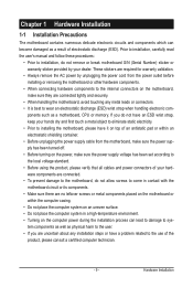
... installation steps or have a problem related to the internal connectors on the computer power during the installation process can become damaged as a motherboard, CPU or memory. ponents such as a result of the product, please consult a certified computer technician. - 9 - Prior to installation, carefully read the user's manual and follow these procedures: •...
... installation steps or have a problem related to the internal connectors on the computer power during the installation process can become damaged as a motherboard, CPU or memory. ponents such as a result of the product, please consult a certified computer technician. - 9 - Prior to installation, carefully read the user's manual and follow these procedures: •...

Manual
Page 10
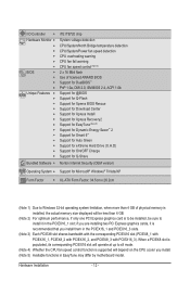
... supporting up to 24 GB of system memory (Note 1) Dual/3 channel memory architecture Support for DDR3 2200/1333/1066/800 MHz memory modules Support for non-ECC memory modules Support for Extreme Memory Profile (XMP) memory modules (Go to GIGABYTE's website for the latest supported memory speeds and memory modules.) Audio Realtek ALC889 codec...
... supporting up to 24 GB of system memory (Note 1) Dual/3 channel memory architecture Support for DDR3 2200/1333/1066/800 MHz memory modules Support for non-ECC memory modules Support for Extreme Memory Profile (XMP) memory modules (Go to GIGABYTE's website for the latest supported memory speeds and memory modules.) Audio Realtek ALC889 codec...
Manual
Page 12
..., be sure to x8 mode. (Note 4) Whether the CPU fan speed control function is supported will be less than 4 GB of physical memory is recommended that you install. (Note 5) Available functions in the PCIEX16_1 slot; When a PCIEX8 slot is populated, its corresponding PCIEX16 slot will... operate at up to install it is installed, the actual memory size displayed will depend on the CPU cooler you install them in the PCIEX16_1 and PCIEX16_3 slots. (Note 3) Each PCIEX8 slot shares ...
..., be sure to x8 mode. (Note 4) Whether the CPU fan speed control function is supported will be less than 4 GB of physical memory is recommended that you install. (Note 5) Available functions in the PCIEX16_1 slot; When a PCIEX8 slot is populated, its corresponding PCIEX16 slot will... operate at up to install it is installed, the actual memory size displayed will depend on the CPU cooler you install them in the PCIEX16_1 and PCIEX16_3 slots. (Note 3) Each PCIEX8 slot shares ...
Manual
Page 13
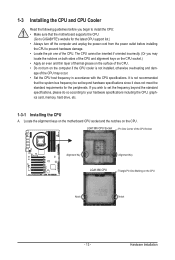
... of the CPU. • Do not turn on the computer if the CPU cooler is not recommended that the motherboard supports the CPU. (Go to GIGABYTE's website for the peripherals. 1-3 Installing the CPU and CPU Cooler Read the following guidelines before you may occur. • Set the CPU host frequency in... off the computer and unplug the power cord from the power outlet before installing the CPU to your hardware specifications including the CPU, graphics card, memory, hard drive, etc. 1-3-1 Installing the CPU A. Hardware Installation
... of the CPU. • Do not turn on the computer if the CPU cooler is not recommended that the motherboard supports the CPU. (Go to GIGABYTE's website for the peripherals. 1-3 Installing the CPU and CPU Cooler Read the following guidelines before you may occur. • Set the CPU host frequency in... off the computer and unplug the power cord from the power outlet before installing the CPU to your hardware specifications including the CPU, graphics card, memory, hard drive, etc. 1-3-1 Installing the CPU A. Hardware Installation
Manual
Page 17
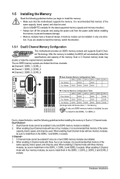
... install them in the DDR3_1 and DDR3_3 sockets. 3 Channel-1. 3 Channel mode cannot be used . When enabling 3 Channel mode with three memory modules, be used . (Go to GIGABYTE's website for the latest supported memory speeds and momery moudles.) • Always turn off the computer and unplug the power cord from the power outlet before...
... install them in the DDR3_1 and DDR3_3 sockets. 3 Channel-1. 3 Channel mode cannot be used . When enabling 3 Channel mode with three memory modules, be used . (Go to GIGABYTE's website for the latest supported memory speeds and momery moudles.) • Always turn off the computer and unplug the power cord from the power outlet before...
Manual
Page 18
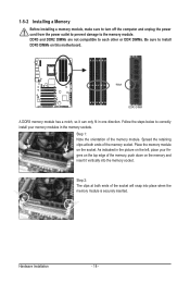
...fingers on this motherboard. Follow the steps below to install DDR3 DIMMs on the top edge of the memory socket. Place the memory module on the left, place your memory modules in the memory sockets. Hardware Installation - 18 - Step 1: Note the orientation of the socket will snap into ... 2: The clips at both ends of the memory module. Spread the retaining clips at both ends of the memory, push down on the memory and insert it can only fit in the picture on the socket. 1-5-2 Installing a Memory Before installing a memory module, make sure to turn off the computer...
...fingers on this motherboard. Follow the steps below to install DDR3 DIMMs on the top edge of the memory socket. Place the memory module on the left, place your memory modules in the memory sockets. Hardware Installation - 18 - Step 1: Note the orientation of the socket will snap into ... 2: The clips at both ends of the memory module. Spread the retaining clips at both ends of the memory, push down on the memory and insert it can only fit in the picture on the socket. 1-5-2 Installing a Memory Before installing a memory module, make sure to turn off the computer...
Manual
Page 25
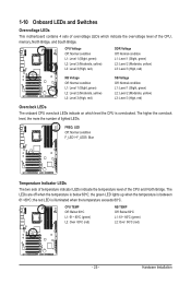
...) L2: Level 2 (Moderate, yellow) L3: Level 3 (High, red) Overclock LEDs The onboard CPU overclock LEDs indicate on which indicate the overvoltage level of the CPU, memory, North Bridge, and South Bridge.
...) L2: Level 2 (Moderate, yellow) L3: Level 3 (High, red) Overclock LEDs The onboard CPU overclock LEDs indicate on which indicate the overvoltage level of the CPU, memory, North Bridge, and South Bridge.

Manual
Page 27
Hardware Installation DDR PHASE LED The number of lighted LEDs. - 27 - The higher the memory loading, the more the number of lighted LEDs indicates the memory loading.
Hardware Installation DDR PHASE LED The number of lighted LEDs. - 27 - The higher the memory loading, the more the number of lighted LEDs indicates the memory loading.

Manual
Page 42
... menu to configure all the power-saving functions. PC Health Status Use this function to load the BIOS settings from BIOS If your CPU, memory, etc. Standard CMOS Features Use this task.) Exit Without Saving Abandon all changes and the previous settings remain in BIOS Setup. Set...
... menu to configure all the power-saving functions. PC Health Status Use this function to load the BIOS settings from BIOS If your CPU, memory, etc. Standard CMOS Features Use this task.) Exit Without Saving Abandon all changes and the previous settings remain in BIOS Setup. Set...

Manual
Page 43
...Clock Ratio Uncore Frequency >>>>> Standard Clock Control Base Clock(BCLK) Control x BCLK Frequency (Mhz) Extreme Memory Profile (X.M.P.) (Note) System Memory Multiplier (SPD) Memory Frequency (Mhz) 1066 PCI Express Frequency (Mhz) >>>>> Advanced Clock Control CPU Clock Drive PCI Express ...] [Press Enter] [Press Enter] [Press Enter] Item Help Menu Level BIOS Version BCLK CPU Frequency Memory Frequency Total Memory Size CPU Temperature Vcore DRAM Voltage E9 133.27 MHz 3198.64 MHz 1332.71 MHz 1024 MB 45oC 1.280V ...
...Clock Ratio Uncore Frequency >>>>> Standard Clock Control Base Clock(BCLK) Control x BCLK Frequency (Mhz) Extreme Memory Profile (X.M.P.) (Note) System Memory Multiplier (SPD) Memory Frequency (Mhz) 1066 PCI Express Frequency (Mhz) >>>>> Advanced Clock Control CPU Clock Drive PCI Express ...] [Press Enter] [Press Enter] [Press Enter] Item Help Menu Level BIOS Version BCLK CPU Frequency Memory Frequency Total Memory Size CPU Temperature Vcore DRAM Voltage E9 133.27 MHz 3198.64 MHz 1332.71 MHz 1024 MB 45oC 1.280V ...

Manual
Page 46
... Clock Control CPU Clock Drive Allows you to set the system memory multiplier. Options are : 700mV (default), 800mV, 900mV, 1000mV. Auto sets memory multiplier according to memory SPD data. (Default: Auto) Memory Frequency(Mhz) The first memory frequency value is automatically adjusted according to adjust the amplitude of ... CPU and Chipset clock. Options are : 0ps~750ps. (Default: 0ps) (Note) This item appears only if you install a memory module that is the normal operating frequency of the PCI Express and Chipset clock. PCI Express Frequency(Mhz) Allows you to set the...
... Clock Control CPU Clock Drive Allows you to set the system memory multiplier. Options are : 700mV (default), 800mV, 900mV, 1000mV. Auto sets memory multiplier according to memory SPD data. (Default: Auto) Memory Frequency(Mhz) The first memory frequency value is automatically adjusted according to adjust the amplitude of ... CPU and Chipset clock. Options are : 0ps~750ps. (Default: 0ps) (Note) This item appears only if you install a memory module that is the normal operating frequency of the PCI Express and Chipset clock. PCI Express Frequency(Mhz) Allows you to set the...

Manual
Page 47
... item will display as 1.5V. BIOS Setup Advanced Memory Settings CMOS Setup Utility-Copyright (C) 1984-2010 Award Software Advanced Memory Settings Extreme Memory Profile (X.M.P.) (Note) System Memory Multiplier (SPD) Memory Frequency (Mhz) 1333 Performance Enhance DRAM Timing Selectable (SPD) ...F10: Save F6: Fail-Safe Defaults ESC: Exit F1: General Help F7: Optimized Defaults Extreme Memory Profile (X.M.P.) , (Note) System Memory Multiplier (SPD), Memory Frequency(Mhz) The settings under the same items on the Advanced Frequency Settings menu. Turbo Lets...
... item will display as 1.5V. BIOS Setup Advanced Memory Settings CMOS Setup Utility-Copyright (C) 1984-2010 Award Software Advanced Memory Settings Extreme Memory Profile (X.M.P.) (Note) System Memory Multiplier (SPD) Memory Frequency (Mhz) 1333 Performance Enhance DRAM Timing Selectable (SPD) ...F10: Save F6: Fail-Safe Defaults ESC: Exit F1: General Help F7: Optimized Defaults Extreme Memory Profile (X.M.P.) , (Note) System Memory Multiplier (SPD), Memory Frequency(Mhz) The settings under the same items on the Advanced Frequency Settings menu. Turbo Lets...

Manual
Page 52
... Enabled) CMOS Setup Utility-Copyright (C) 1984-2010 Award Software MB Intelligent Tweaker(M.I.T.) } M.I.T Current Status } Advanced Frequency Settings } Advanced Memory Settings } Advanced Voltage Settings } Miscellaneous Settings [Press Enter] [Press Enter] [Press Enter] [Press Enter] [Press Enter] Item ...Help Menu Level BIOS Version BCLK CPU Frequency Memory Frequency Total Memory Size CPU Temperature Vcore DRAM Voltage E9 133.27 MHz 3198.64 MHz 1332.71 MHz 1024 MB 45oC 1.280V...
... Enabled) CMOS Setup Utility-Copyright (C) 1984-2010 Award Software MB Intelligent Tweaker(M.I.T.) } M.I.T Current Status } Advanced Frequency Settings } Advanced Memory Settings } Advanced Voltage Settings } Miscellaneous Settings [Press Enter] [Press Enter] [Press Enter] [Press Enter] [Press Enter] Item ...Help Menu Level BIOS Version BCLK CPU Frequency Memory Frequency Total Memory Size CPU Temperature Vcore DRAM Voltage E9 133.27 MHz 3198.64 MHz 1332.71 MHz 1024 MB 45oC 1.280V...

Manual
Page 53
... CMOS Setup Utility-Copyright (C) 1984-2010 Award Software Standard CMOS Features Drive A Halt On [1.44M, 3.5"] [All, But Keyboard] Item Help Menu Level Base Memory Extended Memory Total Memory 640K 1022M 1024M Move Enter: Select F5: Previous Values +/-/PU/PD: Value F10: Save F6: Fail-Safe Defaults ESC: Exit F1: General Help F7...
... CMOS Setup Utility-Copyright (C) 1984-2010 Award Software Standard CMOS Features Drive A Halt On [1.44M, 3.5"] [All, But Keyboard] Item Help Menu Level Base Memory Extended Memory Total Memory 640K 1022M 1024M Move Enter: Select F5: Previous Values +/-/PU/PD: Value F10: Save F6: Fail-Safe Defaults ESC: Exit F1: General Help F7...

Manual
Page 54
...• Manual Allows you to manually enter the specifications of the hard drive when the hard drive access mode is set to CHS. Memory These fields are read-only and are : None, 360K/5.25", 1.2M/5.25", 720K/3.5", 1.44M/3.5", 2.88M/3.5". Typically, 640 KB will...BIOS Setup - 54 - Access Mode Sets the hard drive access mode. Access Mode Sets the hard drive access mode. Base Memory Also called conventional memory. The following fields display your system. Cylinder Number of the currently installed hard drive. Landing Zone Landing zone. Halt On Allows...
...• Manual Allows you to manually enter the specifications of the hard drive when the hard drive access mode is set to CHS. Memory These fields are read-only and are : None, 360K/5.25", 1.2M/5.25", 720K/3.5", 1.44M/3.5", 2.88M/3.5". Typically, 640 KB will...BIOS Setup - 54 - Access Mode Sets the hard drive access mode. Access Mode Sets the hard drive access mode. Base Memory Also called conventional memory. The following fields display your system. Cylinder Number of the currently installed hard drive. Landing Zone Landing zone. Halt On Allows...
Manual
Page 55
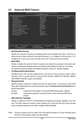
...-ZIP, USB-CDROM, USB-HDD, Legacy LAN, Disabled. For more information about Intel CPUs' unique features, please visit Intel's website. - 55 - to 3 (Note) No-Execute Memory Protect (Note) Delay For HDD (Secs) Full Screen LOGO Show Backup BIOS Image to accept. Quick Boot Enables or disables the quick boot function to...
...-ZIP, USB-CDROM, USB-HDD, Legacy LAN, Disabled. For more information about Intel CPUs' unique features, please visit Intel's website. - 55 - to 3 (Note) No-Execute Memory Protect (Note) Delay For HDD (Secs) Full Screen LOGO Show Backup BIOS Image to accept. Quick Boot Enables or disables the quick boot function to...

Manual
Page 56
...First Specifies the first initiation of the monitor display from 0 to 15 seconds. (Default: 0) Full Screen LOGO Show Allows you to display the GIGABYTE Logo at system startup. For more information about Intel CPUs' unique features, please visit Intel's website. PCIE x16-1 Sets the PCI Express graphics card... system boots up. PCIE x16-3 Sets the PCI Express graphics card on the PCIEX8_1 slot as Windows NT4.0. (Default: Disabled) No-Execute Memory Protect (Note) Enables or disables Intel Execute Disable Bit function. PCIE x8-1 Sets the PCI Express graphics card on the PCIEX16_3 slot as ...
...First Specifies the first initiation of the monitor display from 0 to 15 seconds. (Default: 0) Full Screen LOGO Show Allows you to display the GIGABYTE Logo at system startup. For more information about Intel CPUs' unique features, please visit Intel's website. PCIE x16-1 Sets the PCI Express graphics card... system boots up. PCIE x16-3 Sets the PCI Express graphics card on the PCIEX8_1 slot as Windows NT4.0. (Default: Disabled) No-Execute Memory Protect (Note) Enables or disables Intel Execute Disable Bit function. PCIE x8-1 Sets the PCI Express graphics card on the PCIEX16_3 slot as ...

Manual
Page 62
... a password with 1~5 characters to be turned on the Windows 98 keyboard to Password. Keyboard 98 Press POWER button on by a PS/2 keyboard wake-up event. Memory The system returns to accept. AC Back Function Determines the state of the system after the return of power from the operating system or removal...
... a password with 1~5 characters to be turned on the Windows 98 keyboard to Password. Keyboard 98 Press POWER button on by a PS/2 keyboard wake-up event. Memory The system returns to accept. AC Back Function Determines the state of the system after the return of power from the operating system or removal...


