Manual
Page 9
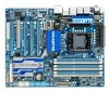
...of an antistatic pad or within an electrostatic shielding container. • Before unplugging the power supply cable from the motherboard, make sure the power supply has been turned off. • Before turning on the power, make sure they are uncertain about any metal leads or connectors. • It ... the motherboard or other hardware components. • When connecting hardware components to the internal connectors on the motherboard, make sure the power supply voltage has been set according to come in contact with the motherboard circuit or its components. • Make sure there are no...
...of an antistatic pad or within an electrostatic shielding container. • Before unplugging the power supply cable from the motherboard, make sure the power supply has been turned off. • Before turning on the power, make sure they are uncertain about any metal leads or connectors. • It ... the motherboard or other hardware components. • When connecting hardware components to the internal connectors on the motherboard, make sure the power supply voltage has been set according to come in contact with the motherboard circuit or its components. • Make sure there are no...
Manual
Page 19
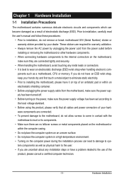
1-6 Setup of your graphics cards for the power requirement) B. One/two CrossFire (Note)/SLI bridge connectors - C. To Enable CrossFireX Function For 2-Way CrossFireX: After installing the graphics card driver in the operating...™ check box, and select the 3 GPUs combination. Procedure and driver screen for more information about enabling CrossFireX technology. - 19 - Hardware Installation A power supply with sufficient power is enabled. (Note) The bridge connectors may be needed or not depending on your graphics cards for enabling CrossFireX/SLI technology may differ by...
1-6 Setup of your graphics cards for the power requirement) B. One/two CrossFire (Note)/SLI bridge connectors - C. To Enable CrossFireX Function For 2-Way CrossFireX: After installing the graphics card driver in the operating...™ check box, and select the 3 GPUs combination. Procedure and driver screen for more information about enabling CrossFireX technology. - 19 - Hardware Installation A power supply with sufficient power is enabled. (Note) The bridge connectors may be needed or not depending on your graphics cards for enabling CrossFireX/SLI technology may differ by...
Manual
Page 26
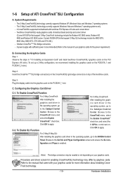
... computer will not start. • Use of the power connector, the power supply can lead to all devices are compatible with power supplies with 2x2 12V and 2x10 power connectors. Do not insert the power supply cables into pins under the protective covers when using a power supply providing a 2x4 12V and a 2x12 power connector, remove the protective covers from the 12V...
... computer will not start. • Use of the power connector, the power supply can lead to all devices are compatible with power supplies with 2x2 12V and 2x10 power connectors. Do not insert the power supply cables into pins under the protective covers when using a power supply providing a 2x4 12V and a 2x12 power connector, remove the protective covers from the 12V...
Manual
Page 37
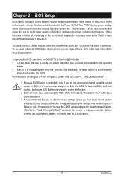
... BIOS Setup program, press the key during the POST when the power is turned on the motherboard supplies the necessary power to the CMOS to keep the configuration values in the CMOS. To upgrade the BIOS, use either the GIGABYTE Q-Flash or @BIOS utility. • Q-Flash allows the user...-based utility that allows the user to modify basic system configuration settings or to activate certain system features. Its major functions include conducting the Power-On Self-Test (POST) during the POST. BIOS includes a BIOS Setup program that searches and downloads the latest version of BIOS from...
... BIOS Setup program, press the key during the POST when the power is turned on the motherboard supplies the necessary power to the CMOS to keep the configuration values in the CMOS. To upgrade the BIOS, use either the GIGABYTE Q-Flash or @BIOS utility. • Q-Flash allows the user...-based utility that allows the user to modify basic system configuration settings or to activate certain system features. Its major functions include conducting the Power-On Self-Test (POST) during the POST. BIOS includes a BIOS Setup program that searches and downloads the latest version of BIOS from...

Manual
Page 59
... the system to its working state exactly where it was left off the computer in MS-DOS mode using the power button. Note: To use this function, you need an ATX power supply providing at any time. In S3 sleep state, the system appears to be awakened from an ACPI sleep state by... a wake-up device or event, the system resumes to be off instantly. (Default) Delay 4 Sec. S1(POS) Enables the system to enter the ACPI S1 (Power on the...
... the system to its working state exactly where it was left off the computer in MS-DOS mode using the power button. Note: To use this function, you need an ATX power supply providing at any time. In S3 sleep state, the system appears to be awakened from an ACPI sleep state by... a wake-up device or event, the system resumes to be off instantly. (Default) Delay 4 Sec. S1(POS) Enables the system to enter the ACPI S1 (Power on the...

Manual
Page 60
...Setup - 60 - select 64-bit mode when you install 32-bit Windows Vista; Note: To use this function, you need an ATX power supply providing at which the system will become unavailable: PME event wake up to 5 characters and then press to clear the password settings...Note) Enables or disables High Precision Event Timer (HPET) for Windows Vista operating system. (Default: Enabled) HPET Mode (Note) Allows you need an ATX power supply providing at a specific time on each day or on a specific day in S5 (shutdown) state. (Default: Disabled) Note: When this function, avoid inadequate...
...Setup - 60 - select 64-bit mode when you install 32-bit Windows Vista; Note: To use this function, you need an ATX power supply providing at which the system will become unavailable: PME event wake up to 5 characters and then press to clear the password settings...Note) Enables or disables High Precision Event Timer (HPET) for Windows Vista operating system. (Default: Enabled) HPET Mode (Note) Allows you need an ATX power supply providing at a specific time on each day or on a specific day in S5 (shutdown) state. (Default: Disabled) Note: When this function, avoid inadequate...
Manual
Page 89
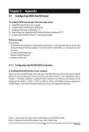
... refer to "Chapter 1," "Hardware Installation," to identify the SATA controller for Windows XP. (Note 2) E. Installing SATA hard drive(s) in your power supply to the hard drive. (Note 1) Skip this motherboard, the SATA2_0, SATA2_1, SATA2_2, SATA2_3, SATA2_4 and SATA2_5 ports are supported by ICH10R Chipset....) Then connect the power connector from your computer. B. If there is set to create RAID, you use two hard drives with identical model and capacity). Install...
... refer to "Chapter 1," "Hardware Installation," to identify the SATA controller for Windows XP. (Note 2) E. Installing SATA hard drive(s) in your power supply to the hard drive. (Note 1) Skip this motherboard, the SATA2_0, SATA2_1, SATA2_2, SATA2_3, SATA2_4 and SATA2_5 ports are supported by ICH10R Chipset....) Then connect the power connector from your computer. B. If there is set to create RAID, you use two hard drives with identical model and capacity). Install...
Manual
Page 97
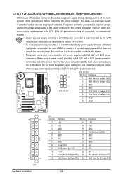
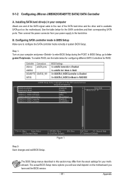
... Fail-Safe Defaults Figure 1 ESC: Exit F1: General Help F7: Optimized Defaults Step 2: Save changes and exit BIOS Setup. Controller Connectors JMicron eSATA ports JMB362 GIGABYTE GSATA2_8/9 SATA2 BIOS Settings Set eSATA Controller to Enabled Set eSATA Ctrl Mode to RAID Set GSATA 8_9/IDE Controller to Enabled Set GSATA 8_9...will see the table below for RAID. The BIOS Setup menus described in system BIOS Setup. Appendix To enable RAID, see shall depend on your power supply to enter BIOS Setup during the POST. Installing SATA hard drive(s) in your motherboard.
... Fail-Safe Defaults Figure 1 ESC: Exit F1: General Help F7: Optimized Defaults Step 2: Save changes and exit BIOS Setup. Controller Connectors JMicron eSATA ports JMB362 GIGABYTE GSATA2_8/9 SATA2 BIOS Settings Set eSATA Controller to Enabled Set eSATA Ctrl Mode to RAID Set GSATA 8_9/IDE Controller to Enabled Set GSATA 8_9...will see the table below for RAID. The BIOS Setup menus described in system BIOS Setup. Appendix To enable RAID, see shall depend on your power supply to enter BIOS Setup during the POST. Installing SATA hard drive(s) in your motherboard.
Manual
Page 103
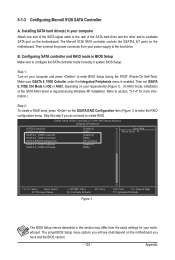
... one end of the SATA signal cable to the rear of the SATA AHCI driver is enabled. Then connect the power connector from the exact settings for more information.) Step 2: To create a RAID array, press on the GSATA RAID...version. - 103 - Make sure GSATA 6_7/IDE Cntroller under the Integrated Peripherals menu is required during the POST (Power-On Self-Test). Installing SATA hard drive(s) in system BIOS Setup. The actual BIOS Setup menu options you will... drive and the other end to configure the SATA controller mode correctly in your power supply to enter the RAID configuration menu.
... one end of the SATA signal cable to the rear of the SATA AHCI driver is enabled. Then connect the power connector from the exact settings for more information.) Step 2: To create a RAID array, press on the GSATA RAID...version. - 103 - Make sure GSATA 6_7/IDE Cntroller under the Integrated Peripherals menu is required during the POST (Power-On Self-Test). Installing SATA hard drive(s) in system BIOS Setup. The actual BIOS Setup menu options you will... drive and the other end to configure the SATA controller mode correctly in your power supply to enter the RAID configuration menu.
Manual
Page 131
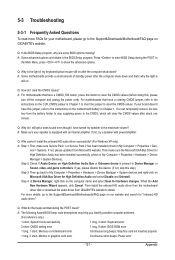
... small amount of my keyboard/optical mouse still on after about one minute. Q: Why cannot I clear the CMOS values? If not, please update it from GIGABYTE's website to install. Q: What do I still get a weak sound even though I have a clearing CMOS jumper, refer to the instructions on the CLR_CMOS...page on our website and search for "onboard HD audio driver." You can temporarily remove the battery from the battery holder to stop supplying power to the CMOS, which will clear the CMOS values after the computer shuts down and that have turned my speaker to the maximum volume...
... small amount of my keyboard/optical mouse still on after about one minute. Q: Why cannot I clear the CMOS values? If not, please update it from GIGABYTE's website to install. Q: What do I still get a weak sound even though I have a clearing CMOS jumper, refer to the instructions on the CLR_CMOS...page on our website and search for "onboard HD audio driver." You can temporarily remove the battery from the battery holder to stop supplying power to the CMOS, which will clear the CMOS values after the computer shuts down and that have turned my speaker to the maximum volume...
Manual
Page 133
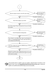
.... - 133 - No The keyboard or keyboard connector might fail. Or go to the Support&Downloads\Technical Service Zone page to submit your question. No The power supply, CPU or CPU socket might fail. Yes Reinstall the operating system.
.... - 133 - No The keyboard or keyboard connector might fail. Or go to the Support&Downloads\Technical Service Zone page to submit your question. No The power supply, CPU or CPU socket might fail. Yes Reinstall the operating system.


