Manual
Page 7
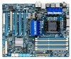
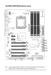
GA-X58A-UD3R Motherboard Layout KB_MS R_SPDIF ATX_12V_2X CMOS_SW USB_1394_ESATA_2 USB_1394_ESATA_1 CPU_FAN CPU Voltage L1/2/3 CPU TEMP L1/2 LGA1366 FREQ. For a longer expansion card, use other expansion slots. - 7 - LED PHASE LED DDR Voltage LED PWR_FAN GA-X58A-UD3R R_USB ATX USB30_LAN JMicron JMB362... SPDIF_O PCIEX8_2 M_BIOS B_BIOS DDR3_2 DDR3_1 Intel® X58 SYS_FAN1 NB Voltage L1/2/3 PCIEX16_1 PCIEX8_1 PCIEX16_2 SB Voltage L1/2/3 BAT Intel® ICH10R Marvell 9128 SYS_FAN3 TSB43AB23 SYS_FAN2 F_USB2 GIGABYTE SATA2 F_PANEL SATA2_1 SATA2_0 SATA2_3 SATA2_2 SATA2_5...
GA-X58A-UD3R Motherboard Layout KB_MS R_SPDIF ATX_12V_2X CMOS_SW USB_1394_ESATA_2 USB_1394_ESATA_1 CPU_FAN CPU Voltage L1/2/3 CPU TEMP L1/2 LGA1366 FREQ. For a longer expansion card, use other expansion slots. - 7 - LED PHASE LED DDR Voltage LED PWR_FAN GA-X58A-UD3R R_USB ATX USB30_LAN JMicron JMB362... SPDIF_O PCIEX8_2 M_BIOS B_BIOS DDR3_2 DDR3_1 Intel® X58 SYS_FAN1 NB Voltage L1/2/3 PCIEX16_1 PCIEX8_1 PCIEX16_2 SB Voltage L1/2/3 BAT Intel® ICH10R Marvell 9128 SYS_FAN3 TSB43AB23 SYS_FAN2 F_USB2 GIGABYTE SATA2 F_PANEL SATA2_1 SATA2_0 SATA2_3 SATA2_2 SATA2_5...

Manual
Page 25
... (500W or greater). Hardware Installation Before connecting the power connector, first make sure the power supply is turned off and all the components on the motherboard. Connect the power supply cable to an unstable or unbootable system. 8 4 5 1 ATX_12V_2X ATX_12V_2X: Pin No. Definition 1 GND (Only for 2x4-pin... +12V 8 +12V 12 24 1 13 ATX ATX: Pin No. 1 2 3 4 5 6 7 8 9 10 11 12 Definition Pin No. 3.3V 13 3.3V 14 GND 15 +5V 16 GND 17 +5V 18 GND 19 Power Good 20 5VSB (stand by the CPU manufacturer when using an Intel Extreme Edition CPU (130W). • To ...
... (500W or greater). Hardware Installation Before connecting the power connector, first make sure the power supply is turned off and all the components on the motherboard. Connect the power supply cable to an unstable or unbootable system. 8 4 5 1 ATX_12V_2X ATX_12V_2X: Pin No. Definition 1 GND (Only for 2x4-pin... +12V 8 +12V 12 24 1 13 ATX ATX: Pin No. 1 2 3 4 5 6 7 8 9 10 11 12 Definition Pin No. 3.3V 13 3.3V 14 GND 15 +5V 16 GND 17 +5V 18 GND 19 Power Good 20 5VSB (stand by the CPU manufacturer when using an Intel Extreme Edition CPU (130W). • To ...


