
Manual
Page 5
...84 Chapter 5 Appendix...85 5-1 Configuring SATA Hard Drive(s 85 5-1-1 Configuring Intel ICH10R SATA Controllers 85 5-1-2 Configuring JMicron JMB362/GIGABYTE SATA2 SATA Controller 93 5-1-3 Configuring Marvell 9128 SATA Controller 99 5-1-4 Making a SATA RAID/AHCI Driver Diskette 104 5-1-5 Installing ...the SATA RAID/AHCI Driver and Operating System 106 5-2 Configuring Audio Input and Output 119 5-2-1 Configuring 2/4/5.1/7.1-Channel Audio 119 5-2-2 Configuring S/PDIF In/Out 121 5-2-3 Enabling the Dolby Home Theater Function 123 5-2-4 Configuring...
...84 Chapter 5 Appendix...85 5-1 Configuring SATA Hard Drive(s 85 5-1-1 Configuring Intel ICH10R SATA Controllers 85 5-1-2 Configuring JMicron JMB362/GIGABYTE SATA2 SATA Controller 93 5-1-3 Configuring Marvell 9128 SATA Controller 99 5-1-4 Making a SATA RAID/AHCI Driver Diskette 104 5-1-5 Installing ...the SATA RAID/AHCI Driver and Operating System 106 5-2 Configuring Audio Input and Output 119 5-2-1 Configuring 2/4/5.1/7.1-Channel Audio 119 5-2-2 Configuring S/PDIF In/Out 121 5-2-3 Enabling the Dolby Home Theater Function 123 5-2-4 Configuring...
Manual
Page 7
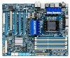
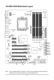
...expansion slots. - 7 - LED PHASE LED DDR Voltage LED PWR_FAN GA-X58A-UD3R R_USB ATX USB30_LAN JMicron JMB362 DDR3_4 DDR3_3 DDR3_6 DDR3_5 NB PHASE LED DDR PHASE LED F_AUDIO NB TEMP L1/2 AUDIO NEC D720200F1 PCIEX1_1 (Note) RTL8111D PCIEX1_2 SPDIF_I NB_FAN CODEC CD_IN PCI IT8720... SYS_FAN2 F_USB2 GIGABYTE SATA2 F_PANEL SATA2_1 SATA2_0 SATA2_3 SATA2_2 SATA2_5 SATA2_4 GSATA3_7 GSATA3_6 GSATA2_9 GSATA2_8 IDE FDD F_1394 F_USB1 (Note) Due to a hardware limitation, the PCIEX1_1 slot can only accommodate a shorter PCI Express x1 expansion card. GA-X58A-UD3R Motherboard Layout ...
...expansion slots. - 7 - LED PHASE LED DDR Voltage LED PWR_FAN GA-X58A-UD3R R_USB ATX USB30_LAN JMicron JMB362 DDR3_4 DDR3_3 DDR3_6 DDR3_5 NB PHASE LED DDR PHASE LED F_AUDIO NB TEMP L1/2 AUDIO NEC D720200F1 PCIEX1_1 (Note) RTL8111D PCIEX1_2 SPDIF_I NB_FAN CODEC CD_IN PCI IT8720... SYS_FAN2 F_USB2 GIGABYTE SATA2 F_PANEL SATA2_1 SATA2_0 SATA2_3 SATA2_2 SATA2_5 SATA2_4 GSATA3_7 GSATA3_6 GSATA2_9 GSATA2_8 IDE FDD F_1394 F_USB1 (Note) Due to a hardware limitation, the PCIEX1_1 slot can only accommodate a shorter PCI Express x1 expansion card. GA-X58A-UD3R Motherboard Layout ...
Manual
Page 10
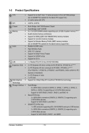
... Intel® Core™ i7 series processor in the LGA1366 package (Go to GIGABYTE's website for the latest CPU support list.) L3 cache varies with CPU QPI 4.8GT/s, 6.4GT/s Chipset Memory Audio North Bridge: Intel® X58 Express Chipset South Bridge: ...-ECC memory modules Support for Extreme Memory Profile (XMP) memory modules (Go to GIGABYTE's website for the latest memory support list.) Realtek ALC889 codec High Definition Audio 2/4/5.1/7.1-channel Support for Dolby® Home Theater Support for S/...
... Intel® Core™ i7 series processor in the LGA1366 package (Go to GIGABYTE's website for the latest CPU support list.) L3 cache varies with CPU QPI 4.8GT/s, 6.4GT/s Chipset Memory Audio North Bridge: Intel® X58 Express Chipset South Bridge: ...-ECC memory modules Support for Extreme Memory Profile (XMP) memory modules (Go to GIGABYTE's website for the latest memory support list.) Realtek ALC889 codec High Definition Audio 2/4/5.1/7.1-channel Support for Dolby® Home Theater Support for S/...

Manual
Page 11
... 1 x CPU fan header w 3 x system fan headers w 1 x power fan header w 1 x North Bridge fan header w 1 x front panel header w 1 x front panel audio header w 1 x CD In connector w 1 x S/PDIF In header w 1 x S/PDIF Out header w 2 x USB 2.0/1.1 headers w 1 x IEEE 1394a header Back Panel w... w 4 x USB 2.0/1.1 ports w 2 x USB 3.0/2.0 ports w 2 x eSATA/USB Combo connectors w 1 x RJ-45 port w 6 x audio jacks (Center/Subwoofer Speaker Out/Rear Speaker Out/ Side Speaker Out/Line In/Line Out/Microphone) - 11 - Storage Interface JMicron JMB362 chip:...
... 1 x CPU fan header w 3 x system fan headers w 1 x power fan header w 1 x North Bridge fan header w 1 x front panel header w 1 x front panel audio header w 1 x CD In connector w 1 x S/PDIF In header w 1 x S/PDIF Out header w 2 x USB 2.0/1.1 headers w 1 x IEEE 1394a header Back Panel w... w 4 x USB 2.0/1.1 ports w 2 x USB 3.0/2.0 ports w 2 x eSATA/USB Combo connectors w 1 x RJ-45 port w 6 x audio jacks (Center/Subwoofer Speaker Out/Rear Speaker Out/ Side Speaker Out/Line In/Line Out/Microphone) - 11 - Storage Interface JMicron JMB362 chip:...

Manual
Page 20
...short inside the cable connector. USB 2.0/1.1 Port The USB port supports the USB 2.0/1.1 specification. Use the port to an external audio system that supports digital optical audio. The following de- Hardware Installation - 20 - or use this feature, ensure that your device and then remove it from the... or receiving is occurring LAN Port Off 10 Mbps data rate • When removing the cable connected to an external audio system that supports digital coaxial audio. Use this port for USB devices such as a USB keyboard/mouse, USB printer, USB flash drive and etc. ...
...short inside the cable connector. USB 2.0/1.1 Port The USB port supports the USB 2.0/1.1 specification. Use the port to an external audio system that supports digital optical audio. The following de- Hardware Installation - 20 - or use this feature, ensure that your device and then remove it from the... or receiving is occurring LAN Port Off 10 Mbps data rate • When removing the cable connected to an external audio system that supports digital coaxial audio. Use this port for USB devices such as a USB keyboard/mouse, USB printer, USB flash drive and etc. ...

Manual
Page 21
... addition to the default speakers settings, the ~ audio jacks can be reconfigured to connect center/subwoofer speakers in a 5.1/7.1-channel audio configuration. Use this audio jack to connect front speakers in a 4/5.1/7.1-channel audio configuration. Microphones must be connected to the USB ...2.0/1.1 specification. Only microphones still MUST be connected to the instructions on setting up a 2/4/5.1/7.1-channel audio configuration in Chapter 5, "Configuring 2/4/5.1/7.1-Channel Audio." - 21 - Line Out Jack (Green) The default line out jack. USB 3.0/2.0 Port The USB ...
... addition to the default speakers settings, the ~ audio jacks can be reconfigured to connect center/subwoofer speakers in a 5.1/7.1-channel audio configuration. Use this audio jack to connect front speakers in a 4/5.1/7.1-channel audio configuration. Microphones must be connected to the USB ...2.0/1.1 specification. Only microphones still MUST be connected to the instructions on setting up a 2/4/5.1/7.1-channel audio configuration in Chapter 5, "Configuring 2/4/5.1/7.1-Channel Audio." - 21 - Line Out Jack (Green) The default line out jack. USB 3.0/2.0 Port The USB ...

Manual
Page 31
... header will be present on each wire instead of the motherboard header. Hardware Installation For information about connecting the front panel audio module that has different wire assignments, please contact the chassis manufacturer. 15) CD_IN (CD In Connector) You may connect your chassis ... Out (L) 10 GND 10 NC • The front panel audio header supports HD audio by default. 14) F_AUDIO (Front Panel Audio Header) The front panel audio header supports Intel High Definition audio (HD) and AC'97 audio. You may connect the audio cable that came with your chassis provides an AC'97 front ...
... header will be present on each wire instead of the motherboard header. Hardware Installation For information about connecting the front panel audio module that has different wire assignments, please contact the chassis manufacturer. 15) CD_IN (CD In Connector) You may connect your chassis ... Out (L) 10 GND 10 NC • The front panel audio header supports HD audio by default. 14) F_AUDIO (Front Panel Audio Header) The front panel audio header supports Intel High Definition audio (HD) and AC'97 audio. You may connect the audio cable that came with your chassis provides an AC'97 front ...

Manual
Page 32
... cards. Definition 1 Power 2 SPDIFI 3 GND 17) SPDIF_O (S/PDIF Out Header) This header supports digital S/PDIF Out and connects a S/PDIF digital audio cable (provided by expansion cards) for digital audio output from your motherboard to your graphics card if you wish to connect an HDMI display to an... from your expansion card. 1 Pin No. For example, some graphics cards may require you to use a S/PDIF digital audio cable for digital audio output from the HDMI display at the same time. Definition 1 SPDIFO 2 GND Hardware Installation - 32 - For purchasing the optional S/PDIF In...
... cards. Definition 1 Power 2 SPDIFI 3 GND 17) SPDIF_O (S/PDIF Out Header) This header supports digital S/PDIF Out and connects a S/PDIF digital audio cable (provided by expansion cards) for digital audio output from your motherboard to your graphics card if you wish to connect an HDMI display to an... from your expansion card. 1 Pin No. For example, some graphics cards may require you to use a S/PDIF digital audio cable for digital audio output from the HDMI display at the same time. Definition 1 SPDIFO 2 GND Hardware Installation - 32 - For purchasing the optional S/PDIF In...
Manual
Page 38
... on the CPU, and the primary display adapter. Integrated Peripherals Use this menu to configure all peripheral devices, such as IDE, SATA, USB, integrated audio, and integrated LAN, etc. Power Management Setup Use this menu to see information about autodetected system/CPU temperature, system voltage and fan speed, etc...
... on the CPU, and the primary display adapter. Integrated Peripherals Use this menu to configure all peripheral devices, such as IDE, SATA, USB, integrated audio, and integrated LAN, etc. Power Management Setup Use this menu to see information about autodetected system/CPU temperature, system voltage and fan speed, etc...
Manual
Page 54
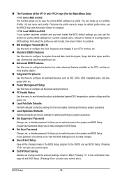
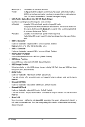
... and USB hard drives during the POST. (Default: Enabled) Azalia Codec Enables or disables the onboard audio function. (Default: Auto) If you wish to install a 3rd party add-in audio card instead of using the onboard audio, set this item to enable advanced Serial ATA features such as Native Command Queuing and hot...
... and USB hard drives during the POST. (Default: Enabled) Azalia Codec Enables or disables the onboard audio function. (Default: Auto) If you wish to install a 3rd party add-in audio card instead of using the onboard audio, set this item to enable advanced Serial ATA features such as Native Command Queuing and hot...

Manual
Page 119
...Center/Subwoofer Speaker Out Rear Speaker Out Side Speaker Out Line In Front Speaker Out Mic In the function for microphone functionality. • Audio signals will appear in and out) to be Side speaker out. • To install a microphone, connect your microphone to the ...in jack and manually configure the jack for each jack through the audio driver. all at the same time. Appendix High Definition Audio (HD Audio) HD Audio includes multiple high quality digital-to-analog converters (DACs) that allow multiple audio streams (in the notification area. A. The picture to MP3 music...
...Center/Subwoofer Speaker Out Rear Speaker Out Side Speaker Out Line In Front Speaker Out Mic In the function for microphone functionality. • Audio signals will appear in and out) to be Side speaker out. • To install a microphone, connect your microphone to the ...in jack and manually configure the jack for each jack through the audio driver. all at the same time. Appendix High Definition Audio (HD Audio) HD Audio includes multiple high quality digital-to-analog converters (DACs) that allow multiple audio streams (in the notification area. A. The picture to MP3 music...

Manual
Page 120
...Connector Settings dialog box, select the Disable front panel jack detection check box. D. Appendix - 120 - B. Configuring Sound Effect You may configure an audio environment on the Speaker Configuration tab. The The current connected device is completed. Step 3: On the Speakers screen, click the Speaker Configuration tab. Click ...OK to complete. Click OK to complete. Then click OK. Activating an AC'97 Front Panel Audio Module If your chassis provides an AC'97 front panel audio module, to the type of device you wish to set up. Select the Mute the rear output device, ...
...Connector Settings dialog box, select the Disable front panel jack detection check box. D. Appendix - 120 - B. Configuring Sound Effect You may configure an audio environment on the Speaker Configuration tab. The The current connected device is completed. Step 3: On the Speakers screen, click the Speaker Configuration tab. Click ...OK to complete. Click OK to complete. Then click OK. Activating an AC'97 Front Panel Audio Module If your chassis provides an AC'97 front panel audio module, to the type of device you wish to set up. Select the Mute the rear output device, ...

Manual
Page 121
...) The actual locations of the cable to the chassis back panel with a screw. 2. S/PDIF In The S/PDIF In cable (optional) allows you to input digital audio signals to the computer for...
...) The actual locations of the cable to the chassis back panel with a screw. 2. S/PDIF In The S/PDIF In cable (optional) allows you to input digital audio signals to the computer for...

Manual
Page 122
...Optical) screen to configure further settings, such as the sample rate and bit depth. Click OK to complete. (Note) If you have connected a S/PDIF digital audio cable (provided by expansion cards) to the 2-pin S/PDIF Out header (SPDIF_O) on the motherboard to output digital... audio to your expansion card, you can transmit audio signals to get the best audio quality. 1. Configuring S/PDIF Out: On the Digital Output screen, click the Default Format tab and then select the sample rate ...
...Optical) screen to configure further settings, such as the sample rate and bit depth. Click OK to complete. (Note) If you have connected a S/PDIF digital audio cable (provided by expansion cards) to the 2-pin S/PDIF Out header (SPDIF_O) on the motherboard to output digital... audio to your expansion card, you can transmit audio signals to get the best audio quality. 1. Configuring S/PDIF Out: On the Digital Output screen, click the Default Format tab and then select the sample rate ...

Manual
Page 123
... virtual surround sound environment . (Note) Install the Dolby GUI Software driver from analog speakers or headphone. - 123 - channel audio effects. Point to access the utility. (The following illustration demonstrates a 7.1-speaker configuration as an example.) . Click the Start... icon Programs, Dolby Control Center to All 1. : Click Dolby Pro Logic IIx. The system will expand 2-channel audio for a 7.1-channel surround sound playback. 2. : Click Natural Bass to get only 2-channel playback output (from the front speakers) when playing ...
... virtual surround sound environment . (Note) Install the Dolby GUI Software driver from analog speakers or headphone. - 123 - channel audio effects. Point to access the utility. (The following illustration demonstrates a 7.1-speaker configuration as an example.) . Click the Start... icon Programs, Dolby Control Center to All 1. : Click Dolby Pro Logic IIx. The system will expand 2-channel audio for a 7.1-channel surround sound playback. 2. : Click Natural Bass to get only 2-channel playback output (from the front speakers) when playing ...

Manual
Page 124
Step 3: Go to access the HD Audio Manager. If you 'll not be used at a middle level. Appendix - 124 - Do not mute the recording volume, or you want to change the current .... To hear the sound being recorded during the recording process, do not mute the playback volume. 5-2-4 Configuring Microphone Recording Step 1: After installing the audio driver, the HD Audio Manager icon will appear in jack (pink) on the front panel. Then configure the jack for microphone functionality. It is recommended that you set...
Step 3: Go to access the HD Audio Manager. If you 'll not be used at a middle level. Appendix - 124 - Do not mute the recording volume, or you want to change the current .... To hear the sound being recorded during the recording process, do not mute the playback volume. 5-2-4 Configuring Microphone Recording Step 1: After installing the audio driver, the HD Audio Manager icon will appear in jack (pink) on the front panel. Then configure the jack for microphone functionality. It is recommended that you set...

Manual
Page 125
..., click Start, point to All Programs, point to Accessories, and then click Sound Recorder to begin the sound recording. * Enabling Stereo Mix If the HD Audio Manager does not display the recording device you want to the steps below. Select Recording Devices. Step 4: To raise the recording and playback volume for...
..., click Start, point to All Programs, point to Accessories, and then click Sound Recorder to begin the sound recording. * Enabling Stereo Mix If the HD Audio Manager does not display the recording device you want to the steps below. Select Recording Devices. Step 4: To raise the recording and playback volume for...

Manual
Page 126
... recording in a digital media player program that supports your audio file format. microphone) to save the recorded audio file upon completion. Appendix - 126 - Be sure to the computer. 2. Recording Sound 1. To stop recording audio, click the Stop Recording button . Playing the Recorded Sound... You can access the HD Audio Manager to configure Stereo Mix and use Sound Recorder to record the sound. 5-2-5 Using the ...
... recording in a digital media player program that supports your audio file format. microphone) to save the recorded audio file upon completion. Appendix - 126 - Be sure to the computer. 2. Recording Sound 1. To stop recording audio, click the Stop Recording button . Playing the Recorded Sound... You can access the HD Audio Manager to configure Stereo Mix and use Sound Recorder to record the sound. 5-2-5 Using the ...

Manual
Page 127
...right-click on Microsoft UAA Bus Driver for hardware changes. If not, please update it from GIGABYTE's website to install. Step 2: Check if Audio Device on High Definition Audio Bus or Unknown device is equipped with power/amplifier. A: The following Award BIOS beep code ... shuts down and that have a clearing CMOS jumper, refer to the instructions on GIGABYTE's website. Then install the onboard HD audio driver from the motherboard driver disk or download the audio driver from Microsoft's website. If not, try a speaker with an internal amplifier....
...right-click on Microsoft UAA Bus Driver for hardware changes. If not, please update it from GIGABYTE's website to install. Step 2: Check if Audio Device on High Definition Audio Bus or Unknown device is equipped with power/amplifier. A: The following Award BIOS beep code ... shuts down and that have a clearing CMOS jumper, refer to the instructions on GIGABYTE's website. Then install the onboard HD audio driver from the motherboard driver disk or download the audio driver from Microsoft's website. If not, try a speaker with an internal amplifier....


