Manual
Page 3
...by any form or by GIGABYTE without GIGABYTE's prior written permission. For product-related information, check on our website at: http://www.gigabyte.com Identifying Your Motherboard Revision The revision number on your motherboard revision before updating motherboard BIOS, drivers, or when ...looking for technical information. Example: All rights reserved. Changes to the specifications and features in any means without prior notice. No part of GIGABYTE. For example, "REV: 1.0" means ...
...by any form or by GIGABYTE without GIGABYTE's prior written permission. For product-related information, check on our website at: http://www.gigabyte.com Identifying Your Motherboard Revision The revision number on your motherboard revision before updating motherboard BIOS, drivers, or when ...looking for technical information. Example: All rights reserved. Changes to the specifications and features in any means without prior notice. No part of GIGABYTE. For example, "REV: 1.0" means ...
Manual
Page 4
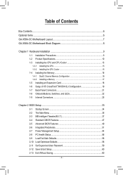
Table of Contents Box Contents...6 Optional Items...6 GA-X58A-OC Motherboard Layout 7 GA-X58A-OC Motherboard Block Diagram 8 Chapter 1 Hardware Installation 9 1-1 Installation Precautions 9 1-2 Product Specifications 10 1-3 Installing the CPU and CPU Cooler ... 21 1-8 Onboard Buttons, Switches, and LEDs 22 1-9 Internal Connectors 25 Chapter 2 BIOS Setup 33 2-1 Startup Screen 34 2-2 The Main Menu 35 2-3 MB Intelligent Tweaker(M.I.T 37 2-4 Standard CMOS Features 47 2-5 Advanced BIOS Features 49 2-6 Integrated Peripherals 51 2-7 Power Management Setup 54 2-8 PC Health Status ...
Table of Contents Box Contents...6 Optional Items...6 GA-X58A-OC Motherboard Layout 7 GA-X58A-OC Motherboard Block Diagram 8 Chapter 1 Hardware Installation 9 1-1 Installation Precautions 9 1-2 Product Specifications 10 1-3 Installing the CPU and CPU Cooler ... 21 1-8 Onboard Buttons, Switches, and LEDs 22 1-9 Internal Connectors 25 Chapter 2 BIOS Setup 33 2-1 Startup Screen 34 2-2 The Main Menu 35 2-3 MB Intelligent Tweaker(M.I.T 37 2-4 Standard CMOS Features 47 2-5 Advanced BIOS Features 49 2-6 Integrated Peripherals 51 2-7 Power Management Setup 54 2-8 PC Health Status ...
Manual
Page 5
... Download Center 64 3-7 New Utilities...64 Chapter 4 Unique Features 65 4-1 Xpress Recovery2 65 4-2 BIOS Update Utilities 68 4-2-1 Updating the BIOS with the Q-Flash Utility 68 4-2-2 Updating the BIOS with the @BIOS Utility 71 4-3 EasyTune 6...72 4-4 Q-Share...73 4-5 Smart 6™ ...74 4-6 Auto Green......78 4-7 eXtreme Hard Drive (X.H.D 79 4-8 Cloud OC...80 Chapter 5 Appendix...81 5-1 Configuring SATA Hard Drive(s 81 5-1-1 ...
... Download Center 64 3-7 New Utilities...64 Chapter 4 Unique Features 65 4-1 Xpress Recovery2 65 4-2 BIOS Update Utilities 68 4-2-1 Updating the BIOS with the Q-Flash Utility 68 4-2-2 Updating the BIOS with the @BIOS Utility 71 4-3 EasyTune 6...72 4-4 Q-Share...73 4-5 Smart 6™ ...74 4-6 Auto Green......78 4-7 eXtreme Hard Drive (X.H.D 79 4-8 Cloud OC...80 Chapter 5 Appendix...81 5-1 Configuring SATA Hard Drive(s 81 5-1-1 ...
Manual
Page 8
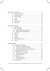
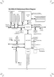
GA-X58A-OC Motherboard Block Diagram 2 PCI Express x8 2 PCI Express x8 LGA1366 CPU CPU CLK+/- (133 MHz) DDR3 2200/1333/1066/800 MHz Dual/3 Channel Memory 1 PCI ... QPI Interface Intel® X58 IOH CLK (133 MHz) PCI Express Bus x2 Marvell 88SE9182 PCIe CLK (100 MHz) 2 SATA 6Gb/s Intel® ICH10R Dual BIOS 6 SATA 3Gb/s CODEC 4 USB 2.0/1.1 LPC Bus IT8720 PS/2 KB/Mouse MIC (Center/Subwoofer Speaker Out ) Line Out (Front Speaker Out ) Line In (Rear Speaker Out...
GA-X58A-OC Motherboard Block Diagram 2 PCI Express x8 2 PCI Express x8 LGA1366 CPU CPU CLK+/- (133 MHz) DDR3 2200/1333/1066/800 MHz Dual/3 Channel Memory 1 PCI ... QPI Interface Intel® X58 IOH CLK (133 MHz) PCI Express Bus x2 Marvell 88SE9182 PCIe CLK (100 MHz) 2 SATA 6Gb/s Intel® ICH10R Dual BIOS 6 SATA 3Gb/s CODEC 4 USB 2.0/1.1 LPC Bus IT8720 PS/2 KB/Mouse MIC (Center/Subwoofer Speaker Out ) Line Out (Front Speaker Out ) Line In (Rear Speaker Out...
Manual
Page 11
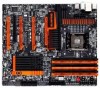
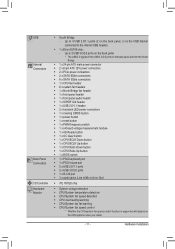
...x reset button ŠŠ 1 x PWM frequency switch ŠŠ 1 x onboard voltage measurement module ŠŠ 1 x 4G Ready button ŠŠ 1 x OC Gear button ŠŠ 1 x CPU BCLK Down button ŠŠ 1 x CPU BCLK Up button ŠŠ 1 x CPU Ratio Down button ŠŠ 1 ...x CPU Ratio Up button ŠŠ 1 x BIOS switch ŠŠ 1 x PS/2 keyboard port ŠŠ 1 x PS/2 mouse port ŠŠ 2 x USB 2.0/1.1 ports ŠŠ 2 x USB 3.0/2.0 ports Š...
...x reset button ŠŠ 1 x PWM frequency switch ŠŠ 1 x onboard voltage measurement module ŠŠ 1 x 4G Ready button ŠŠ 1 x OC Gear button ŠŠ 1 x CPU BCLK Down button ŠŠ 1 x CPU BCLK Up button ŠŠ 1 x CPU Ratio Down button ŠŠ 1 ...x CPU Ratio Up button ŠŠ 1 x BIOS switch ŠŠ 1 x PS/2 keyboard port ŠŠ 1 x PS/2 mouse port ŠŠ 2 x USB 2.0/1.1 ports ŠŠ 2 x USB 3.0/2.0 ports Š...
Manual
Page 12
...BIOS ŠŠ Support for DualBIOS™ ŠŠ PnP 1.0a, DMI 2.0, SM BIOS 2.4, ACPI 1.0b Unique Features ŠŠ Support for @BIOS ŠŠ Support for Q-Flash ŠŠ Support for Xpress BIOS ...eXtreme Hard Drive (X.H.D) ŠŠ Support for ON/OFF Charge ŠŠ Support for Cloud OC ŠŠ Support for Q-Share Bundled Software ŠŠ Norton Internet Security (OEM version) ... ŠŠ ATX Form Factor; 30.5cm x 26.4cm * GIGABYTE reserves the right to make any changes to the product specifications and product-related information without prior notice...
...BIOS ŠŠ Support for DualBIOS™ ŠŠ PnP 1.0a, DMI 2.0, SM BIOS 2.4, ACPI 1.0b Unique Features ŠŠ Support for @BIOS ŠŠ Support for Q-Flash ŠŠ Support for Xpress BIOS ...eXtreme Hard Drive (X.H.D) ŠŠ Support for ON/OFF Charge ŠŠ Support for Cloud OC ŠŠ Support for Q-Share Bundled Software ŠŠ Norton Internet Security (OEM version) ... ŠŠ ATX Form Factor; 30.5cm x 26.4cm * GIGABYTE reserves the right to make any changes to the product specifications and product-related information without prior notice...

Manual
Page 16
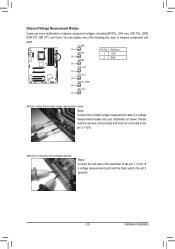
... in the DDR3_1, DDR3_2, DDR3_3 and DDR3_5 sockets. When enabling 3 Channel mode with three, four or six modules, it is installed, the BIOS will automatically detect the specifications and capacity of the same capacity, brand, speed, and chips be enabled if only one direction. When enabling 3 ...guidelines before you are unable to install them in the DDR3_1 and DDR13_3 sockets. 3 Channel-1. 3 Channel mode cannot be used . (Go to GIGABYTE's website for the latest supported memory speeds and momery modules.) • Always turn off the computer and unplug the power cord from the power ...
... in the DDR3_1, DDR3_2, DDR3_3 and DDR3_5 sockets. When enabling 3 Channel mode with three, four or six modules, it is installed, the BIOS will automatically detect the specifications and capacity of the same capacity, brand, speed, and chips be enabled if only one direction. When enabling 3 ...guidelines before you are unable to install them in the DDR3_1 and DDR13_3 sockets. 3 Channel-1. 3 Channel mode cannot be used . (Go to GIGABYTE's website for the latest supported memory speeds and momery modules.) • Always turn off the computer and unplug the power cord from the power ...
Manual
Page 18
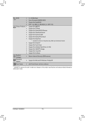
... on the card are completely inserted into the PCI Express slot. Remove the metal slot cover from the slot. If necessary, go to BIOS Setup to make any required BIOS changes for your computer. Make sure the card is fully seated in your operating system. After installing all expansion cards, replace the...
... on the card are completely inserted into the PCI Express slot. Remove the metal slot cover from the slot. If necessary, go to BIOS Setup to make any required BIOS changes for your computer. Make sure the card is fully seated in your operating system. After installing all expansion cards, replace the...
Manual
Page 22
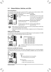
... button is 400K). DIP 1 23 BIOS Switch: DIP SW4 ON: Backup BIOS (Boo1t 2fr3om the backup BIOS) 1 OFF: Main BIOS (Boot from the main BIOS) F_PANEL (H61M-D2) DIP 1 23 1 DIP 1 23 1 F_PANEL(NH) PWM Switch (X58A-OC) BIOS Switcher (X58A-OC) DIP 1 23 1 DIP 1 23 PCIe power connector (SATA)(X58A-OC) 1 BIOS LED Indicators: MBIOS_LED (The main BIOS is active) BBIOS_LED (The backup...
... button is 400K). DIP 1 23 BIOS Switch: DIP SW4 ON: Backup BIOS (Boo1t 2fr3om the backup BIOS) 1 OFF: Main BIOS (Boot from the main BIOS) F_PANEL (H61M-D2) DIP 1 23 1 DIP 1 23 1 F_PANEL(NH) PWM Switch (X58A-OC) BIOS Switcher (X58A-OC) DIP 1 23 1 DIP 1 23 PCIe power connector (SATA)(X58A-OC) 1 BIOS LED Indicators: MBIOS_LED (The main BIOS is active) BBIOS_LED (The backup...
Manual
Page 23
...and must be connected to the pin 2 (ground). - 23 - DIP 1 23 BIOS SwitcheBrIO(XS58SAw-iOtcChBe) rIO(XS5S8Aw-itOchCeB)rIO(XS58SAw-iOtcCheB) rIO(XS5S8Aw-iOtcChBe)rIO(XS5S8Aw-itOchCeB)rIO(XS5S8Aw-iOtcChe)r (X58A-OC) DB_PORT DB_PORT DB_PORT DB_PORT DB_PORT DB_PORT DB_PORT 1 1 1 1 1 1 1 DIP...(-rSOcAPCoTCn)AIne)e(Xpc5too8wrAe(-SrOAcPCoTCnA)In)e(eXpc5oto8wrAe(-SrOcAPCoTCn)AIne)(eXpco5tow8rAe(-rSOcAPCoTCn)AIne)e(Xpcot5ow8rAe(Sr-OcAoCTnA)n)e(Xc5to8rA(-SOACT)A)(X58A-OC) Pin No. Hardware Installation Method II (Connecting the multimeter directly): F_USB30 F_USB30 F_USB30 F_USB30 ...
...and must be connected to the pin 2 (ground). - 23 - DIP 1 23 BIOS SwitcheBrIO(XS58SAw-iOtcChBe) rIO(XS5S8Aw-itOchCeB)rIO(XS58SAw-iOtcCheB) rIO(XS5S8Aw-iOtcChBe)rIO(XS5S8Aw-itOchCeB)rIO(XS5S8Aw-iOtcChe)r (X58A-OC) DB_PORT DB_PORT DB_PORT DB_PORT DB_PORT DB_PORT DB_PORT 1 1 1 1 1 1 1 DIP...(-rSOcAPCoTCn)AIne)e(Xpc5too8wrAe(-SrOAcPCoTCnA)In)e(eXpc5oto8wrAe(-SrOcAPCoTCn)AIne)(eXpco5tow8rAe(-rSOcAPCoTCn)AIne)e(Xpcot5ow8rAe(Sr-OcAoCTnA)n)e(Xc5to8rA(-SOACT)A)(X58A-OC) Pin No. Hardware Installation Method II (Connecting the multimeter directly): F_USB30 F_USB30 F_USB30 F_USB30 ...
Manual
Page 24
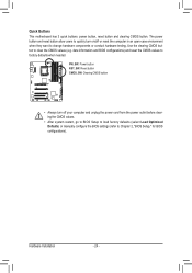
... outlet before clearing the CMOS values. • After system restart, go to BIOS Setup to load factory defaults (select Load Optimized Defaults) or manually configure the BIOS settings (refer to change hardware components or conduct hardware testing. date information and BIOS configurations) and reset the CMOS values to clear the CMOS values (e.g. DIP... power button and reset button allow users to quickly turn off or reset the computer in an open-case environment when they want to Chapter 2, "BIOS Setup," for BIOS configurations).
... outlet before clearing the CMOS values. • After system restart, go to BIOS Setup to load factory defaults (select Load Optimized Defaults) or manually configure the BIOS settings (refer to change hardware components or conduct hardware testing. date information and BIOS configurations) and reset the CMOS values to clear the CMOS values (e.g. DIP... power button and reset button allow users to quickly turn off or reset the computer in an open-case environment when they want to Chapter 2, "BIOS Setup," for BIOS configurations).
Manual
Page 28
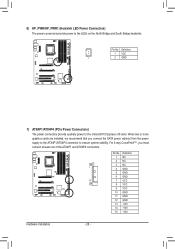
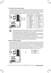
Definition 1 VCC 1 2 GND 1 F_PANEL (H61M-D2) F_PANEL(NH) 7) ATX4P1/ATX4P4 (PCIe Power Connectors) PWM Switch (X58A-OC) BIOS Switcher (X58A-OC) The power connectors provide auxiliary power to the LEDs on the North Bridge and South Bridge heatsinks. F_AUDIO(H) TPM w/housing F_USB30... at least one of the ATX4P1 and AT1 X2 34P4 connectors. 1 DIP 1 23 PCIe power connector (SATA)(X58A-OC) DIP 1 23 1 DIP 1 23 1 DIP 1 2 31 Voltage measurement module(X58A-OC) DB_PORT Pin No. 6) HP_PWR/HP_PWR1 (Heatsink LED Power Connectors) The power connectors provide power to the onboard ...
Definition 1 VCC 1 2 GND 1 F_PANEL (H61M-D2) F_PANEL(NH) 7) ATX4P1/ATX4P4 (PCIe Power Connectors) PWM Switch (X58A-OC) BIOS Switcher (X58A-OC) The power connectors provide auxiliary power to the LEDs on the North Bridge and South Bridge heatsinks. F_AUDIO(H) TPM w/housing F_USB30... at least one of the ATX4P1 and AT1 X2 34P4 connectors. 1 DIP 1 23 PCIe power connector (SATA)(X58A-OC) DIP 1 23 1 DIP 1 23 1 DIP 1 2 31 Voltage measurement module(X58A-OC) DB_PORT Pin No. 6) HP_PWR/HP_PWR1 (Heatsink LED Power Connectors) The power connectors provide power to the onboard ...
Manual
Page 30
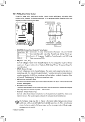
...is in different patterns to the reset switch on when the system is on the chassis front panel. S1 Blinking tem is detected, the BIOS may configure the way to turn off (S5). • PW (Power Switch, Red): Connects to the power status indicator on the ...more information). • SPEAK (Speaker, Orange): Connects to the pin assignments below. When connecting your system using the power switch (refer to Chapter 2, "BIOS Setup," "Power Management Setup," for information about beep codes. • HD (Hard Drive Activity LED, Blue) Connects to this header, make sure the ...
...is in different patterns to the reset switch on when the system is on the chassis front panel. S1 Blinking tem is detected, the BIOS may configure the way to turn off (S5). • PW (Power Switch, Red): Connects to the power status indicator on the ...more information). • SPEAK (Speaker, Orange): Connects to the pin assignments below. When connecting your system using the power switch (refer to Chapter 2, "BIOS Setup," "Power Management Setup," for information about beep codes. • HD (Hard Drive Activity LED, Blue) Connects to this header, make sure the ...
Manual
Page 31
... Definition MIC GND MIC Power NC Line Out (R) NC NC No Pin Line Out (L) NC F_PANEL (H61M-D2) DIP 1 23 1 DIP 1 23 1 DIP 1 23 1 BIOS Switcher (X58A-OC) DB_POR•T The front panel audio header supports HD audio by expansion caPrCdIse)pofowrerdciognintaecltoaru(SdAioTAo)(uXt5p8uAt-OfCro)m your graphics card if you want to mute...
... Definition MIC GND MIC Power NC Line Out (R) NC NC No Pin Line Out (L) NC F_PANEL (H61M-D2) DIP 1 23 1 DIP 1 23 1 DIP 1 23 1 BIOS Switcher (X58A-OC) DB_POR•T The front panel audio header supports HD audio by expansion caPrCdIse)pofowrerdciognintaecltoaru(SdAioTAo)(uXt5p8uAt-OfCro)m your graphics card if you want to mute...
Manual
Page 32
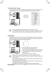
... orientation of the positive side (+) and the negative side (-) of purchase or local dealer if you are not able to keep the values (such as BIOS configurations, date, and time information) in the CMOS when the computer is replaced with local environmental regulations. Hardware Installation - 32 - Plug in accordance with an...
... orientation of the positive side (+) and the negative side (-) of purchase or local dealer if you are not able to keep the values (such as BIOS configurations, date, and time information) in the CMOS when the computer is replaced with local environmental regulations. Hardware Installation - 32 - Plug in accordance with an...

Manual
Page 33
...the latest version of BIOS from the Internet and updates the BIOS. To see more advanced BIOS Setup menu options, you not flash the BIOS. Inadequate BIOS flashing may result in the main menu of BIOS, it with caution. To upgrade the BIOS, use either the GIGABYTE Q-Flash or @BIOS utility. •... button in Chapter 1 for the beep codes description. • It is turned off, the battery on the motherboard. BIOS Setup Chapter 2 BIOS Setup BIOS (Basic Input and Output System) records hardware parameters of the system in the CMOS on the motherboard supplies the necessary power...
...the latest version of BIOS from the Internet and updates the BIOS. To see more advanced BIOS Setup menu options, you not flash the BIOS. Inadequate BIOS flashing may result in the main menu of BIOS, it with caution. To upgrade the BIOS, use either the GIGABYTE Q-Flash or @BIOS utility. •... button in Chapter 1 for the beep codes description. • It is turned off, the battery on the motherboard. BIOS Setup Chapter 2 BIOS Setup BIOS (Basic Input and Output System) records hardware parameters of the system in the CMOS on the motherboard supplies the necessary power...
Manual
Page 34
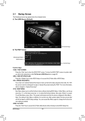
... boot order will directly boot from the device configured in BIOS Setup. : XPRESS RECOVERY2 If you to set the first boot device without having to accept. To show the BIOS POST screen. Motherboard Model BIOS Version X58A-OC F1f . . . . : BIOS Setup : XpressRecovery2 : Boot Menu : Qflash 03/07/...2011-X58-ICH10-7A89QG0TC-00 Function Keys Function Keys: : POST SCREEN Press the key to show the BIOS POST screen at system startup, ...
... boot order will directly boot from the device configured in BIOS Setup. : XPRESS RECOVERY2 If you to set the first boot device without having to accept. To show the BIOS POST screen. Motherboard Model BIOS Version X58A-OC F1f . . . . : BIOS Setup : XpressRecovery2 : Boot Menu : Qflash 03/07/...2011-X58-ICH10-7A89QG0TC-00 Function Keys Function Keys: : POST SCREEN Press the key to show the BIOS POST screen at system startup, ...
Manual
Page 35
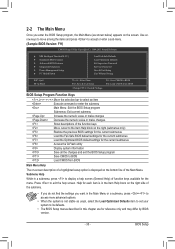
...for the current submenus Access the Q-Flash utility Display system information Save all the changes and exit the BIOS Setup program Save CMOS to BIOS Load CMOS from BIOS BIOS Setup Program Function Keys Move the selection bar to select an item Execute command or enter the submenu ...numeric value or make changes Decrease the numeric value or make changes Show descriptions of the function keys Move cursor to BIOS F12: Load CMOS from BIOS Main Menu Help The on-screen description of a highlighted setup option is not stable as shown below) appears on ...
...for the current submenus Access the Q-Flash utility Display system information Save all the changes and exit the BIOS Setup program Save CMOS to BIOS Load CMOS from BIOS BIOS Setup Program Function Keys Move the selection bar to select an item Execute command or enter the submenu ...numeric value or make changes Decrease the numeric value or make changes Show descriptions of the function keys Move cursor to BIOS F12: Load CMOS from BIOS Main Menu Help The on-screen description of a highlighted setup option is not stable as shown below) appears on ...

Manual
Page 36
... User Password Change, set , or disable password. It allows you can create up to load the BIOS settings from BIOS If your CPU, memory, etc. Standard CMOS Features Use this task.) BIOS Setup - 36 - First select the profile you wish to load, then press to complete. ...allows you to complete. F12: Load CMOS from a profile created before, without the hassles of reconfiguring the BIOS settings. Pressing to the confirmation message will exit BIOS Setup. (Pressing can also carry out this task.) Exit Without Saving Abandon all the changes made in the...
... User Password Change, set , or disable password. It allows you can create up to load the BIOS settings from BIOS If your CPU, memory, etc. Standard CMOS Features Use this task.) BIOS Setup - 36 - First select the profile you wish to load, then press to complete. ...allows you to complete. F12: Load CMOS from a profile created before, without the hassles of reconfiguring the BIOS settings. Pressing to the confirmation message will exit BIOS Setup. (Pressing can also carry out this task.) Exit Without Saving Abandon all the changes made in the...
Manual
Page 37
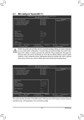
...Miscellaneous Settings [Press Enter] [Press Enter] [Press Enter] [Press Enter] [Press Enter] Item Help Menu Level BIOS Version BCLK CPU Frequency Memory Frequency Total Memory Size F1f 133.27 MHz 3198.64 MHz 1332.71 MHz 1024 MB CPU Temperature...(Inadequately altering the settings may result in system's failure to CPU, chipset, or memory and reduce the useful life of these components. BIOS Setup 2-3 MB Intelligent Tweaker(M.I.T.) CMOS Setup Utility-Copyright (C) 1984-2011 Award Software MB Intelligent Tweaker(M.I.T.) } M.I .T Current Status } ...
...Miscellaneous Settings [Press Enter] [Press Enter] [Press Enter] [Press Enter] [Press Enter] Item Help Menu Level BIOS Version BCLK CPU Frequency Memory Frequency Total Memory Size F1f 133.27 MHz 3198.64 MHz 1332.71 MHz 1024 MB CPU Temperature...(Inadequately altering the settings may result in system's failure to CPU, chipset, or memory and reduce the useful life of these components. BIOS Setup 2-3 MB Intelligent Tweaker(M.I.T.) CMOS Setup Utility-Copyright (C) 1984-2011 Award Software MB Intelligent Tweaker(M.I.T.) } M.I .T Current Status } ...


