Manual
Page 3
...from the Support\Motherboard\Technology Guide page on your motherboard revision before updating motherboard BIOS, drivers, or when looking for technical information. Documentation Classifications In order to assist in the use GIGABYTE's unique features, read the User's Manual. „ For instructions on how...the exclu- Copyright © 2007 GIGA-BYTE TECHNOLOGY CO., LTD. sive global distributor of this manual are legally registered to GIGABYTE UNITED INC. All rights reserved. The logo is the property of the motherboard is designated by copyright laws and is exclusively...
...from the Support\Motherboard\Technology Guide page on your motherboard revision before updating motherboard BIOS, drivers, or when looking for technical information. Documentation Classifications In order to assist in the use GIGABYTE's unique features, read the User's Manual. „ For instructions on how...the exclu- Copyright © 2007 GIGA-BYTE TECHNOLOGY CO., LTD. sive global distributor of this manual are legally registered to GIGABYTE UNITED INC. All rights reserved. The logo is the property of the motherboard is designated by copyright laws and is exclusively...
Manual
Page 4
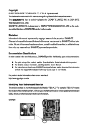
Table of Contents Box Contents ...6 OptionalItems ...6 GA-X48T-DQ6 Motherboard Layout 7 Block Diagram ...8 Chapter 1 Hardware Installation 9 1-1 Installation Precautions 9 1-2 Product Specifications 10 1-3 Installing the CPU and CPU Cooler 13 ... Card 19 1-6 Installing the SATA Bracket 20 1-7 Back Panel Connectors 21 1-8 Internal Connectors 23 Chapter 2 BIOS Setup 37 2-1 Startup Screen 38 2-2 The Main Menu 39 2-3 Standard CMOS Features 41 2-4 Advanced BIOS Features 43 2-5 IntegratedPeripherals 45 2-6 Power Management Setup 49 2-7 PnP/PCI Configurations 51 2-8 PC Health Status...
Table of Contents Box Contents ...6 OptionalItems ...6 GA-X48T-DQ6 Motherboard Layout 7 Block Diagram ...8 Chapter 1 Hardware Installation 9 1-1 Installation Precautions 9 1-2 Product Specifications 10 1-3 Installing the CPU and CPU Cooler 13 ... Card 19 1-6 Installing the SATA Bracket 20 1-7 Back Panel Connectors 21 1-8 Internal Connectors 23 Chapter 2 BIOS Setup 37 2-1 Startup Screen 38 2-2 The Main Menu 39 2-3 Standard CMOS Features 41 2-4 Advanced BIOS Features 43 2-5 IntegratedPeripherals 45 2-6 Power Management Setup 49 2-7 PnP/PCI Configurations 51 2-8 PC Health Status...
Manual
Page 5
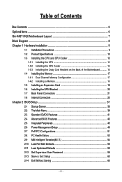
...63 3-5 Contact Us ...63 Chapter 4 Unique Features 65 4-1 Xpress Recovery2 65 4-2 BIOS Update Utilities 70 4-2-1 Updating the BIOS with the Q-Flash Utility 70 4-2-2 Updating the BIOS with the @BIOS Utility 73 4-3 EasyTune 5 Pro 75 4-4 Dynamic Energy Saver 76 4-5 Windows Vista ...ReadyBoost 78 Chapter 5 Appendix ...79 5-1 Configuring SATA Hard Drive(s 79 5-1-1 Configuring Intel® ICH9R SATA Controllers 79 5-1-2 Configuring GIGABYTE...
...63 3-5 Contact Us ...63 Chapter 4 Unique Features 65 4-1 Xpress Recovery2 65 4-2 BIOS Update Utilities 70 4-2-1 Updating the BIOS with the Q-Flash Utility 70 4-2-2 Updating the BIOS with the @BIOS Utility 73 4-3 EasyTune 5 Pro 75 4-4 Dynamic Energy Saver 76 4-5 Windows Vista ...ReadyBoost 78 Chapter 5 Appendix ...79 5-1 Configuring SATA Hard Drive(s 79 5-1-1 Configuring Intel® ICH9R SATA Controllers 79 5-1-2 Configuring GIGABYTE...

Manual
Page 8
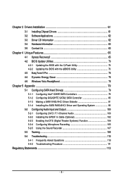
... PCIe CLK (100 MHz) RTL RTL 8111C 8111C x1 x1 x1 x1 x1 PCI Express Bus 2 SATA 3Gb/s ATA-133/100/66/ 33 IDE Channel GIGABYTE SATA2 PCI Bus TSB43AB23 3 IEEE 1394a Host Interface Intel® X48 DDR3 1900/1600/1333/ 1066/800 MHz Dual Channel Memory MCH CLK (400/333.../266/200 MHz) Intel® ICH9R Dual BIOS 6 SATA 3Gb/s 12 USB Ports LPC Bus CODEC IT8718 Floppy LPT Port COM Port PS/2 KB/Mouse TPM 2 PCI PCI CLK (33 MHz) Surround Speaker...
... PCIe CLK (100 MHz) RTL RTL 8111C 8111C x1 x1 x1 x1 x1 PCI Express Bus 2 SATA 3Gb/s ATA-133/100/66/ 33 IDE Channel GIGABYTE SATA2 PCI Bus TSB43AB23 3 IEEE 1394a Host Interface Intel® X48 DDR3 1900/1600/1333/ 1066/800 MHz Dual Channel Memory MCH CLK (400/333.../266/200 MHz) Intel® ICH9R Dual BIOS 6 SATA 3Gb/s 12 USB Ports LPC Bus CODEC IT8718 Floppy LPT Port COM Port PS/2 KB/Mouse TPM 2 PCI PCI CLK (33 MHz) Surround Speaker...
Manual
Page 12
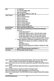
...motherboard model. (Note 5) The adjustable CPU voltage range depends on the CPU being used. (Note 6) Due to 0.35V with 1 MHz increment - GA-X48T-DQ6 Motherboard - 12 - Increase (G)MCH voltage by 0.025V to 0.775V with 1 MHz increment Š Support for Dynamic Energy Saver Š Norton Internet ...Security (OEM version) Š Voltage adjustments in BIOS Setup (CPU/DDR3/PCI-E) allow you install. (Note 4) Available functions in Easytune may differ by 0.05V to chipset limitation, Intel ICH9R ...
...motherboard model. (Note 5) The adjustable CPU voltage range depends on the CPU being used. (Note 6) Due to 0.35V with 1 MHz increment - GA-X48T-DQ6 Motherboard - 12 - Increase (G)MCH voltage by 0.025V to 0.775V with 1 MHz increment Š Support for Dynamic Energy Saver Š Norton Internet ...Security (OEM version) Š Voltage adjustments in BIOS Setup (CPU/DDR3/PCI-E) allow you install. (Note 4) Available functions in Easytune may differ by 0.05V to chipset limitation, Intel ICH9R ...

Manual
Page 17
... begin to install the memory: • Make sure that memory of the same capacity, brand, speed, and chips be used . (Go to GIGABYTE's website for optimum performance. • Each channel can be installed in Flex Memory Mode will double the original memory bandwidth. Dual Channel mode cannot ... MHz memory module. • When memory modules of different capacity and chips are installed, a message which says memory is installed, the BIOS will automatically detect the specifications and capacity of the same capacity, brand, speed, and chips be used and installed in the same colored ...
... begin to install the memory: • Make sure that memory of the same capacity, brand, speed, and chips be used . (Go to GIGABYTE's website for optimum performance. • Each channel can be installed in Flex Memory Mode will double the original memory bandwidth. Dual Channel mode cannot ... MHz memory module. • When memory modules of different capacity and chips are installed, a message which says memory is installed, the BIOS will automatically detect the specifications and capacity of the same capacity, brand, speed, and chips be used and installed in the same colored ...
Manual
Page 19
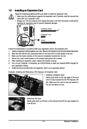
... the card straight out from the chassis back panel. 2. Make sure the card is fully inserted into the slot. 4. If necessary, go to BIOS Setup to make any required BIOS changes for your computer. Example: Installing and Removing a PCI Express x16 Graphics Card: • Installing a Graphics Card: Gently push down on the...
... the card straight out from the chassis back panel. 2. Make sure the card is fully inserted into the slot. 4. If necessary, go to BIOS Setup to make any required BIOS changes for your computer. Example: Installing and Removing a PCI Express x16 Graphics Card: • Installing a Graphics Card: Gently push down on the...
Manual
Page 28
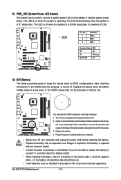
...face up). • Used batteries must be handled in S1 sleep state. The LED is on the chassis to keep the values (such as BIOS configurations, date, and time information) in the CMOS when the computer is in accordance with an equivalent one minute. (Or use a metal .... • Always turn off your computer and unplug the power cord before replacing the battery. • Replace the battery with local environmental regulations. GA-X48T-DQ6 Motherboard - 28 - Gently remove the battery from the battery holder and wait for 5 seconds.) 3. The LED keeps blinking when the system is turned...
...face up). • Used batteries must be handled in S1 sleep state. The LED is on the chassis to keep the values (such as BIOS configurations, date, and time information) in the CMOS when the computer is in accordance with an equivalent one minute. (Or use a metal .... • Always turn off your computer and unplug the power cord before replacing the battery. • Replace the battery with local environmental regulations. GA-X48T-DQ6 Motherboard - 28 - Gently remove the battery from the battery holder and wait for 5 seconds.) 3. The LED keeps blinking when the system is turned...
Manual
Page 29
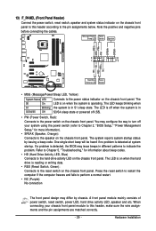
...chassis front panel. Note the positive and negative pins before connecting the cables. When connecting your system using the power switch (refer to Chapter 2, "BIOS Setup," "Power Management Setup," for information about beep codes. • HD (Hard Drive Activity LED, Blue) Connects to the hard drive activity... state or powered off (S5). • PW (Power Switch, Red): Connects to the power switch on when the system is detected, the BIOS may configure the way to turn off your chassis front panel module to this header according to perform a normal restart. • NC (Purple):...
...chassis front panel. Note the positive and negative pins before connecting the cables. When connecting your system using the power switch (refer to Chapter 2, "BIOS Setup," "Power Management Setup," for information about beep codes. • HD (Hard Drive Activity LED, Blue) Connects to the hard drive activity... state or powered off (S5). • PW (Power Switch, Red): Connects to the power switch on when the system is detected, the BIOS may configure the way to turn off your chassis front panel module to this header according to perform a normal restart. • NC (Purple):...
Manual
Page 34
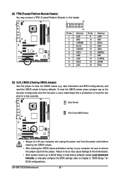
... temporarily short the two pins or use a metal object like a screwdriver to touch the two pins for BIOS configurations). date information and BIOS configurations) and reset the CMOS values to Chapter 2, "BIOS Setup," for a few seconds. GA-X48T-DQ6 Motherboard - 34 - 22) TPM (Trusted Platform Module Header) You may cause damage to the motherboard. • After...
... temporarily short the two pins or use a metal object like a screwdriver to touch the two pins for BIOS configurations). date information and BIOS configurations) and reset the CMOS values to Chapter 2, "BIOS Setup," for a few seconds. GA-X48T-DQ6 Motherboard - 34 - 22) TPM (Trusted Platform Module Header) You may cause damage to the motherboard. • After...
Manual
Page 37
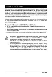
...risky, if you can press + in the main menu of the system in system's failure to activate certain system features. To upgrade the BIOS, use either the GIGABYTE Q-Flash or @BIOS utility. • Q-Flash allows the user to clear the CMOS values.) - 37 - If this occurs, try to clear the CMOS ...settings may result in the CMOS. Its major functions include conducting the Power-On Self-Test (POST) during the POST. To see more advanced BIOS Setup menu options, you do it is turned off, the battery on the motherboard supplies the necessary power to the CMOS to prevent system ...
...risky, if you can press + in the main menu of the system in system's failure to activate certain system features. To upgrade the BIOS, use either the GIGABYTE Q-Flash or @BIOS utility. • Q-Flash allows the user to clear the CMOS values.) - 37 - If this occurs, try to clear the CMOS ...settings may result in the CMOS. Its major functions include conducting the Power-On Self-Test (POST) during the POST. To see more advanced BIOS Setup menu options, you do it is turned off, the battery on the motherboard supplies the necessary power to the CMOS to prevent system ...
Manual
Page 38
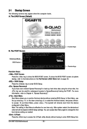
...-ICH9-6A89OG0FC-00 Function Keys Function Keys: : POST Screen Press the key to show the BIOS POST screen at system startup, refer to XpressRecovery2 during the POST. GA-X48T-DQ6 Motherboard - 38 - The POST Screen Motherboard Model BIOS Version Award Modular BIOS v6.00PG, An Energy Star Ally Copyright (C) 1984-2007, Award Software, Inc. Note: The...
...-ICH9-6A89OG0FC-00 Function Keys Function Keys: : POST Screen Press the key to show the BIOS POST screen at system startup, refer to XpressRecovery2 during the POST. GA-X48T-DQ6 Motherboard - 38 - The POST Screen Motherboard Model BIOS Version Award Modular BIOS v6.00PG, An Energy Star Ally Copyright (C) 1984-2007, Award Software, Inc. Note: The...
Manual
Page 39
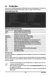
... & Exit Setup Exit Without Saving ESC: Quit F8: Q-Flash KLJI: Select Item F10: Save & Exit Setup F11: Save CMOS to BIOS F12: Load CMOS from BIOS Main Menu Help The onscreen description of a highlighted setup option is displayed on the bottom line of the submenu. • If you do... (as usual, select the Load Optimized Defaults item to set your system to its defaults. • The BIOS Setup menus described in a submenu, press to display a help screen. BIOS Setup Program Function Keys Move the selection bar to select an item Execute command or enter the submenu Main Menu...
... & Exit Setup Exit Without Saving ESC: Quit F8: Q-Flash KLJI: Select Item F10: Save & Exit Setup F11: Save CMOS to BIOS F12: Load CMOS from BIOS Main Menu Help The onscreen description of a highlighted setup option is displayed on the bottom line of the submenu. • If you do... (as usual, select the Load Optimized Defaults item to set your system to its defaults. • The BIOS Setup menus described in a submenu, press to display a help screen. BIOS Setup Program Function Keys Move the selection bar to select an item Execute command or enter the submenu Main Menu...
Manual
Page 40
...„ MB Intelligent Tweaker(M.I.T.) Use this task.) GA-X48T-DQ6 Motherboard - 40 - First select the profile you can also carry out this function to load the BIOS settings from a profile created before, without the hassles of reconfiguring the BIOS settings. It allows you to restrict access to ...-performance system operations. „ Set Supervisor Password Change, set , or disable password. A supervisor password allows you to save the current BIOS settings to 8 profiles (Profile 1-8) and name each profile. You can also carry out this menu to configure the clock, frequency and...
...„ MB Intelligent Tweaker(M.I.T.) Use this task.) GA-X48T-DQ6 Motherboard - 40 - First select the profile you can also carry out this function to load the BIOS settings from a profile created before, without the hassles of reconfiguring the BIOS settings. It allows you to restrict access to ...-performance system operations. „ Set Supervisor Password Change, set , or disable password. A supervisor password allows you to save the current BIOS settings to 8 profiles (Profile 1-8) and name each profile. You can also carry out this menu to configure the clock, frequency and...
Manual
Page 41
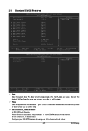
...:0:0. Select the desired field and use the up arrow or down arrow key to set the time. is week (read-only), month, date and year. BIOS Setup Select the desired field and use the up arrow or down arrow key to set the date.
...:0:0. Select the desired field and use the up arrow or down arrow key to set the time. is week (read-only), month, date and year. BIOS Setup Select the desired field and use the up arrow or down arrow key to set the date.
Manual
Page 42
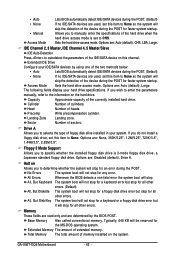
.... All, But Disk/Key The system boot will not stop for a keyboard or a floppy disk drive error but it will stop for all other errors. GA-X48T-DQ6 Motherboard - 42 - IDE Channel 2, 3 Master, IDE Channel 4, 5 Master/Slave IDE Auto-Detection Press to autodetect the parameters of the device during the ... determined by using one of the device during the POST for faster system startup. • Auto • None • Manual Access Mode Lets BIOS automatically detect IDE/SATA devices during the POST. (Default) If no IDE/SATA devices are used , set this item to None so the system ...
.... All, But Disk/Key The system boot will not stop for a keyboard or a floppy disk drive error but it will stop for all other errors. GA-X48T-DQ6 Motherboard - 42 - IDE Channel 2, 3 Master, IDE Channel 4, 5 Master/Slave IDE Auto-Detection Press to autodetect the parameters of the device during the ... determined by using one of the device during the POST for faster system startup. • Auto • None • Manual Access Mode Lets BIOS automatically detect IDE/SATA devices during the POST. (Default) If no IDE/SATA devices are used , set this item to None so the system ...

Manual
Page 43
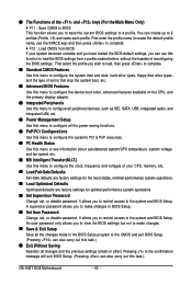
...list. Password Check Specifies whether a password is required for booting the system and for entering the BIOS Setup program. 2-4 Advanced BIOS Features CMOS Setup Utility-Copyright (C) 1984-2007 Award Software Advanced BIOS Features ` Hard Disk Boot Priority First Boot Device [Press Enter] [Floppy] Item Help Menu ...unique features, please visit Intel's website. - 43 - to exit this item, set the password(s) under the Set Supervisor/User Password item in the BIOS Main Menu. Options are: Floppy, LS120, Hard Disk, CDROM, ZIP, USB-FDD, USB-ZIP, USB-CDROM, USB-HDD, Legacy LAN, Disabled...
...list. Password Check Specifies whether a password is required for booting the system and for entering the BIOS Setup program. 2-4 Advanced BIOS Features CMOS Setup Utility-Copyright (C) 1984-2007 Award Software Advanced BIOS Features ` Hard Disk Boot Priority First Boot Device [Press Enter] [Floppy] Item Help Menu ...unique features, please visit Intel's website. - 43 - to exit this item, set the password(s) under the Set Supervisor/User Password item in the BIOS Main Menu. Options are: Floppy, LS120, Hard Disk, CDROM, ZIP, USB-FDD, USB-ZIP, USB-CDROM, USB-HDD, Legacy LAN, Disabled...
Manual
Page 45
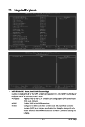
... storage driver to AHCI mode. AHCI Configures the SATA controllers to enable advanced Serial ATA features such as Native Command Queuing and hot plug. - 45 - BIOS Setup 2-5 Integrated Peripherals CMOS Setup Utility-Copyright (C) 1984-2007 Award Software Integrated Peripherals SATA RAID/AHCI Mode SATA Port0-3 Native Mode USB Controller USB 2.0 Controller...
... storage driver to AHCI mode. AHCI Configures the SATA controllers to enable advanced Serial ATA features such as Native Command Queuing and hot plug. - 45 - BIOS Setup 2-5 Integrated Peripherals CMOS Setup Utility-Copyright (C) 1984-2007 Award Software Integrated Peripherals SATA RAID/AHCI Mode SATA Port0-3 Native Mode USB Controller USB 2.0 Controller...
Manual
Page 47
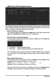
... diagnosing your LAN cable: When No LAN Cable Is Attached... Note: Part 4-5 and Part 7-8 are not used in MS-DOS mode; When a Cable Problem Occurs... BIOS Setup If no cable problem is attached to the fault or short. Part1-2 Status = Open Part3-6 Status = Open Part4-5 Status = Open Part7-8 Status = Open / Length...
... diagnosing your LAN cable: When No LAN Cable Is Attached... Note: Part 4-5 and Part 7-8 are not used in MS-DOS mode; When a Cable Problem Occurs... BIOS Setup If no cable problem is attached to the fault or short. Part1-2 Status = Open Part3-6 Status = Open Part4-5 Status = Open Part7-8 Status = Open / Length...

Manual
Page 49
... the power button is pressed for 4 seconds to turn off . Note: To use this function, you need an ATX power supply providing at any time. BIOS Setup PME Event Wake Up Allows the system to be resumed at least 1A on Suspend) sleep state. Enables the system to enter the ACPI...
... the power button is pressed for 4 seconds to turn off . Note: To use this function, you need an ATX power supply providing at any time. BIOS Setup PME Event Wake Up Allows the system to be resumed at least 1A on Suspend) sleep state. Enables the system to enter the ACPI...


