
Manual
Page 4
...GA-VM900M Motherboard Layout 7 Block Diagram ...8 Chapter 1 Hardware Installation 9 1-1 Considerations Prior to Installation 9 1-2 Feature Summary 10 1-3 Installation of the CPU and CPU Cooler 12 1-3-1 Installation of the CPU 12 1-3-2 Installation of the CPU Cooler 13 1-4 Installation of Memory 14 1-5 Installation of Expansion Cards 15 1-6 I/O Back Panel Introduction 16 1-7 Connectors Introduction 17 Chapter 2 BIOS... Setup 27 The Main Menu (For example: BIOS Ver. : FAm 28 2-1 Standard CMOS Features 30 2-2 Advanced BIOS Features 32 2-3 ...
...GA-VM900M Motherboard Layout 7 Block Diagram ...8 Chapter 1 Hardware Installation 9 1-1 Considerations Prior to Installation 9 1-2 Feature Summary 10 1-3 Installation of the CPU and CPU Cooler 12 1-3-1 Installation of the CPU 12 1-3-2 Installation of the CPU Cooler 13 1-4 Installation of Memory 14 1-5 Installation of Expansion Cards 15 1-6 I/O Back Panel Introduction 16 1-7 Connectors Introduction 17 Chapter 2 BIOS... Setup 27 The Main Menu (For example: BIOS Ver. : FAm 28 2-1 Standard CMOS Features 30 2-2 Advanced BIOS Features 32 2-3 ...
Manual
Page 5
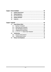
Chapter 3 Drivers Installation 45 3-1 Installing Chipset Drivers 45 3-2 SoftwareApplications 46 3-3 Driver CD Information 46 3-4 Hardware Information 47 3-5 Contact Us ...47 Chapter 4 Appendix ...49 4-1 Unique Software Utilities 49 4-1-1 EasyTune 5 Introduction 49 4-1-2 Xpress Recovery2 Introduction 50 4-1-3 Flash BIOS Method Introduction 52 4-1-4 Configuring SATA Hard Drive(s 56 4-1-5 2- / 4- / 5.1- / 7.1- Channel Audio Introduction 67 4-2 Troubleshooting 72 4-2-1 Frequently Asked Questions 72 4-2-2 Troubleshooting Procedure 73 4-3 Windows Vista ReadyBoost 75 - 5 -
Chapter 3 Drivers Installation 45 3-1 Installing Chipset Drivers 45 3-2 SoftwareApplications 46 3-3 Driver CD Information 46 3-4 Hardware Information 47 3-5 Contact Us ...47 Chapter 4 Appendix ...49 4-1 Unique Software Utilities 49 4-1-1 EasyTune 5 Introduction 49 4-1-2 Xpress Recovery2 Introduction 50 4-1-3 Flash BIOS Method Introduction 52 4-1-4 Configuring SATA Hard Drive(s 56 4-1-5 2- / 4- / 5.1- / 7.1- Channel Audio Introduction 67 4-2 Troubleshooting 72 4-2-1 Frequently Asked Questions 72 4-2-2 Troubleshooting Procedure 73 4-3 Windows Vista ReadyBoost 75 - 5 -
Manual
Page 8
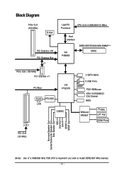
... Express x1 PCI Bus VIA VT8237S RJ45 LAN RTL8201 CODEC 2 PCI 2 SATA 3Gb/s 8 USB Ports PS/2 KB/Mouse ATA-133/100/66/33 IDE Channel BIOS Winbond W83627 Floppy LPT Port COM Ports PCI CLK (33 MHz) Surround Speaker Out Center/Subwoofer Speaker Out Side Speaker Out MIC Line-Out Line...
... Express x1 PCI Bus VIA VT8237S RJ45 LAN RTL8201 CODEC 2 PCI 2 SATA 3Gb/s 8 USB Ports PS/2 KB/Mouse ATA-133/100/66/33 IDE Channel BIOS Winbond W83627 Floppy LPT Port COM Ports PCI CLK (33 MHz) Surround Speaker Out Center/Subwoofer Speaker Out Side Speaker Out MIC Line-Out Line...

Manual
Page 11
... fan failure warning Š CPU smart fan control (Note 4) BIOS Š 1 4 Mbit flash ROM Š Use of licensed AWARD BIOS Š PnP 1.0a, DMI 2.0, SM BIOS 2.3, ACPI 1.0b Additional Features Š Supports @BIOS Š Supports Download Center Š Supports Q-Flash Š ...Supports EasyTune (only supports Hardware Monitor function) (Note 5) Š Supports Xpress Install Š Supports Xpress Recovery2 Š Supports Xpress BIOS Rescue Bundle Software Š Norton Internet Security (OEM version) Form Factor Š Micro ATX form factor; 24.4cm x 23.3cm (Note ...
... fan failure warning Š CPU smart fan control (Note 4) BIOS Š 1 4 Mbit flash ROM Š Use of licensed AWARD BIOS Š PnP 1.0a, DMI 2.0, SM BIOS 2.3, ACPI 1.0b Additional Features Š Supports @BIOS Š Supports Download Center Š Supports Q-Flash Š ...Supports EasyTune (only supports Hardware Monitor function) (Note 5) Š Supports Xpress Install Š Supports Xpress Recovery2 Š Supports Xpress BIOS Rescue Bundle Software Š Norton Internet Security (OEM version) Form Factor Š Micro ATX form factor; 24.4cm x 23.3cm (Note ...
Manual
Page 12
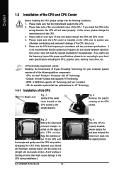
...174; Chipset that the system bus frequency be set beyond the proper specifications, please do so according to the CPU during installation.) GA-VM900M Motherboard - 12 - English 1-3 Installation of the CPU may occur. 5. Align the indented corner of the following conditions: 1. ...Enabling the functionality of Hyper-Threading Technology for your hardware specifications including the CPU, graphics card, memory, hard drive, etc. BIOS: A BIOS that the motherboard supports the CPU. 2. If you install the CPU in a straight and downwards motion. Please set the ...
...174; Chipset that the system bus frequency be set beyond the proper specifications, please do so according to the CPU during installation.) GA-VM900M Motherboard - 12 - English 1-3 Installation of the CPU may occur. 5. Align the indented corner of the following conditions: 1. ...Enabling the functionality of Hyper-Threading Technology for your hardware specifications including the CPU, graphics card, memory, hard drive, etc. BIOS: A BIOS that the motherboard supports the CPU. 2. If you install the CPU in a straight and downwards motion. Please set the ...

Manual
Page 14
Notch DDR2 DIMM Fig.1 The DIMM socket has a notch, so the DIMM memory module can be inserted only in one direction. GA-VM900M Motherboard - 14 - The motherboard supports DDR2 memory modules, whereby BIOS will automatically detect memory capacity and specifications. Memory modules are unable to lock the DIMM module. It is recommended that they...
Notch DDR2 DIMM Fig.1 The DIMM socket has a notch, so the DIMM memory module can be inserted only in one direction. GA-VM900M Motherboard - 14 - The motherboard supports DDR2 memory modules, whereby BIOS will automatically detect memory capacity and specifications. Memory modules are unable to lock the DIMM module. It is recommended that they...

Manual
Page 15
...the Card: Press the white latch at the end of Expansion Cards Follow the steps below to correctly install your computer. If necessary, go to BIOS Setup to the chassis back panel with a screw. 5. Remove the metal slot cover from the slot. - 15 - Secure the card's ...metal bracket to make any required BIOS changes for your card. Example: Installing and Removing a PCI Express x16 Graphics Card: • Installing a Graphics Card: Gently insert the graphics card into...
...the Card: Press the white latch at the end of Expansion Cards Follow the steps below to correctly install your computer. If necessary, go to BIOS Setup to the chassis back panel with a screw. 5. Remove the metal slot cover from the slot. - 15 - Secure the card's ...metal bracket to make any required BIOS changes for your card. Example: Installing and Removing a PCI Express x16 Graphics Card: • Installing a Graphics Card: Gently insert the graphics card into...

Manual
Page 26
... off the computer and unplug the power cord. 2. date information and BIOS configurations) and reset the CMOS values to erase CMOS... 1. To clear the CMOS values, place a jumper cap on the computer. - 26 - Open: Normal Short: Clear CMOS 18) BATTERY GA-VM900M Motherboard Danger of used batteries according to touch the two pins...
... off the computer and unplug the power cord. 2. date information and BIOS configurations) and reset the CMOS values to erase CMOS... 1. To clear the CMOS values, place a jumper cap on the computer. - 26 - Open: Normal Short: Clear CMOS 18) BATTERY GA-VM900M Motherboard Danger of used batteries according to touch the two pins...
Manual
Page 27
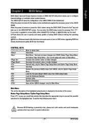
... features. Q-Flash allows the user to quickly and easily update or backup BIOS without entering the operating system. @BIOS is turned off, the battery on the motherboard supplies the necessary power to a new BIOS, either GIGABYTE's Q-Flash or @BIOS utility can enter the BIOS setup screen by pressing "Ctrl + F1". To exit the Help Window press...
... features. Q-Flash allows the user to quickly and easily update or backup BIOS without entering the operating system. @BIOS is turned off, the battery on the motherboard supplies the necessary power to a new BIOS, either GIGABYTE's Q-Flash or @BIOS utility can enter the BIOS setup screen by pressing "Ctrl + F1". To exit the Help Window press...

Manual
Page 28
... to select among the items and press to exit this chapter are for reference only and may differ from the exact settings for your motherboard. GA-VM900M Motherboard - 28 - English : Boot Menu Select boot sequence for stability. 3. Award Modular BIOS v6.00PG, An Energy Star Ally Copyright (C) 1984-2007, Award Software, Inc.
... to select among the items and press to exit this chapter are for reference only and may differ from the exact settings for your motherboard. GA-VM900M Motherboard - 28 - English : Boot Menu Select boot sequence for stability. 3. Award Modular BIOS v6.00PG, An Energy Star Ally Copyright (C) 1984-2007, Award Software, Inc.

Manual
Page 29
... „ Standard CMOS Features This setup page includes all the items in standard compatible BIOS. „ Advanced BIOS Features This setup page includes all the items of Award special enhanced features. „ Integrated Peripherals This setup page includes all onboard peripherals. „ Power ...
... „ Standard CMOS Features This setup page includes all the items in standard compatible BIOS. „ Advanced BIOS Features This setup page includes all the items of Award special enhanced features. „ Integrated Peripherals This setup page includes all onboard peripherals. „ Power ...

Manual
Page 30
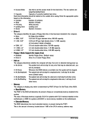
Week Month The week, from Sun to 31 (or the maximum allowed in the month) Year The year, from 1 to Sat, determined by the BIOS and is , , , . The month, Jan. time clock. For example, 1 p.m. IDE Channel 0/1 Master/Slave IDE devices setup. Day The day, from 2000 through 2099...None Select this if no IDE/SATA devices are used and the system will skip the automatic detection step and allow for the hard drive. GA-VM900M Motherboard - 30 - You can use one of currectly installed hard drive. Extended IDE Drive You can use one of three methods: • Auto...
Week Month The week, from Sun to 31 (or the maximum allowed in the month) Year The year, from 1 to Sat, determined by the BIOS and is , , , . The month, Jan. time clock. For example, 1 p.m. IDE Channel 0/1 Master/Slave IDE devices setup. Day The day, from 2000 through 2099...None Select this if no IDE/SATA devices are used and the system will skip the automatic detection step and allow for the hard drive. GA-VM900M Motherboard - 30 - You can use one of currectly installed hard drive. Extended IDE Drive You can use one of three methods: • Auto...
Manual
Page 31
... Zone Landing zone Sector Number of sectors Drive A The category identifies the types of base (or conventional) memory installed in the system. Whenever the BIOS detects a non-fatal error the system will be prompted. All, But Keyboard The system boot will not stop for a keyboard or disk error;... The value of the BIOS. BIOS Setup Enter the appropriate option based on the outside drive casing. All, But Disk/Key The system boot will not stop for systems with 512...
... Zone Landing zone Sector Number of sectors Drive A The category identifies the types of base (or conventional) memory installed in the system. Whenever the BIOS detects a non-fatal error the system will be prompted. All, But Keyboard The system boot will not stop for a keyboard or disk error;... The value of the BIOS. BIOS Setup Enter the appropriate option based on the outside drive casing. All, But Disk/Key The system boot will not stop for systems with 512...

Manual
Page 32
...(or add-on cards) SCSI, RAID, etc. First / Second / Third Boot Device Floppy LS120 Select your boot device priority by Floppy. GA-VM900M Motherboard - 32 - Dual display function This feature allows user to move it down the list. The onboard graphics will show up . 64M...of the monitor display from either the onboard graphics or the external graphics card. English 2-2 Advanced BIOS Features CMOS Setup Utility-Copyright (C) 1984-2007 Award Software Advanced BIOS Features Init Display First Dual display function VGA Share Memory Size ` Hard Disk Boot Priority First Boot...
...(or add-on cards) SCSI, RAID, etc. First / Second / Third Boot Device Floppy LS120 Select your boot device priority by Floppy. GA-VM900M Motherboard - 32 - Dual display function This feature allows user to move it down the list. The onboard graphics will show up . 64M...of the monitor display from either the onboard graphics or the external graphics card. English 2-2 Advanced BIOS Features CMOS Setup Utility-Copyright (C) 1984-2007 Award Software Advanced BIOS Features Init Display First Dual display function VGA Share Memory Size ` Hard Disk Boot Priority First Boot...

Manual
Page 33
... by LAN. capability. Disabled (Default value) Disable CPU Hyper Threading. CPU EIST Function (Note) Enabled Disabled Enable CPU EIST function. (Default value) Disable EIST function. BIOS Setup HDD S.M.A.R.T. Disable HDD S.M.A.R.T. Limit CPUID Max. CPU Thermal Monitor 2 (TM2) (Note) Enabled Disabled Enable CPU Thermal Monitor 2 (TM2) function. (Default value) Disable CPU Thermal...
... by LAN. capability. Disabled (Default value) Disable CPU Hyper Threading. CPU EIST Function (Note) Enabled Disabled Enable CPU EIST function. (Default value) Disable EIST function. BIOS Setup HDD S.M.A.R.T. Disable HDD S.M.A.R.T. Limit CPUID Max. CPU Thermal Monitor 2 (TM2) (Note) Enabled Disabled Enable CPU Thermal Monitor 2 (TM2) function. (Default value) Disable CPU Thermal...

Manual
Page 35
...1 and address is 2F8/IRQ3. 3E8/IRQ4 2E8/IRQ3 Enable onboard Serial port 1 and address is 2E8/IRQ3. Disable this function. BIOS Setup USB 2.0 Controller Enabled Enable the USB 2.0 controller. (Default value) Disabled Disable this function. English USB 1.1 Controller Enabled Enable the.... (Default value) Disabled Disable this function. Onboard Parallel Port Disabled 378/IRQ7 Disable onboard LPT port. Onboard Serial Port 1 Auto BIOS will automatically setup the port 2 address. 3F8/IRQ4 2F8/IRQ3 Enable onboard Serial port 2 and address is 3BC/IRQ7. - 35...
...1 and address is 2F8/IRQ3. 3E8/IRQ4 2E8/IRQ3 Enable onboard Serial port 1 and address is 2E8/IRQ3. Disable this function. BIOS Setup USB 2.0 Controller Enabled Enable the USB 2.0 controller. (Default value) Disabled Disable this function. English USB 1.1 Controller Enabled Enable the.... (Default value) Disabled Disable this function. Onboard Parallel Port Disabled 378/IRQ7 Disable onboard LPT port. Onboard Serial Port 1 Auto BIOS will automatically setup the port 2 address. 3F8/IRQ4 2F8/IRQ3 Enable onboard Serial port 2 and address is 3BC/IRQ7. - 35...
Manual
Page 37
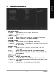
... button 4 seconds to power off . PS2KB Power On Select Disabled Disable this function. (Default value) Password Enter from S3. (Default value) Disabled Disable this function. BIOS Setup Keyboard 98 If your keyboard to the Last state before AC-power off . Enter suspend if button is pressed less than 4 seconds. Memory When...
... button 4 seconds to power off . PS2KB Power On Select Disabled Disable this function. (Default value) Password Enter from S3. (Default value) Disabled Disable this function. BIOS Setup Keyboard 98 If your keyboard to the Last state before AC-power off . Enter suspend if button is pressed less than 4 seconds. Memory When...
Manual
Page 39
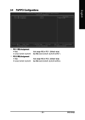
... ESC: Exit F1: General Help F7: Optimized Defaults Auto assign IRQ to PCI 1. (Default value) Set IRQ 3,4,5,7,9,10,11,12,14,15 to PCI 2. - 39 - BIOS Setup
... ESC: Exit F1: General Help F7: Optimized Defaults Auto assign IRQ to PCI 1. (Default value) Set IRQ 3,4,5,7,9,10,11,12,14,15 to PCI 2. - 39 - BIOS Setup

Manual
Page 41
Enabled When this function. English CPU Smart FAN Control Disabled Disable this function is enabled, CPU fan will run at different speed depending on their requirements. (Default value) - 41 - Users can adjust the fan speed with EasyTune based on CPU temperature. BIOS Setup
Enabled When this function. English CPU Smart FAN Control Disabled Disable this function is enabled, CPU fan will run at different speed depending on their requirements. (Default value) - 41 - Users can adjust the fan speed with EasyTune based on CPU temperature. BIOS Setup
Manual
Page 42
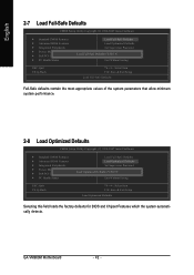
...of the system parameters that allow minimum system performance. 2-8 Load Optimized Defaults CMOS Setup Utility-Copyright (C) 1984-2007 Award Software ` Standard CMOS Features ` Advanced BIOS Features ` Integrated Peripherals ` Power Management Setup ` PnP/PCI Configurations ` PC Health Status ESC: Quit F8: Q-Flash Load Fail-Safe Defaults Load Optimized ... Exit Without Saving KLJI: Select Item F10: Save & Exit Setup Load Optimized Defaults Selecting this field loads the factory defaults for BIOS and Chipset Features which the system automatically detects. GA-VM900M Motherboard - 42 -
...of the system parameters that allow minimum system performance. 2-8 Load Optimized Defaults CMOS Setup Utility-Copyright (C) 1984-2007 Award Software ` Standard CMOS Features ` Advanced BIOS Features ` Integrated Peripherals ` Power Management Setup ` PnP/PCI Configurations ` PC Health Status ESC: Quit F8: Q-Flash Load Fail-Safe Defaults Load Optimized ... Exit Without Saving KLJI: Select Item F10: Save & Exit Setup Load Optimized Defaults Selecting this field loads the factory defaults for BIOS and Chipset Features which the system automatically detects. GA-VM900M Motherboard - 42 -


