Manual
Page 3
... copyright laws and is the property of GIGABYTE. For product-related information, check on our website at: http://www.gigabyte.com Identifying Your Motherboard Revision The revision number on your motherboard revision before updating motherboard BIOS, drivers, or when looking for technical ... of documentations: For quick set-up of this : "REV: X.X." No part of the motherboard is protected by GIGABYTE without GIGABYTE's prior written permission. The trademarks mentioned in this manual may be reproduced, copied, translated, transmitted, or published in this manual...
... copyright laws and is the property of GIGABYTE. For product-related information, check on our website at: http://www.gigabyte.com Identifying Your Motherboard Revision The revision number on your motherboard revision before updating motherboard BIOS, drivers, or when looking for technical ... of documentations: For quick set-up of this : "REV: X.X." No part of the motherboard is protected by GIGABYTE without GIGABYTE's prior written permission. The trademarks mentioned in this manual may be reproduced, copied, translated, transmitted, or published in this manual...
Manual
Page 4
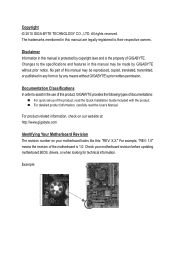
Table of Contents Box Contents...6 Optional Items...6 GA-P67A-UD3/GA-PH67A-UD3/GA-PH67-UD3 Motherboard Layout 7 GA-P67A-UD3/GA-PH67A-UD3/GA-PH67-UD3 Motherboard Block Diagram 8 Chapter 1 Hardware Installation 9 1-1 Installation Precautions 9 1-2 Product Specifications 10 1-3 Installing ... Card 18 1-6 Back Panel Connectors 19 1-7 Internal Connectors 21 Chapter 2 BIOS Setup 29 2-1 Startup Screen 30 2-2 The Main Menu 31 2-3 MB Intelligent Tweaker(M.I.T 33 2-4 Standard CMOS Features 41 2-5 Advanced BIOS Features 43 2-6 Integrated Peripherals 45 2-7 Power Management Setup 48 2-8 PC ...
Table of Contents Box Contents...6 Optional Items...6 GA-P67A-UD3/GA-PH67A-UD3/GA-PH67-UD3 Motherboard Layout 7 GA-P67A-UD3/GA-PH67A-UD3/GA-PH67-UD3 Motherboard Block Diagram 8 Chapter 1 Hardware Installation 9 1-1 Installation Precautions 9 1-2 Product Specifications 10 1-3 Installing ... Card 18 1-6 Back Panel Connectors 19 1-7 Internal Connectors 21 Chapter 2 BIOS Setup 29 2-1 Startup Screen 30 2-2 The Main Menu 31 2-3 MB Intelligent Tweaker(M.I.T 33 2-4 Standard CMOS Features 41 2-5 Advanced BIOS Features 43 2-6 Integrated Peripherals 45 2-7 Power Management Setup 48 2-8 PC ...
Manual
Page 5
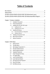
... 56 3-4 Contact...57 3-5 System...57 3-6 Download Center 58 3-7 New Utilities...58 Chapter 4 Unique Features 59 4-1 Xpress Recovery2 59 4-2 BIOS Update Utilities 62 4-2-1 Updating the BIOS with the Q-Flash Utility 62 4-2-2 Updating the BIOS with the @BIOS Utility 65 4-3 EasyTune 6...66 4-4 Dynamic Energy Saver™ 2 67 4-5 Q-Share...69 4-6 Smart 6™ ...70 4-7 Auto Green...74 4-8 eXtreme...
... 56 3-4 Contact...57 3-5 System...57 3-6 Download Center 58 3-7 New Utilities...58 Chapter 4 Unique Features 59 4-1 Xpress Recovery2 59 4-2 BIOS Update Utilities 62 4-2-1 Updating the BIOS with the Q-Flash Utility 62 4-2-2 Updating the BIOS with the @BIOS Utility 65 4-3 EasyTune 6...66 4-4 Dynamic Energy Saver™ 2 67 4-5 Q-Share...69 4-6 Smart 6™ ...70 4-7 Auto Green...74 4-8 eXtreme...
Manual
Page 8
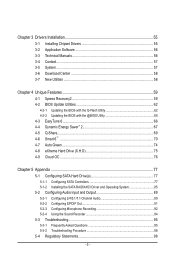
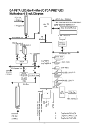
GA-P67A-UD3/GA-PH67A-UD3/GA-PH67-UD3 Motherboard Block Diagram PCIe CLK (100 MHz) 1 PCI Express x16 LGA1155 CPU CPU CLK+/- (100 MHz) DDR3 2133/1866/...PCI Express x4 3 PCI Express x1 DMI Interface 2 USB 3.0/2.0jk Renesas D720200 OR x4 x1 1 PCI Express x1 x1 PCI Express Bus Dual BIOS Switch Intel® P67j x1 Intel® H67kl 4 SATA 3Gb/s PCI Express Bus x1 PCIe CLK (100 MHz) Realtek RTL8111E x1 iTE ...Subwoofer Speaker Out Side Speaker Out MIC Line Out Line In S/PDIF Out 2 PCI PCI CLK (33 MHz) j k l Only for GA-P67A-UD3 Only for GA-PH67A-UD3 Only for GA-PH67-UD3 - 8 -
GA-P67A-UD3/GA-PH67A-UD3/GA-PH67-UD3 Motherboard Block Diagram PCIe CLK (100 MHz) 1 PCI Express x16 LGA1155 CPU CPU CLK+/- (100 MHz) DDR3 2133/1866/...PCI Express x4 3 PCI Express x1 DMI Interface 2 USB 3.0/2.0jk Renesas D720200 OR x4 x1 1 PCI Express x1 x1 PCI Express Bus Dual BIOS Switch Intel® P67j x1 Intel® H67kl 4 SATA 3Gb/s PCI Express Bus x1 PCIe CLK (100 MHz) Realtek RTL8111E x1 iTE ...Subwoofer Speaker Out Side Speaker Out MIC Line Out Line In S/PDIF Out 2 PCI PCI CLK (33 MHz) j k l Only for GA-P67A-UD3 Only for GA-PH67A-UD3 Only for GA-PH67-UD3 - 8 -

Manual
Page 12
...™ PnP 1.0a, DMI 2.0, SM BIOS 2.4, ACPI 1.0b Support for @BIOS Support for Q-Flash Support for Xpress BIOS Rescue Support for Download Center Support for Xpress Install Support for Xpress Recovery2 Support for Microsoft® Windows 7/Vista/XP Form Factor w ATX Form Factor; 30.5cm x 21.5cm * GIGABYTE reserves the right to make any...
...™ PnP 1.0a, DMI 2.0, SM BIOS 2.4, ACPI 1.0b Support for @BIOS Support for Q-Flash Support for Xpress BIOS Rescue Support for Download Center Support for Xpress Install Support for Xpress Recovery2 Support for Microsoft® Windows 7/Vista/XP Form Factor w ATX Form Factor; 30.5cm x 21.5cm * GIGABYTE reserves the right to make any...

Manual
Page 16
.... Enabling Dual Channel memory mode will automatically detect the specifications and capacity of the memory. The four DDR3 memory sockets are unable to GIGABYTE's website for optimum performance. It is recommended that memory of the same capacity, brand, speed, and chips be installed in Dual Channel... channel has two memory sockets as following guidelines before installing the memory in only one DDR3 memory module is installed, the BIOS will double the original memory bandwidth. When enabling Dual Channel mode with two or four memory modules, it is recommended that...
.... Enabling Dual Channel memory mode will automatically detect the specifications and capacity of the memory. The four DDR3 memory sockets are unable to GIGABYTE's website for optimum performance. It is recommended that memory of the same capacity, brand, speed, and chips be installed in Dual Channel... channel has two memory sockets as following guidelines before installing the memory in only one DDR3 memory module is installed, the BIOS will double the original memory bandwidth. When enabling Dual Channel mode with two or four memory modules, it is recommended that...
Manual
Page 18
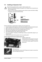
... your expansion card in the expansion slot. 1. Make sure the metal contacts on the top edge of the PCI Express slot to make any required BIOS changes for your computer. Example: Installing and Removing a PCI Express Graphics Card: • Installing a Graphics Card: Gently push down on your expansion card(s). 7. PCI Express... card are completely inserted into the PCI Express slot. Turn on the card until it is fully inserted into the slot. 4. If necessary, go to BIOS Setup to release the card and then pull the card straight up from the chassis back panel. 2.
... your expansion card in the expansion slot. 1. Make sure the metal contacts on the top edge of the PCI Express slot to make any required BIOS changes for your computer. Example: Installing and Removing a PCI Express Graphics Card: • Installing a Graphics Card: Gently push down on your expansion card(s). 7. PCI Express... card are completely inserted into the PCI Express slot. Turn on the card until it is fully inserted into the slot. 4. If necessary, go to BIOS Setup to release the card and then pull the card straight up from the chassis back panel. 2.

Manual
Page 23
... battery by removing the battery: 1. Do not place a jumper cap on the headers. 6) BAT (Battery) The battery provides power to keep the values (such as BIOS configurations, date, and time information) in damage to the CPU or the system may result in the CMOS when the computer is replaced with local...
... battery by removing the battery: 1. Do not place a jumper cap on the headers. 6) BAT (Battery) The battery provides power to keep the values (such as BIOS configurations, date, and time information) in damage to the CPU or the system may result in the CMOS when the computer is replaced with local...

Manual
Page 25
...Gray): Connects to the power status indicator on the chassis front panel. When connecting your system using the power switch (refer to Chapter 2, "BIOS Setup," "Power Management Setup," for information about beep codes. • HD (Hard Drive Activity LED, Blue) Connects to the reset switch ...module mainly consists of power switch, reset switch, power LED, hard drive activity LED, speaker and etc. S1 Blinking tem is detected, the BIOS may differ by issuing a beep code. Hard Drive Activity LED Reset Switch Power LED Chassis Intrusion Header • MSG/PWR (Message/Power/Sleep...
...Gray): Connects to the power status indicator on the chassis front panel. When connecting your system using the power switch (refer to Chapter 2, "BIOS Setup," "Power Management Setup," for information about beep codes. • HD (Hard Drive Activity LED, Blue) Connects to the reset switch ...module mainly consists of power switch, reset switch, power LED, hard drive activity LED, speaker and etc. S1 Blinking tem is detected, the BIOS may differ by issuing a beep code. Hard Drive Activity LED Reset Switch Power LED Chassis Intrusion Header • MSG/PWR (Message/Power/Sleep...

Manual
Page 28
...on the two pins to temporarily short the two pins or use a metal object like a screwdriver to Chapter 4, "Dynamic Energy Saver™ 2," for BIOS configurations). 15) PHASE LED The number of lighted LEDs. Refer to touch the two pins for a few seconds. The higher the CPU loading, the...) Use this jumper to factory defaults. Open: Normal Short: Clear CMOS Values • Always turn off your computer, be sure to Chapter 2, "BIOS Setup," for more the number of lighted LEDs indicates the CPU loading. To enable the Phase LED display function, please first enable Dynamic Energy Saver...
...on the two pins to temporarily short the two pins or use a metal object like a screwdriver to Chapter 4, "Dynamic Energy Saver™ 2," for BIOS configurations). 15) PHASE LED The number of lighted LEDs. Refer to touch the two pins for a few seconds. The higher the CPU loading, the...) Use this jumper to factory defaults. Open: Normal Short: Clear CMOS Values • Always turn off your computer, be sure to Chapter 2, "BIOS Setup," for more the number of lighted LEDs indicates the CPU loading. To enable the Phase LED display function, please first enable Dynamic Energy Saver...

Manual
Page 29
... values. (Refer to quickly and easily upgrade or back up BIOS without entering the operating system. • @BIOS is recommended that searches and downloads the latest version of BIOS from the Internet and updates the BIOS. To upgrade the BIOS, use either the GIGABYTE Q-Flash or @BIOS utility. • Q-Flash allows the user to the "Load Optimized...
... values. (Refer to quickly and easily upgrade or back up BIOS without entering the operating system. • @BIOS is recommended that searches and downloads the latest version of BIOS from the Internet and updates the BIOS. To upgrade the BIOS, use either the GIGABYTE Q-Flash or @BIOS utility. • Q-Flash allows the user to the "Load Optimized...

Manual
Page 30
.... A. To exit Boot Menu, press . 2-1 Startup Screen The following screens may appear when the computer boots. Motherboard Model BIOS Version P67A-UD3 F4g . . . . : BIOS Setup : XpressRecovery2 : Boot Menu : Qflash 11/17/2010-P67-7A89UG09C-00 Function Keys Function Keys: : POST SCREEN Press the key to set the first boot ...
.... A. To exit Boot Menu, press . 2-1 Startup Screen The following screens may appear when the computer boots. Motherboard Model BIOS Version P67A-UD3 F4g . . . . : BIOS Setup : XpressRecovery2 : Boot Menu : Qflash 11/17/2010-P67-7A89UG09C-00 Function Keys Function Keys: : POST SCREEN Press the key to set the first boot ...
Manual
Page 31
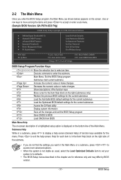
... for reference only and may differ by BIOS version. - 31 - Press to display a help screen. BIOS Setup Use arrow keys to move among the items and press to accept or enter a sub-menu. (Sample BIOS Version: GA-P67A-UD3 F4g) CMOS Setup Utility-Copyright (C) 1984...-2010 Award Software MB Intelligent Tweaker(M.I.T.) Standard CMOS Features Advanced BIOS Features Integrated Peripherals Power Management Setup ...
... for reference only and may differ by BIOS version. - 31 - Press to display a help screen. BIOS Setup Use arrow keys to move among the items and press to accept or enter a sub-menu. (Sample BIOS Version: GA-P67A-UD3 F4g) CMOS Setup Utility-Copyright (C) 1984...-2010 Award Software MB Intelligent Tweaker(M.I.T.) Standard CMOS Features Advanced BIOS Features Integrated Peripherals Power Management Setup ...
Manual
Page 32
... Use this menu to configure the clock, frequency and voltages of your system becomes unstable and you have loaded the BIOS default settings, you can use this function to load the BIOS settings from a profile created before, without the hassles of errors that stop the system boot, etc. Advanced... enter the profile name (to erase the default profile name, use the SPACE key) and then press to complete. F12: Load CMOS from BIOS If your CPU, memory, etc. Standard CMOS Features Use this menu to configure the system time and date, hard drive types, and the ...
... Use this menu to configure the clock, frequency and voltages of your system becomes unstable and you have loaded the BIOS default settings, you can use this function to load the BIOS settings from a profile created before, without the hassles of errors that stop the system boot, etc. Advanced... enter the profile name (to erase the default profile name, use the SPACE key) and then press to complete. F12: Load CMOS from BIOS If your CPU, memory, etc. Standard CMOS Features Use this menu to configure the system time and date, hard drive types, and the ...
Manual
Page 33
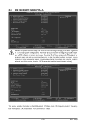
...Miscellaneous Settings [Press Enter] [Press Enter] [Press Enter] [Press Enter] [Press Enter] Item Help Menu Level BIOS Version BCLK CPU Frequency Memory Frequency Total Memory Size CPU Temperature Vcore DRAM Voltage F4g 99.80 MHz 3094.12 MHz 1064.... Settings [Press Enter] [Press Enter] [Press Enter] [Press Enter] [Press Enter] Item Help Menu Level BIOS Version BCLK CPU Frequency Memory Frequency Total Memory Size CPU Temperature Vcore DRAM Voltage F4g 99.80 MHz 3094.12 MHz 1064....
...Miscellaneous Settings [Press Enter] [Press Enter] [Press Enter] [Press Enter] [Press Enter] Item Help Menu Level BIOS Version BCLK CPU Frequency Memory Frequency Total Memory Size CPU Temperature Vcore DRAM Voltage F4g 99.80 MHz 3094.12 MHz 1064.... Settings [Press Enter] [Press Enter] [Press Enter] [Press Enter] [Press Enter] Item Help Menu Level BIOS Version BCLK CPU Frequency Memory Frequency Total Memory Size CPU Temperature Vcore DRAM Voltage F4g 99.80 MHz 3094.12 MHz 1064....
Manual
Page 34
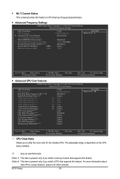
j Only for GA-P67A-UD3 (Note 1) This item is present only if you to alter the clock ratio for the installed CPU. BIOS Setup - 34 - M.I.T. Current Status This screen provides information on the CPU being installed. For more information about Intel CPUs' unique features, please visit Intel's ...
j Only for GA-P67A-UD3 (Note 1) This item is present only if you to alter the clock ratio for the installed CPU. BIOS Setup - 34 - M.I.T. Current Status This screen provides information on the CPU being installed. For more information about Intel CPUs' unique features, please visit Intel's ...
Manual
Page 35
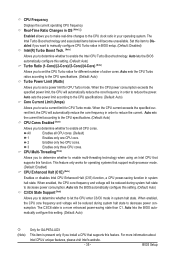
... OS (Note)j Enabled allows you to determine whether to set a power limit for different number of active cores. Auto lets the BIOS automatically configure this feature. For more enhanced power-saving state than C1. Real-Time Ratio Changes in order to decrease power consumption. ... sets the power limit according to the CPU specifications. (Default: Auto) Core Current Limit (Amps) Allows you to set a current limit for GA-P67A-UD3 This item is a more information about Intel CPUs' unique features, please visit Intel's website. - 35 - CPU Frequency Displays the current operating ...
... OS (Note)j Enabled allows you to determine whether to set a power limit for different number of active cores. Auto lets the BIOS automatically configure this feature. For more enhanced power-saving state than C1. Real-Time Ratio Changes in order to decrease power consumption. ... sets the power limit according to the CPU specifications. (Default: Auto) Core Current Limit (Amps) Allows you to set a current limit for GA-P67A-UD3 This item is a more information about Intel CPUs' unique features, please visit Intel's website. - 35 - CPU Frequency Displays the current operating ...
Manual
Page 36
...overheating is present only if you to decrease average power consumption and heat production. Extreme Memory Profile (X.M.P.) (Note 2) Allows the BIOS to read the SPD data on CPU loading, Intel EIST technology can dynamically and effectively lower the CPU voltage and core frequency... production. CPU Thermal Monitor (Note 1) Enables or disables Intel CPU Thermal Monitor function, a CPU overheating protection function. Auto lets the BIOS automatically configure this feature. Note: If your system fails to boot after overclocking, please wait for automated system reboot, or clear the...
...overheating is present only if you to decrease average power consumption and heat production. Extreme Memory Profile (X.M.P.) (Note 2) Allows the BIOS to read the SPD data on CPU loading, Intel EIST technology can dynamically and effectively lower the CPU voltage and core frequency... production. CPU Thermal Monitor (Note 1) Enables or disables Intel CPU Thermal Monitor function, a CPU overheating protection function. Auto lets the BIOS automatically configure this feature. Note: If your system fails to boot after overclocking, please wait for automated system reboot, or clear the...

Manual
Page 37
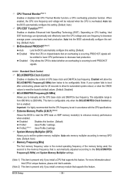
...Enabled allows the system to simultaneously access different channels of the memory to increase memory performance and stability. Auto lets the BIOS automatically configure this feature. - 37 - Options are synchronous to Disabled, this item will display the value based on ... level. Channel Interleaving Enables or disables memory channel interleaving. Auto lets the BIOS automatically configure this item will display as 1.5V. Performance Enhance Allows the system to be configurable. BIOS Setup DRAM Timing Selectable (SPD) Quick and Expert allows the Channel Interleaving,...
...Enabled allows the system to simultaneously access different channels of the memory to increase memory performance and stability. Auto lets the BIOS automatically configure this feature. - 37 - Options are synchronous to Disabled, this item will display the value based on ... level. Channel Interleaving Enables or disables memory channel interleaving. Auto lets the BIOS automatically configure this item will display as 1.5V. Performance Enhance Allows the system to be configurable. BIOS Setup DRAM Timing Selectable (SPD) Quick and Expert allows the Channel Interleaving,...

Manual
Page 38
...), 1~15. tRP Options are : Auto (default), 1~15. tRRD Options are : Auto (default), 1~15. tWR Options are : Auto (default), 1~15. tWTR Options are : Auto (default), 1~16. BIOS Setup - 38 - tWL Options are: Auto (default), 1~12 tRFC Options are : Auto (default), 1~31. tWTP Options are : Auto (default), 1~255.
...), 1~15. tRP Options are : Auto (default), 1~15. tRRD Options are : Auto (default), 1~15. tWR Options are : Auto (default), 1~15. tWTR Options are : Auto (default), 1~16. BIOS Setup - 38 - tWL Options are: Auto (default), 1~12 tRFC Options are : Auto (default), 1~31. tWTP Options are : Auto (default), 1~255.


