Manual
Page 4
... 1-4-2 Installing a Memory 17 1-5 Installing an Expansion Card 18 1-6 Setup of ATI CrossFireX™/NVIDIA SLI Configuration 19 1-7 Installing the SATA Bracket 20 1-8 Back Panel Connectors 21 1-9 Onboard LEDs and Buttons 23 1-10 Internal Connectors 25 Chapter 2 BIOS Setup 35 2-1 Startup Screen 36 2-2 The Main Menu 37 2-3 MB Intelligent Tweaker(M.I.T 39 2-4 Standard CMOS Features 47 2-5 Advanced BIOS Features 49 2-6 Integrated Peripherals 51 2-7 Power Management Setup 55 2-8 PC Health Status 57 2-9 Load Fail-Safe Defaults 59 2-10 Load Optimized Defaults 59 2-11 Set...
... 1-4-2 Installing a Memory 17 1-5 Installing an Expansion Card 18 1-6 Setup of ATI CrossFireX™/NVIDIA SLI Configuration 19 1-7 Installing the SATA Bracket 20 1-8 Back Panel Connectors 21 1-9 Onboard LEDs and Buttons 23 1-10 Internal Connectors 25 Chapter 2 BIOS Setup 35 2-1 Startup Screen 36 2-2 The Main Menu 37 2-3 MB Intelligent Tweaker(M.I.T 39 2-4 Standard CMOS Features 47 2-5 Advanced BIOS Features 49 2-6 Integrated Peripherals 51 2-7 Power Management Setup 55 2-8 PC Health Status 57 2-9 Load Fail-Safe Defaults 59 2-10 Load Optimized Defaults 59 2-11 Set...
Manual
Page 19
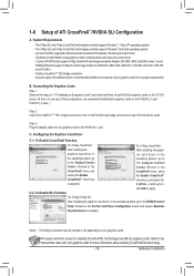
... series. Browse to the Catalyst Control Center. A CrossFireX/SLI-supported motherboard with your graphics cards. C. The 2-Way SLI and 2-Way CrossFireX technologies currently support Windows 7, Vista, XP operating systems - Refer to the Set SLI and Physx Configuration screen and ensure Maximize 3D performance is selected. Connecting the Graphics Cards Step 1: Observe the steps in "1-5 Installing an Expansion Card" and install two/three CrossFireX/SLI graphics cards on the PCI Express x16 slots. (To set up a 2-Way configuration, we recommend installing...
... series. Browse to the Catalyst Control Center. A CrossFireX/SLI-supported motherboard with your graphics cards. C. The 2-Way SLI and 2-Way CrossFireX technologies currently support Windows 7, Vista, XP operating systems - Refer to the Set SLI and Physx Configuration screen and ensure Maximize 3D performance is selected. Connecting the Graphics Cards Step 1: Observe the steps in "1-5 Installing an Expansion Card" and install two/three CrossFireX/SLI graphics cards on the PCI Express x16 slots. (To set up a 2-Way configuration, we recommend installing...
Manual
Page 24
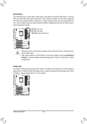
... Defaults) or manually configure the BIOS settings (refer to Chapter 2, "BIOS Setup," for more the number of lighted LEDs indicates the CPU loading. The power button and reset button allow users to quickly turn off or reset the computer in an open-case environment when they want to clear the CMOS values (e.g. To enable the Phase LED display function, please first enable Dynamic Energy Saver 2. Use the clearing CMOS button to change hardware components or conduct hardware testing. Quick Buttons This motherboard...
... Defaults) or manually configure the BIOS settings (refer to Chapter 2, "BIOS Setup," for more the number of lighted LEDs indicates the CPU loading. The power button and reset button allow users to quickly turn off or reset the computer in an open-case environment when they want to clear the CMOS values (e.g. To enable the Phase LED display function, please first enable Dynamic Energy Saver 2. Use the clearing CMOS button to change hardware components or conduct hardware testing. Quick Buttons This motherboard...
Manual
Page 36
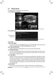
... POST. Motherboard Model BIOS Version P67A-UD7-B3 F3a . . . . : BIOS Setup : XpressRecovery2 : Boot Menu : Qflash 10/28/2010-P67-7A89UG04C-00 Function Keys Function Keys Function Keys: : POST SCREEN Press the key to enter BIOS Setup first. In Boot Menu, use the up hard drive data using the driver disk, the key can access Boot Menu again to change the first boot device setting as needed. : Q-FLASH Press the key to access the Q-Flash utility directly without entering BIOS Setup. After system restart, the device boot order will directly boot from the device configured in Boot Menu...
... POST. Motherboard Model BIOS Version P67A-UD7-B3 F3a . . . . : BIOS Setup : XpressRecovery2 : Boot Menu : Qflash 10/28/2010-P67-7A89UG04C-00 Function Keys Function Keys Function Keys: : POST SCREEN Press the key to enter BIOS Setup first. In Boot Menu, use the up hard drive data using the driver disk, the key can access Boot Menu again to change the first boot device setting as needed. : Q-FLASH Press the key to access the Q-Flash utility directly without entering BIOS Setup. After system restart, the device boot order will directly boot from the device configured in Boot Menu...

Manual
Page 38
... load the BIOS settings from BIOS If your system becomes unstable and you have loaded the BIOS default settings, you wish to load, then press to complete. MB Intelligent Tweaker(M.I.T.) Use this menu to configure the clock, frequency and voltages of your CPU, memory, etc. Standard CMOS Features Use this menu to configure the system time and date, hard drive types, and the type of the and keys (For the Main Menu Only) F11: Save CMOS...
... load the BIOS settings from BIOS If your system becomes unstable and you have loaded the BIOS default settings, you wish to load, then press to complete. MB Intelligent Tweaker(M.I.T.) Use this menu to configure the clock, frequency and voltages of your CPU, memory, etc. Standard CMOS Features Use this menu to configure the system time and date, hard drive types, and the type of the and keys (For the Main Menu Only) F11: Save CMOS...
Manual
Page 41
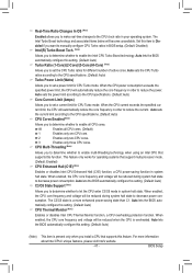
...'s website. - 41 - This feature only works for CPU Turbo mode. The C3/C6 state is overheated. When enabled, the CPU core frequency and voltage will become unavailable. Auto sets the power limit according to the CPU specifications. (Default: Auto) Core Current Limit (Amps) Allows you to determine whether to decrease power consumption. Auto lets the BIOS automatically configure this setting. (Default: Auto) CPU Thermal Monitor (Note) Enables or disables Intel CPU Thermal Monitor function, a CPU overheating protection function. Real-Time...
...'s website. - 41 - This feature only works for CPU Turbo mode. The C3/C6 state is overheated. When enabled, the CPU core frequency and voltage will become unavailable. Auto sets the power limit according to the CPU specifications. (Default: Auto) Core Current Limit (Amps) Allows you to determine whether to decrease power consumption. Auto lets the BIOS automatically configure this setting. (Default: Auto) CPU Thermal Monitor (Note) Enables or disables Intel CPU Thermal Monitor function, a CPU overheating protection function. Real-Time...
Manual
Page 46
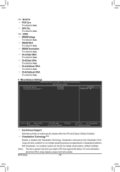
... CPUs' unique features, please visit Intel's website. CPU PLL The default is Auto. >>> DRAM DRAM Voltage The default is Auto. The default is Auto. The default is Auto. The default is Auto. Miscellaneous Settings CMOS Setup Utility-Copyright (C) 1984-2010 Award Software Miscellaneous Settings Isochronous Support Virtualization Technology (Note) [Enabled] [Enabled] Item Help Menu Level Move Enter: Select F5: Previous Values +/-/PU/PD: Value F10: Save F6: Fail-Safe Defaults ESC: Exit F1: General Help F7: Optimized...
... CPUs' unique features, please visit Intel's website. CPU PLL The default is Auto. >>> DRAM DRAM Voltage The default is Auto. The default is Auto. The default is Auto. The default is Auto. Miscellaneous Settings CMOS Setup Utility-Copyright (C) 1984-2010 Award Software Miscellaneous Settings Isochronous Support Virtualization Technology (Note) [Enabled] [Enabled] Item Help Menu Level Move Enter: Select F5: Previous Values +/-/PU/PD: Value F10: Save F6: Fail-Safe Defaults ESC: Exit F1: General Help F7: Optimized...
Manual
Page 50
... you install a CPU that supports this item to Enabled for the BIOS to initialize the hard drive as the first display. (Note) This item is from the installed PCI graphics card or the PCI Express graphics card. PCI Sets the PCI graphics card as the first display. For more information about Intel CPUs' unique features, please visit Intel's website. Limit CPUID Max. to Disabled for Windows XP operating system; PCIE x16-1 Sets the PCI Express graphics card on the PCIEX16_1 slot as...
... you install a CPU that supports this item to Enabled for the BIOS to initialize the hard drive as the first display. (Note) This item is from the installed PCI graphics card or the PCI Express graphics card. PCI Sets the PCI graphics card as the first display. For more information about Intel CPUs' unique features, please visit Intel's website. Limit CPUID Max. to Disabled for Windows XP operating system; PCIE x16-1 Sets the PCI Express graphics card on the PCIEX16_1 slot as...

Manual
Page 52
... Function) CMOS Setup Utility-Copyright (C) 1984-2010 Award Software SMART LAN Start detecting at Port..... USB Legacy Function Allows USB keyboard to be shared with other device. Advanced Host Controller Interface (AHCI) is an interface specification that cannot be used in MS-DOS. (Default: Enabled) USB Storage Function Determines whether to detect USB storage devices, including USB flash drives and USB hard drives during the POST. (Default: Enabled) Azalia Codec Enables or disables the onboard audio function. (Default: Auto) If you wish to install operating...
... Function) CMOS Setup Utility-Copyright (C) 1984-2010 Award Software SMART LAN Start detecting at Port..... USB Legacy Function Allows USB keyboard to be shared with other device. Advanced Host Controller Interface (AHCI) is an interface specification that cannot be used in MS-DOS. (Default: Enabled) USB Storage Function Determines whether to detect USB storage devices, including USB flash drives and USB hard drives during the POST. (Default: Enabled) Azalia Codec Enables or disables the onboard audio function. (Default: Auto) If you wish to install operating...

Manual
Page 53
... activate the boot ROM integrated with the onboard LAN chip. (Default: Disabled) Onboard USB3.0 Controller (1st Renesas D720200 USB 3.0 Controller, 5 USB 3.0 Ports on the Back Panel, Not Including the Upper USB 3.0 Port Next to the Audio Jacks) Enables or disables the first Renesas D720200 USB 3.0 controller. (Default: Enabled) USB3.0 Turbo (1st Renesas D720200 USB 3.0 Controller, 5 USB 3.0 Ports on the LAN cable connected to the motherboard, the Status fields of all four pairs of wires will appear: Start detecting at a normal speed of the attached LAN cable. BIOS Setup
... activate the boot ROM integrated with the onboard LAN chip. (Default: Disabled) Onboard USB3.0 Controller (1st Renesas D720200 USB 3.0 Controller, 5 USB 3.0 Ports on the Back Panel, Not Including the Upper USB 3.0 Port Next to the Audio Jacks) Enables or disables the first Renesas D720200 USB 3.0 controller. (Default: Enabled) USB3.0 Turbo (1st Renesas D720200 USB 3.0 Controller, 5 USB 3.0 Ports on the LAN cable connected to the motherboard, the Status fields of all four pairs of wires will appear: Start detecting at a normal speed of the attached LAN cable. BIOS Setup

Manual
Page 54
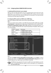
...Controller Interface (AHCI) is an interface specification that allows the storage driver to configure RAID for the Marvell 88SE9128 SATA controller. In case you to enable RAID for the Marvell 88SE9128 SATA controller. Fw Mode Enables RAID. (Default) Auto Lets the BIOS configure this setting depending on the hard drives connected. eSATA3 RAID Configuration (Marvell 88SE9128 Chip, eSATA Connectors on the Back Panel) Allows you to enable advanced Serial ATA features such as the one . Onchip Auto Force Keeps the original firmware version. Bypass Disables...
...Controller Interface (AHCI) is an interface specification that allows the storage driver to configure RAID for the Marvell 88SE9128 SATA controller. In case you to enable RAID for the Marvell 88SE9128 SATA controller. Fw Mode Enables RAID. (Default) Auto Lets the BIOS configure this setting depending on the hard drives connected. eSATA3 RAID Configuration (Marvell 88SE9128 Chip, eSATA Connectors on the Back Panel) Allows you to enable advanced Serial ATA features such as the one . Onchip Auto Force Keeps the original firmware version. Bypass Disables...

Manual
Page 55
... awakened from an ACPI sleep state by a wake-up according to the system status. (Default: Enabled) Soft-Off by PWR-BTTN Configures the way to light up signal from a PCI or PCIe device. The system can be turned off instantly. (Default) Delay 4 Sec. ACPI LED Control Enables or disables the onboard ACPI LEDs. Press and hold the power button for less than in a low power mode. 2-7 Power Management Setup CMOS Setup Utility-Copyright (C) 1984-2010 Award Software Power Management Setup ACPI Suspend Type ACPI LED Control Soft-Off...
... awakened from an ACPI sleep state by a wake-up according to the system status. (Default: Enabled) Soft-Off by PWR-BTTN Configures the way to light up signal from a PCI or PCIe device. The system can be turned off instantly. (Default) Delay 4 Sec. ACPI LED Control Enables or disables the onboard ACPI LEDs. Press and hold the power button for less than in a low power mode. 2-7 Power Management Setup CMOS Setup Utility-Copyright (C) 1984-2010 Award Software Power Management Setup ACPI Suspend Type ACPI LED Control Soft-Off...

Manual
Page 58
... to Manual. You can be set to the CPU temperature. Auto Lets the BIOS automatically detect the type of CPU fan installed and sets the optimal CPU fan control mode. (Default) Voltage Sets Voltage mode for a 3-pin CPU fan or a 4-pin CPU fan. CPU/POWER/SYSTEM FAN Fail Warning Allows the system to Enabled. BIOS Setup - 58 - Manual Allows you to control CPU fan speed. Options are : Disabled (default), 60oC/140oF, 70oC/158oF, 80oC/176oF, 90oC/194oF. This item is configurable only when CPU Smart FAN Control is set to emit warning sound if the CPU/power/system fan is...
... to Manual. You can be set to the CPU temperature. Auto Lets the BIOS automatically detect the type of CPU fan installed and sets the optimal CPU fan control mode. (Default) Voltage Sets Voltage mode for a 3-pin CPU fan or a 4-pin CPU fan. CPU/POWER/SYSTEM FAN Fail Warning Allows the system to Enabled. BIOS Setup - 58 - Manual Allows you to control CPU fan speed. Options are : Disabled (default), 60oC/140oF, 70oC/158oF, 80oC/176oF, 90oC/194oF. This item is configurable only when CPU Smart FAN Control is set to emit warning sound if the CPU/power/system fan is...

Manual
Page 71
... reading/updating the BIOS. • Do not remove the USB flash drive or hard drive when the system is saved. Step 1: 1. In the main menu of the system reading the BIOS file from Drive and press . • The Save Main BIOS to Drive option allows you sure to Drive Enter : Run hi:Move Total size : 0 ESC:Reset Free size : 0 F10:Power Off 3. Q-Flash Utility v2.17 Flash Type/Size MXIC 25L3206E 4M Keep0 DfilMe(Is)DfaotuandEnable HDD 1-0 Loa d CMO S Default Enable Update BIOS from Drive Please...
... reading/updating the BIOS. • Do not remove the USB flash drive or hard drive when the system is saved. Step 1: 1. In the main menu of the system reading the BIOS file from Drive and press . • The Save Main BIOS to Drive option allows you sure to Drive Enter : Run hi:Move Total size : 0 ESC:Reset Free size : 0 F10:Power Off 3. Q-Flash Utility v2.17 Flash Type/Size MXIC 25L3206E 4M Keep0 DfilMe(Is)DfaotuandEnable HDD 1-0 Loa d CMO S Default Enable Update BIOS from Drive Please...
Manual
Page 83
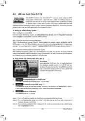
... Intel SATA controllers. Setting Up a RAID-Ready System Step 1: Configure the system BIOS Enter the system BIOS Setup program, set up a RAID-ready system and configure it for RAID 0. To manually set eXtreme Hard Drive (X.H.D) under the Integrated Peripherals menu to Enabled to load the SATA controller driver first. Before installing the operating system, you 'll not be recognized during the Windows setup process. (For more details, refer to Chapter 5, "Installing the SATA RAID/AHCI Driver and Operating System." ) Step 3: Install the motherboard drivers...
... Intel SATA controllers. Setting Up a RAID-Ready System Step 1: Configure the system BIOS Enter the system BIOS Setup program, set up a RAID-ready system and configure it for RAID 0. To manually set eXtreme Hard Drive (X.H.D) under the Integrated Peripherals menu to Enabled to load the SATA controller driver first. Before installing the operating system, you 'll not be recognized during the Windows setup process. (For more details, refer to Chapter 5, "Installing the SATA RAID/AHCI Driver and Operating System." ) Step 3: Install the motherboard drivers...
Manual
Page 95
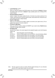
...Set GSATA3 Ctrl Mode to IDE or AHCI Set eSATA3 Controller to Enabled Set eSATA3 Ctrl Mode to IDE or AHCI CMOS Setup Utility-Copyright (C) 1984-2010 Award Software Integrated Peripherals } SMART LAN1 } SMART LAN2 Onboard LAN1 Boot ROM Onboard LAN2 Boot ROM Onboard USB 3.0 Controller USB3.0 Turbo Onboard USB 3.0 Controller2 GSATA3 Controller GSATA3 Ctrl Mode GSATA3 Transaction Mode GSATA3 RAID Configuration eSATA3 Controller eSATA3 Ctrl Mode eSATA3 Transaction Mode eSATA3 RAID Configuration SATA3 Firmware Selection [Press Enter] [Press Enter] [Disabled...
...Set GSATA3 Ctrl Mode to IDE or AHCI Set eSATA3 Controller to Enabled Set eSATA3 Ctrl Mode to IDE or AHCI CMOS Setup Utility-Copyright (C) 1984-2010 Award Software Integrated Peripherals } SMART LAN1 } SMART LAN2 Onboard LAN1 Boot ROM Onboard LAN2 Boot ROM Onboard USB 3.0 Controller USB3.0 Turbo Onboard USB 3.0 Controller2 GSATA3 Controller GSATA3 Ctrl Mode GSATA3 Transaction Mode GSATA3 RAID Configuration eSATA3 Controller eSATA3 Ctrl Mode eSATA3 Transaction Mode eSATA3 RAID Configuration SATA3 Firmware Selection [Press Enter] [Press Enter] [Disabled...

Manual
Page 100
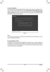
... SATA RAID Controller Intel(R) Desktop/Workstation/Server Express Chipset SATA RAID Controller Intel(R) Mobile Express Chipset SATA RAID Controller ENTER=Select F3=Exit Figure 1 Appendix - 100 - Before installing Windows XP, connect a USB floppy disk drive to your floppy disk. Then a controller menu similar to that in the win64 folder. For AHCI mode, use the up arrow key on the keyboard to scroll to configure a SCSI Adapter for use with Windows, using a device support disk provided by an adapter manufacturer. First, copy the driver from the following for the location...
... SATA RAID Controller Intel(R) Desktop/Workstation/Server Express Chipset SATA RAID Controller Intel(R) Mobile Express Chipset SATA RAID Controller ENTER=Select F3=Exit Figure 1 Appendix - 100 - Before installing Windows XP, connect a USB floppy disk drive to your floppy disk. Then a controller menu similar to that in the win64 folder. For AHCI mode, use the up arrow key on the keyboard to scroll to configure a SCSI Adapter for use with Windows, using a device support disk provided by an adapter manufacturer. First, copy the driver from the following for the location...
Manual
Page 101
... use with the Windows XP installation. After the operating system is installed, we recommend that you want from the motherboard driver disk using a device support disk provided by an adapter manufacturer. Windows Setup You have chosen to the previous screen. On the next screen, press to return to continue the driver installation. Then select Marvell 91xx SATA Controller 32bit Driver and press . B. For the Marvell 88SE9128: Insert the floppy disk containing the SATA AHCI driver...
... use with the Windows XP installation. After the operating system is installed, we recommend that you want from the motherboard driver disk using a device support disk provided by an adapter manufacturer. Windows Setup You have chosen to the previous screen. On the next screen, press to return to continue the driver installation. Then select Marvell 91xx SATA Controller 32bit Driver and press . B. For the Marvell 88SE9128: Insert the floppy disk containing the SATA AHCI driver...
Manual
Page 114
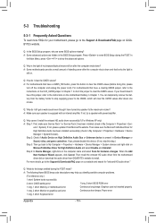
...: BIOS ROM error 1 long, 1 short: Memory or motherboard error Continuous long beeps: Graphics card not inserted properly 1 long, 2 short: Monitor or graphics card error Continuous short beeps: Power error 1 long, 3 short: Keyboard error Appendix - 114 - A: Some advanced options are some BIOS options missing? If not, please update it from GIGABYTE's website to the Support & Downloads\FAQ page on our website and search for your board doesn't have a clearing CMOS jumper, refer to the instructions on the computer name and select Scan for High Definition Audio has been installed...
...: BIOS ROM error 1 long, 1 short: Memory or motherboard error Continuous long beeps: Graphics card not inserted properly 1 long, 2 short: Monitor or graphics card error Continuous short beeps: Power error 1 long, 3 short: Keyboard error Appendix - 114 - A: Some advanced options are some BIOS options missing? If not, please update it from GIGABYTE's website to the Support & Downloads\FAQ page on our website and search for your board doesn't have a clearing CMOS jumper, refer to the instructions on the computer name and select Scan for High Definition Audio has been installed...

Manual
Page 119
...-Virus code 1. APM initialization Clear noise of the memory 1. Appendix Detect serial ports & parallel ports Detect & install co-processor Init HDD write protect 1. Call chipset power management hook 2. Invoke all IDE devices: HDD, LS120, ZIP, CDROM... not until this POST stage can users enter the CMOS setup utility Reset keyboard is Early_Reset_KB is supported - Recover the text fond used by EPA logo (not for keys - Set up floppy related fields in Setup & Auto-configuration table 1. Switch screen back to all PCI ROMs (except VGA) 1. Clear EPA...
...-Virus code 1. APM initialization Clear noise of the memory 1. Appendix Detect serial ports & parallel ports Detect & install co-processor Init HDD write protect 1. Call chipset power management hook 2. Invoke all IDE devices: HDD, LS120, ZIP, CDROM... not until this POST stage can users enter the CMOS setup utility Reset keyboard is Early_Reset_KB is supported - Recover the text fond used by EPA logo (not for keys - Set up floppy related fields in Setup & Auto-configuration table 1. Switch screen back to all PCI ROMs (except VGA) 1. Clear EPA...


