
Manual
Page 5
... 4-5 Q-Share...71 4-6 Smart 6™ ...72 4-7 Auto Green...76 4-8 eXtreme Hard Drive (X.H.D 77 4-9 Cloud OC...78 Chapter 5 Appendix...79 5-1 Configuring SATA Hard Drive(s 79 5-1-1 Configuring Intel P67 SATA Controllers 79 5-1-2 Configuring Marvell 88SE9128 SATA Controller 87 5-1-3 Installing the SATA RAID/AHCI Driver and Operating System 92 5-2 Configuring Audio Input and Output 99...
... 4-5 Q-Share...71 4-6 Smart 6™ ...72 4-7 Auto Green...76 4-8 eXtreme Hard Drive (X.H.D 77 4-9 Cloud OC...78 Chapter 5 Appendix...79 5-1 Configuring SATA Hard Drive(s 79 5-1-1 Configuring Intel P67 SATA Controllers 79 5-1-2 Configuring Marvell 88SE9128 SATA Controller 87 5-1-3 Installing the SATA RAID/AHCI Driver and Operating System 92 5-2 Configuring Audio Input and Output 99...

Manual
Page 7
... Marvell 88SE9128 R_USB30 LGA1155 CPU_FAN PHASE LED PWR_FAN USB_LAN Renesas D720200 AUDIO GA-P67A-UD4 ATX F_AUDIO DDR3_1 DDR3_2 DDR3_3 DDR3_4 Realtek RTL8111E PCIEX1_1 (Note) PCIEX16 PCIEX1_2 CODEC PCIEX1_3 BAT SPDIF_O PCIEX8 iTE PCI1 IT8728 PCI2 COMA SYS_FAN2 F_USB3 F_USB2 Intel® P67 iTE IT8892 Bridge F_USB1 Renesas D720200 F_USB30 CLR_CMOS B_BIOS M_BIOS SATA3_1...
... Marvell 88SE9128 R_USB30 LGA1155 CPU_FAN PHASE LED PWR_FAN USB_LAN Renesas D720200 AUDIO GA-P67A-UD4 ATX F_AUDIO DDR3_1 DDR3_2 DDR3_3 DDR3_4 Realtek RTL8111E PCIEX1_1 (Note) PCIEX16 PCIEX1_2 CODEC PCIEX1_3 BAT SPDIF_O PCIEX8 iTE PCI1 IT8728 PCI2 COMA SYS_FAN2 F_USB3 F_USB2 Intel® P67 iTE IT8892 Bridge F_USB1 Renesas D720200 F_USB30 CLR_CMOS B_BIOS M_BIOS SATA3_1...

Manual
Page 8
GA-P67A-UD4 Motherboard Block Diagram PCIe CLK (100 MHz) 1 PCI Express x16 or 2 PCI Express x8 LGA1155 CPU CPU CLK+/- (100 MHz) DDR3 2133/1866/1600/1333/... Channel Memory x16 x8 Switch DMI Interface PCI Express Bus 2 SATA 6Gb/s LAN RJ45 Marvell Realtek 88SE9128 RTL8111E PCI Express Bus x1 x1 Intel® P67 PCIe CLK (100 MHz) x1 x1 x1 x1 3 PCI Express x1 iTE IT8892 Bridge PCI Bus CODEC 2 USB 3.0/2.0 2 USB 3.0/2.0 Renesas D720200 Renesas D720200 x1 x1...
GA-P67A-UD4 Motherboard Block Diagram PCIe CLK (100 MHz) 1 PCI Express x16 or 2 PCI Express x8 LGA1155 CPU CPU CLK+/- (100 MHz) DDR3 2133/1866/1600/1333/... Channel Memory x16 x8 Switch DMI Interface PCI Express Bus 2 SATA 6Gb/s LAN RJ45 Marvell Realtek 88SE9128 RTL8111E PCI Express Bus x1 x1 Intel® P67 PCIe CLK (100 MHz) x1 x1 x1 x1 3 PCI Express x1 iTE IT8892 Bridge PCI Bus CODEC 2 USB 3.0/2.0 2 USB 3.0/2.0 Renesas D720200 Renesas D720200 x1 x1...

Manual
Page 10
...SATA RAID 0, RAID 1, RAID 5, and RAID 10 * When a RAID set may vary depending on the back panel supporting up to GIGABYTE's website for the latest supported memory speeds and memory modules) Realtek ALC892 codec High Definition Audio 2/4/5.1/7.1-channel Support for Dolby® Home ...Mbit) Expansion Slots 1 x PCI Express x16 slot, running at x8 (PCIEX8) * The PCIEX8 slot shares bandwidth with CPU Intel® P67 Express Chipset Memory Audio 4 x 1.5V DDR3 DIMM sockets supporting up to 16 GB of the RAID set...
...SATA RAID 0, RAID 1, RAID 5, and RAID 10 * When a RAID set may vary depending on the back panel supporting up to GIGABYTE's website for the latest supported memory speeds and memory modules) Realtek ALC892 codec High Definition Audio 2/4/5.1/7.1-channel Support for Dolby® Home ...Mbit) Expansion Slots 1 x PCI Express x16 slot, running at x8 (PCIEX8) * The PCIEX8 slot shares bandwidth with CPU Intel® P67 Express Chipset Memory Audio 4 x 1.5V DDR3 DIMM sockets supporting up to 16 GB of the RAID set...

Manual
Page 25
...If more than two hard BUG drives are compatible with SATA 1.5Gb/s stan- RT • A RAID 5 configuration requires at least two hard drives. The P67 controller supports RAID 0, RAID 1, RAID 5, and RAID 10. SATA3_1 7 1 7 1 SATA3_0 G.QBOFM Pin No. 1 2 3 4 5 6 7 ...Definition GND TXP TXN GND RXN RXP GND 8) SATA2_2/3/4/5 (SATA 3Gb/s Connectors, Controlled by P67 Chipset) The SATA connectors conform to SATA 6Gb/s standard and are compatible with the SATA2_2/3/4/5 connector . (Note) Refer to Chapter 5, "Configuring SATA Hard Drive(s),"...
...If more than two hard BUG drives are compatible with SATA 1.5Gb/s stan- RT • A RAID 5 configuration requires at least two hard drives. The P67 controller supports RAID 0, RAID 1, RAID 5, and RAID 10. SATA3_1 7 1 7 1 SATA3_0 G.QBOFM Pin No. 1 2 3 4 5 6 7 ...Definition GND TXP TXN GND RXN RXP GND 8) SATA2_2/3/4/5 (SATA 3Gb/s Connectors, Controlled by P67 Chipset) The SATA connectors conform to SATA 6Gb/s standard and are compatible with the SATA2_2/3/4/5 connector . (Note) Refer to Chapter 5, "Configuring SATA Hard Drive(s),"...
Manual
Page 32
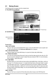
... or to access the Q-Flash utility in Boot Menu is effective for subsequent access to accept. Motherboard Model BIOS Version P67A-UD4 F4f . . . . : BIOS Setup : XpressRecovery2 : Boot Menu : Qflash 11/12/2010-P67-7A89UG01C-00 Function Keys Function Keys Function Keys: : POST SCREEN Press the key to show the BIOS POST screen at...
... or to access the Q-Flash utility in Boot Menu is effective for subsequent access to accept. Motherboard Model BIOS Version P67A-UD4 F4f . . . . : BIOS Setup : XpressRecovery2 : Boot Menu : Qflash 11/12/2010-P67-7A89UG01C-00 Function Keys Function Keys Function Keys: : POST SCREEN Press the key to show the BIOS POST screen at...

Manual
Page 47
...-Safe Defaults ESC: Exit F1: General Help F7: Optimized Defaults eXtreme Hard Drive (Intel P67 Chipset) Enables or disables the X.H.D function for the SATA controllers. For details on using the GIGABYTE X.H.D utility, refer to Chaper 4, "eXtreme Hard Drive (X.H.D)." (Default: Disabled) PCH SATA... Control Mode (Intel P67 Chipset) Enables or disables RAID for the SATA controllers integrated in the Intel P67 Chipset or configures the SATA controllers to...
...-Safe Defaults ESC: Exit F1: General Help F7: Optimized Defaults eXtreme Hard Drive (Intel P67 Chipset) Enables or disables the X.H.D function for the SATA controllers. For details on using the GIGABYTE X.H.D utility, refer to Chaper 4, "eXtreme Hard Drive (X.H.D)." (Default: Disabled) PCH SATA... Control Mode (Intel P67 Chipset) Enables or disables RAID for the SATA controllers integrated in the Intel P67 Chipset or configures the SATA controllers to...

Manual
Page 64
...access Q-Flash. Note: You can update the system BIOS without the need to your motherboard model. 2. P67A-UD4 F4f . . . . : BIOS Setup : XpressRecovery2 : Boot Menu : Qflash 11/12/2010-P67-7A89UG01C-00 Because BIOS flashing is @BIOS™? @BIOS allows you to update the BIOS without having to...USB flash drive or USB hard drive. Award Modular BIOS v6.00PG Copyright (C) 1984-2010, Award Software, Inc. 4-2 BIOS Update Utilities GIGABYTE motherboards provide two unique BIOS update tools, Q-Flash™ and @BIOS™. For the sake of your computer by either pressing the key...
...access Q-Flash. Note: You can update the system BIOS without the need to your motherboard model. 2. P67A-UD4 F4f . . . . : BIOS Setup : XpressRecovery2 : Boot Menu : Qflash 11/12/2010-P67-7A89UG01C-00 Because BIOS flashing is @BIOS™? @BIOS allows you to update the BIOS without having to...USB flash drive or USB hard drive. Award Modular BIOS v6.00PG Copyright (C) 1984-2010, Award Software, Inc. 4-2 BIOS Update Utilities GIGABYTE motherboards provide two unique BIOS update tools, Q-Flash™ and @BIOS™. For the sake of your computer by either pressing the key...

Manual
Page 79
...drive. (Note 1) Skip this motherboard, the SATA3_0, SATA3_1 (Note 3), SATA2_2, SATA2_3, SATA2_4 and SATA2_5 ports are supported by the P67 Chipset.) Then connect the power connector from your computer. Install SATA hard drive(s) in your computer Attach one end of the SATA signal...Required when the SATA controller is more than one hard drive. • Windows 7/Vista/XP setup disk. • Motherboard driver disk. 5-1-1 Configuring Intel P67 SATA Controllers A. Appendix Configure SATA controller mode in RAID BIOS. (Note 1) D. Install the SATA RAID/AHCI driver (Note 2) and operating system. ...
...drive. (Note 1) Skip this motherboard, the SATA3_0, SATA3_1 (Note 3), SATA2_2, SATA2_3, SATA2_4 and SATA2_5 ports are supported by the P67 Chipset.) Then connect the power connector from your computer. Install SATA hard drive(s) in your computer Attach one end of the SATA signal...Required when the SATA controller is more than one hard drive. • Windows 7/Vista/XP setup disk. • Motherboard driver disk. 5-1-1 Configuring Intel P67 SATA Controllers A. Appendix Configure SATA controller mode in RAID BIOS. (Note 1) D. Install the SATA RAID/AHCI driver (Note 2) and operating system. ...

Manual
Page 92
Refer to the following for the location of the driver. • For the Intel P67, copy all of the files in the \BootDrv\Marvell\win32 folder to your floppy disk. To install Windows 64-Bit, copy the files in the ... folder. • For the Marvell 88SE9128, copy all of the files in the \BootDrv\iRST\32Bit folder to your hard drive(s). Step 2: For the Intel P67: Insert the floppy disk containing the SATA RAID/AHCI driver and press . Select the SCSI Adapter you want from the following for use the up...
Refer to the following for the location of the driver. • For the Intel P67, copy all of the files in the \BootDrv\Marvell\win32 folder to your floppy disk. To install Windows 64-Bit, copy the files in the ... folder. • For the Marvell 88SE9128, copy all of the files in the \BootDrv\iRST\32Bit folder to your hard drive(s). Step 2: For the Intel P67: Insert the floppy disk containing the SATA RAID/AHCI driver and press . Select the SCSI Adapter you want from the following for use the up...

Manual
Page 94
...-22LS Serial # 3JT354CP WD-WMAM9W736333 Size 111.7GB 111.7GB Type/Status(Vol ID) Member Disk (0) Member Disk (0) Volumes with a new one .) For the Intel P67: Turn off your computer. • Enabling Automatic Rebuild Step 1: When the message "Press to enter Configuration Utility" appears, press + to fault-tolerant arrays such as...
...-22LS Serial # 3JT354CP WD-WMAM9W736333 Size 111.7GB 111.7GB Type/Status(Vol ID) Member Disk (0) Member Disk (0) Volumes with a new one .) For the Intel P67: Turn off your computer. • Enabling Automatic Rebuild Step 1: When the message "Press to enter Configuration Utility" appears, press + to fault-tolerant arrays such as...
