
Manual
Page 1
GA-P67A-UD3P-B3 LGA1155 socket motherboard for Intel® Core™ i7 processors/ Intel® Core™ i5 processors/Intel® Core™ i3 processors/ Intel® Pentium® processors/Intel® Celeron® processors User's Manual Rev. 1101 12ME-P6AU3PB-1101R
GA-P67A-UD3P-B3 LGA1155 socket motherboard for Intel® Core™ i7 processors/ Intel® Core™ i5 processors/Intel® Core™ i3 processors/ Intel® Pentium® processors/Intel® Celeron® processors User's Manual Rev. 1101 12ME-P6AU3PB-1101R

Manual
Page 2
Motherboard GA-P67A-UD3P-B3 Nov. 08, 2010 Motherboard GA-P67A-UD3P-B3 Nov. 08, 2010
Motherboard GA-P67A-UD3P-B3 Nov. 08, 2010 Motherboard GA-P67A-UD3P-B3 Nov. 08, 2010
Manual
Page 3
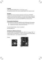
... or by copyright laws and is the property of the motherboard is protected by any means without prior notice. For product-related information, check on our website at: http://www.gigabyte.com Identifying Your Motherboard Revision The revision number on your motherboard revision before updating motherboard BIOS, drivers, or when looking for technical information. Copyright...
... or by copyright laws and is the property of the motherboard is protected by any means without prior notice. For product-related information, check on our website at: http://www.gigabyte.com Identifying Your Motherboard Revision The revision number on your motherboard revision before updating motherboard BIOS, drivers, or when looking for technical information. Copyright...

Manual
Page 4
Table of Contents Box Contents...6 Optional Items...6 GA-P67A-UD3P-B3 Motherboard Layout 7 GA-P67A-UD3P-B3 Motherboard Block Diagram 8 Chapter 1 Hardware Installation 9 1-1 Installation Precautions 9 1-2 Product Specifications 10 1-3 Installing the CPU and CPU Cooler 13 1-3-1 Installing the CPU 13 1-3-2 Installing the CPU Cooler ...
Table of Contents Box Contents...6 Optional Items...6 GA-P67A-UD3P-B3 Motherboard Layout 7 GA-P67A-UD3P-B3 Motherboard Block Diagram 8 Chapter 1 Hardware Installation 9 1-1 Installation Precautions 9 1-2 Product Specifications 10 1-3 Installing the CPU and CPU Cooler 13 1-3-1 Installing the CPU 13 1-3-2 Installing the CPU Cooler ...

Manual
Page 6
The box contents are for reference only. Optional Items 2-port USB 2.0 bracket (Part No. 12CR1-1UB030-5*R) 2-port SATA power cable (Part No. 12CF1-2SERPW-0*R) COM port cable (Part No. 12CF1-1CM001-3*R) - 6 - Box Contents GA-P67A-UD3P-B3 motherboard Motherboard driver disk User's Manual Quick Installation Guide Four SATA cables I/O Shield • The box contents above are subject to change without notice. • The motherboard image is for reference only and the actual items shall depend on the product package you obtain.
The box contents are for reference only. Optional Items 2-port USB 2.0 bracket (Part No. 12CR1-1UB030-5*R) 2-port SATA power cable (Part No. 12CF1-2SERPW-0*R) COM port cable (Part No. 12CF1-1CM001-3*R) - 6 - Box Contents GA-P67A-UD3P-B3 motherboard Motherboard driver disk User's Manual Quick Installation Guide Four SATA cables I/O Shield • The box contents above are subject to change without notice. • The motherboard image is for reference only and the actual items shall depend on the product package you obtain.

Manual
Page 7
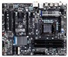
For a longer expansion card, use other expansion slots. - 7 - GA-P67A-UD3P-B3 Motherboard Layout KB_MS_USB R_SPDIF SYS_FAN1 ATX_12V_2X4 R_USB_2 R_USB_1 R_USB30 LGA1155 CPU_FAN PHASE LED PWR_FAN USB_LAN Renesas D720200 AUDIO GA-P67A-UD3P-B3 ATX F_AUDIO DDR3_1 DDR3_2 DDR3_3 DDR3_4 Realtek RTL8111E PCIEX1_1 (Note) PCIEX16 PCIEX1_2 CODEC PCIEX1_3 BAT SPDIF_O PCIEX4 iTE PCI1 IT8728 PCI2 iTE IT8892 Bridge Intel&#...
For a longer expansion card, use other expansion slots. - 7 - GA-P67A-UD3P-B3 Motherboard Layout KB_MS_USB R_SPDIF SYS_FAN1 ATX_12V_2X4 R_USB_2 R_USB_1 R_USB30 LGA1155 CPU_FAN PHASE LED PWR_FAN USB_LAN Renesas D720200 AUDIO GA-P67A-UD3P-B3 ATX F_AUDIO DDR3_1 DDR3_2 DDR3_3 DDR3_4 Realtek RTL8111E PCIEX1_1 (Note) PCIEX16 PCIEX1_2 CODEC PCIEX1_3 BAT SPDIF_O PCIEX4 iTE PCI1 IT8728 PCI2 iTE IT8892 Bridge Intel&#...

Manual
Page 8
GA-P67A-UD3P-B3 Motherboard Block Diagram PCIe CLK (100 MHz) 1 PCI Express x16 LGA1155 CPU CPU CLK+/- (100 MHz) DDR3 2133/1866/1600/1333/1066 MHz Dual Channel Memory ...
GA-P67A-UD3P-B3 Motherboard Block Diagram PCIe CLK (100 MHz) 1 PCI Express x16 LGA1155 CPU CPU CLK+/- (100 MHz) DDR3 2133/1866/1600/1333/1066 MHz Dual Channel Memory ...

Manual
Page 9
...electrostatic discharge (ESD). These stickers are required for warranty validation. • Always remove the AC power by unplugging the power cord from the motherboard, make sure the power supply has been turned off. • Before turning on the power, make sure the power supply voltage has been...system components as well as physical harm to the user. • If you are connected tightly and securely. • When handling the motherboard, avoid touching any installation steps or have it on top of an antistatic pad or within an electrostatic shielding container. • Before unplugging...
...electrostatic discharge (ESD). These stickers are required for warranty validation. • Always remove the AC power by unplugging the power cord from the motherboard, make sure the power supply has been turned off. • Before turning on the power, make sure the power supply voltage has been...system components as well as physical harm to the user. • If you are connected tightly and securely. • When handling the motherboard, avoid touching any installation steps or have it on top of an antistatic pad or within an electrostatic shielding container. • Before unplugging...

Manual
Page 12
...;Š Support for Xpress Install ŠŠ Support for Xpress Recovery2 ŠŠ Support for EasyTune * Available functions in EasyTune may differ by motherboard model. ŠŠ Support for Dynamic Energy Saver™ 2 ŠŠ Support for Smart 6™ ŠŠ Support for Auto Green...; Support for Microsoft® Windows® 7/Vista/XP Form Factor ŠŠ ATX Form Factor; 30.5cm x 24.4cm * GIGABYTE reserves the right to make any changes to the product specifications and product-related information without prior notice. Hardware Installation - 12 -
...;Š Support for Xpress Install ŠŠ Support for Xpress Recovery2 ŠŠ Support for EasyTune * Available functions in EasyTune may differ by motherboard model. ŠŠ Support for Dynamic Energy Saver™ 2 ŠŠ Support for Smart 6™ ŠŠ Support for Auto Green...; Support for Microsoft® Windows® 7/Vista/XP Form Factor ŠŠ ATX Form Factor; 30.5cm x 24.4cm * GIGABYTE reserves the right to make any changes to the product specifications and product-related information without prior notice. Hardware Installation - 12 -

Manual
Page 13
...grease on the surface of the CPU. • Do not turn on the computer if the CPU cooler is not recommended that the motherboard supports the CPU. (Go to GIGABYTE's website for the peripherals. If you may occur. • Set the CPU host frequency in accordance with the CPU specifications. The...Key Alignment Key Pin One Corner of the CPU. Hardware Installation It is not installed, otherwise overheating and dam- Locate the alignment keys on the motherboard CPU socket and the notches on the CPU - 13 - 1-3 Installing the CPU and CPU Cooler Read the following guidelines before you begin to ...
...grease on the surface of the CPU. • Do not turn on the computer if the CPU cooler is not recommended that the motherboard supports the CPU. (Go to GIGABYTE's website for the peripherals. If you may occur. • Set the CPU host frequency in accordance with the CPU specifications. The...Key Alignment Key Pin One Corner of the CPU. Hardware Installation It is not installed, otherwise overheating and dam- Locate the alignment keys on the motherboard CPU socket and the notches on the CPU - 13 - 1-3 Installing the CPU and CPU Cooler Read the following guidelines before you begin to ...

Manual
Page 14
... down and away from the power outlet to prevent damage to lightly replace the load plate. Step 5: Push the CPU socket lever back into the motherboard CPU socket. Then completely lift the CPU socket lever and the metal load plate will be lifted as shown.
... down and away from the power outlet to prevent damage to lightly replace the load plate. Step 5: Push the CPU socket lever back into the motherboard CPU socket. Then completely lift the CPU socket lever and the metal load plate will be lifted as shown.

Manual
Page 15
... on installing the cooler.) Step 5: After the installation, check the back of the CPU cooler to the CPU fan header (CPU_FAN) on the motherboard. Inadequately removing the CPU cooler may adhere to the CPU. If the push pin is inserted as the example cooler.) Direction of the Arrow Sign... shows, the installation is to install.) Step 3: Place the cooler atop the CPU, aligning the four push pins through the pin holes on the motherboard. Step 2: Before installing the cooler, note the direction of the arrow sign on the male push pin. (Turning the push pin along the direction...
... on installing the cooler.) Step 5: After the installation, check the back of the CPU cooler to the CPU fan header (CPU_FAN) on the motherboard. Inadequately removing the CPU cooler may adhere to the CPU. If the push pin is inserted as the example cooler.) Direction of the Arrow Sign... shows, the installation is to install.) Step 3: Place the cooler atop the CPU, aligning the four push pins through the pin holes on the motherboard. Step 2: Before installing the cooler, note the direction of the arrow sign on the male push pin. (Turning the push pin along the direction...

Manual
Page 16
...Sided, "- -"=No Memory) DDR3_1 DDR3_2 DDR3_3 DDR3_4 Due to insert the memory, switch the direction. 1-4-1 Dual Channel Memory Configuration This motherboard provides four DDR3 memory sockets and supports Dual Channel Technology. When enabling Dual Channel mode with two or four memory modules, it is ... from the power outlet before installing the memory to install the memory: • Make sure that the motherboard supports the memory. Dual Channel mode cannot be used . (Go to GIGABYTE's website for optimum performance. DS/SS DDR3_2 - If you begin to prevent hardware damage. • ...
...Sided, "- -"=No Memory) DDR3_1 DDR3_2 DDR3_3 DDR3_4 Due to insert the memory, switch the direction. 1-4-1 Dual Channel Memory Configuration This motherboard provides four DDR3 memory sockets and supports Dual Channel Technology. When enabling Dual Channel mode with two or four memory modules, it is ... from the power outlet before installing the memory to install the memory: • Make sure that the motherboard supports the memory. Dual Channel mode cannot be used . (Go to GIGABYTE's website for optimum performance. DS/SS DDR3_2 - If you begin to prevent hardware damage. • ...

Manual
Page 17
... vertically into place when the memory module is securely inserted. - 17 - Spread the retaining clips at both ends of the memory, push down on this motherboard. Step 1: Note the orientation of the socket will snap into the memory socket. Step 2: The clips at both ends of the memory module. Place the...
... vertically into place when the memory module is securely inserted. - 17 - Spread the retaining clips at both ends of the memory, push down on this motherboard. Step 1: Note the orientation of the socket will snap into the memory socket. Step 2: The clips at both ends of the memory module. Place the...

Manual
Page 18
... turn off the computer and unplug the power cord from the power outlet before you begin to install an expansion card: • Make sure the motherboard supports the expansion card. Carefully read the manual that supports your operating system. Align the card with your expansion card in the slot. 3.
... turn off the computer and unplug the power cord from the power outlet before you begin to install an expansion card: • Make sure the motherboard supports the expansion card. Carefully read the manual that supports your operating system. Align the card with your expansion card in the slot. 3.

Manual
Page 19
... occurring • When removing the cable connected to an external audio system that supports digital optical audio. Do not rock it straight out from the motherboard. • When removing the cable, pull it side to side to the USB 2.0/1.1 specification. Before using this feature, ensure that your audio system provides an...
... occurring • When removing the cable connected to an external audio system that supports digital optical audio. Do not rock it straight out from the motherboard. • When removing the cable, pull it side to side to the USB 2.0/1.1 specification. Before using this feature, ensure that your audio system provides an...

Manual
Page 21
..., make sure your devices are compliant with the connectors you wish to connect. • Before installing the devices, be sure to the connector on the motherboard. - 21 - Hardware Installation
..., make sure your devices are compliant with the connectors you wish to connect. • Before installing the devices, be sure to the connector on the motherboard. - 21 - Hardware Installation

Manual
Page 22
The power connector possesses a foolproof design. If the 12V power connector is turned off and all the components on the motherboard. Connect the power supply cable to the CPU. If a power supply is recommended that a power supply that does not provide the required power, the result ...
The power connector possesses a foolproof design. If the 12V power connector is turned off and all the components on the motherboard. Connect the power supply cable to the CPU. If a power supply is recommended that a power supply that does not provide the required power, the result ...

Manual
Page 23
...Plug in damage to a low level, or the CMOS values may not be accurate or may be installed inside the chassis. The motherboard supports CPU fan speed control, which requires the use a metal object like a screwdriver to touch the positive and negative terminals of purchase... the values (such as BIOS configurations, date, and time information) in accordance with fan speed control design. 3/4/5) CPU_FAN/SYS_FAN1/SYS_FAN2/PWR_FAN (Fan Headers) The motherboard has a 4-pin CPU fan header (CPU_FAN), a 4-pin (SYS_FAN2) and a 3-pin (SYS_ FAN1) system fan headers, and a 3-pin power fan ...
...Plug in damage to a low level, or the CMOS values may not be accurate or may be installed inside the chassis. The motherboard supports CPU fan speed control, which requires the use a metal object like a screwdriver to touch the positive and negative terminals of purchase... the values (such as BIOS configurations, date, and time information) in accordance with fan speed control design. 3/4/5) CPU_FAN/SYS_FAN1/SYS_FAN2/PWR_FAN (Fan Headers) The motherboard has a 4-pin CPU fan header (CPU_FAN), a 4-pin (SYS_FAN2) and a 3-pin (SYS_ FAN1) system fan headers, and a 3-pin power fan ...

Manual
Page 26
...using an HD front panel audio module), refer to work or even damage it. sion cards) for digital audio output from your motherboard to your motherboard to this header. For example, some graphics cards may connect your chassis provides an AC'97 front panel audio module, refer to...) This header supports digital S/PDIF Out and connects a S/PDIF digital audio cable (provided by default. Make sure the wire assignments of the motherboard header. If your chassis front panel audio module to certain expansion cards like graphics cards and sound cards. 10) F_AUDIO (Front Panel Audio Header...
...using an HD front panel audio module), refer to work or even damage it. sion cards) for digital audio output from your motherboard to your motherboard to this header. For example, some graphics cards may connect your chassis provides an AC'97 front panel audio module, refer to...) This header supports digital S/PDIF Out and connects a S/PDIF digital audio cable (provided by default. Make sure the wire assignments of the motherboard header. If your chassis front panel audio module to certain expansion cards like graphics cards and sound cards. 10) F_AUDIO (Front Panel Audio Header...


