Manual
Page 1
GA-PA65-D3-B3 GA-P61-USB3-B3 LGA1155 socket motherboard for Intel® Core™ i7 processors/ Intel® Core™ i5 processors/Intel® Core™ i3 processors/ Intel® Pentium® processors/Intel® Celeron® processors User's Manual Rev. 1001 12ME-PA65D3B-1001R
GA-PA65-D3-B3 GA-P61-USB3-B3 LGA1155 socket motherboard for Intel® Core™ i7 processors/ Intel® Core™ i5 processors/Intel® Core™ i3 processors/ Intel® Pentium® processors/Intel® Celeron® processors User's Manual Rev. 1001 12ME-PA65D3B-1001R
Manual
Page 3
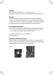
... features in this manual may be made by any form or by GIGABYTE without GIGABYTE's prior written permission. For product-related information, check on our website at: http://www.gigabyte.com Identifying Your Motherboard Revision The revision number on your motherboard revision before updating motherboard BIOS, drivers, or when looking for technical information. For example, "REV...
... features in this manual may be made by any form or by GIGABYTE without GIGABYTE's prior written permission. For product-related information, check on our website at: http://www.gigabyte.com Identifying Your Motherboard Revision The revision number on your motherboard revision before updating motherboard BIOS, drivers, or when looking for technical information. For example, "REV...
Manual
Page 4
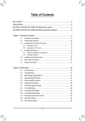
Table of Contents Box Contents...6 Optional Items...6 GA-PA65-D3-B3/GA-P61-USB3-B3 Motherboard Layout 7 GA-PA65-D3-B3/GA-P61-USB3-B3 Motherboard Block Diagram 8 Chapter 1 Hardware Installation 9 1-1 Installation Precautions 9 1-2 Product Specifications 10 1-3 Installing the CPU and CPU Cooler 13 1-3-1 Installing the CPU 13 1-3-2 Installing the CPU Cooler ...
Table of Contents Box Contents...6 Optional Items...6 GA-PA65-D3-B3/GA-P61-USB3-B3 Motherboard Layout 7 GA-PA65-D3-B3/GA-P61-USB3-B3 Motherboard Block Diagram 8 Chapter 1 Hardware Installation 9 1-1 Installation Precautions 9 1-2 Product Specifications 10 1-3 Installing the CPU and CPU Cooler 13 1-3-1 Installing the CPU 13 1-3-2 Installing the CPU Cooler ...
Manual
Page 6
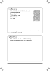
Optional Items 2-port USB 2.0 bracket (Part No. 12CR1-1UB030-5*R) 2-port SATA power cable (Part No. 12CF1-2SERPW-0*R) - 6 - Box Contents GA-PA65-D3-B3 or GA-P61-USB3-B3 motherboard Motherboard driver disk User's Manual Quick Installation Guide Two SATA cables I/O Shield • The box contents above are subject to change without notice. • The motherboard image is for reference only and the actual items shall depend on the product package you obtain. The box contents are for reference only.
Optional Items 2-port USB 2.0 bracket (Part No. 12CR1-1UB030-5*R) 2-port SATA power cable (Part No. 12CF1-2SERPW-0*R) - 6 - Box Contents GA-PA65-D3-B3 or GA-P61-USB3-B3 motherboard Motherboard driver disk User's Manual Quick Installation Guide Two SATA cables I/O Shield • The box contents above are subject to change without notice. • The motherboard image is for reference only and the actual items shall depend on the product package you obtain. The box contents are for reference only.
Manual
Page 7
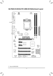
GA-PA65-D3-B3/GA-P61-USB3-B3 Motherboard Layout KB_MS_USB ATX_12V CPU_FAN COMA LPT COAXIAL LGA1155 ATX R_USB30 USB_LAN AUDIO F_AUDIO Etron EJ168 SYS_FAN1 PWR_FAN PCIEX16 BAT GA-PA65-D3-B3/ GA-P61-USB3-B3 Realtek RTL8111E PCIEX1_1 CODEC PCIEX1_2 SPDIF_O PCI1 M_BIOS B_BIOS iTE IT8728 PCI2 PCI3 SYS_FAN2 F_USB2 F_USB1 Intel® H61 CLR_CMOS iTE IT8892 Bridge F_PANEL DDR3_1 DDR3_2 SATA2_2 SATA2_3 SATA2_0 SATA2_1 GSATA3_4j GSATA3_5j Marvell 88SE9172j j Only for GA-PA65-D3-B3. - 7 -
GA-PA65-D3-B3/GA-P61-USB3-B3 Motherboard Layout KB_MS_USB ATX_12V CPU_FAN COMA LPT COAXIAL LGA1155 ATX R_USB30 USB_LAN AUDIO F_AUDIO Etron EJ168 SYS_FAN1 PWR_FAN PCIEX16 BAT GA-PA65-D3-B3/ GA-P61-USB3-B3 Realtek RTL8111E PCIEX1_1 CODEC PCIEX1_2 SPDIF_O PCI1 M_BIOS B_BIOS iTE IT8728 PCI2 PCI3 SYS_FAN2 F_USB2 F_USB1 Intel® H61 CLR_CMOS iTE IT8892 Bridge F_PANEL DDR3_1 DDR3_2 SATA2_2 SATA2_3 SATA2_0 SATA2_1 GSATA3_4j GSATA3_5j Marvell 88SE9172j j Only for GA-PA65-D3-B3. - 7 -
Manual
Page 8
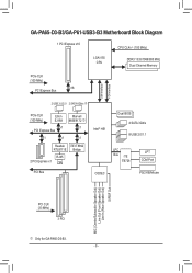
GA-PA65-D3-B3/GA-P61-USB3-B3 Motherboard Block Diagram 1 PCI Express x16 CPU CLK+/- (100 MHz) LGA1155 CPU DDR3 1333/1066/800 MHz Dual Channel Memory PCIe CLK (100 MHz) x16 PCI .../Mouse MIC (Center/Subwoofer Speaker Out) Line Out (Front Speaker Out) Line In (Rear Speaker Out) S/PDIF Out PCI CLK (33 MHz) 3 PCI j Only for GA-PA65-D3-B3. - 8 -
GA-PA65-D3-B3/GA-P61-USB3-B3 Motherboard Block Diagram 1 PCI Express x16 CPU CLK+/- (100 MHz) LGA1155 CPU DDR3 1333/1066/800 MHz Dual Channel Memory PCIe CLK (100 MHz) x16 PCI .../Mouse MIC (Center/Subwoofer Speaker Out) Line Out (Front Speaker Out) Line In (Rear Speaker Out) S/PDIF Out PCI CLK (33 MHz) 3 PCI j Only for GA-PA65-D3-B3. - 8 -
Manual
Page 9
...it on top of an antistatic pad or within an electrostatic shielding container. •• Before unplugging the power supply cable from the motherboard, make sure the power supply voltage has been set according to the use of your dealer. Prior to installation, carefully read the user...an ESD wrist strap, keep your hands dry and first touch a metal object to eliminate static electricity. •• Prior to installing the motherboard, please have a problem related to the local voltage standard. •• Before using the product, please verify that all cables and power ...
...it on top of an antistatic pad or within an electrostatic shielding container. •• Before unplugging the power supply cable from the motherboard, make sure the power supply voltage has been set according to the use of your dealer. Prior to installation, carefully read the user...an ESD wrist strap, keep your hands dry and first touch a metal object to eliminate static electricity. •• Prior to installing the motherboard, please have a problem related to the local voltage standard. •• Before using the product, please verify that all cables and power ...

Manual
Page 12
...ŠŠ Support for Xpress Install ŠŠ Support for Xpress Recovery2 ŠŠ Support for EasyTune * Available functions in EasyTune may differ by motherboard model. ŠŠ Support for Easy Energy Saver ŠŠ Support for Smart 6™ ŠŠ Support for Auto Green ŠŠ ...Operating System ŠŠ Support for Microsoft® Windows 7/Vista/XP Form Factor ŠŠ ATX Form Factor; 30.5cm x 19.0cm * GIGABYTE reserves the right to make any changes to the product specifications and product-related information without prior notice.
...ŠŠ Support for Xpress Install ŠŠ Support for Xpress Recovery2 ŠŠ Support for EasyTune * Available functions in EasyTune may differ by motherboard model. ŠŠ Support for Easy Energy Saver ŠŠ Support for Smart 6™ ŠŠ Support for Auto Green ŠŠ ...Operating System ŠŠ Support for Microsoft® Windows 7/Vista/XP Form Factor ŠŠ ATX Form Factor; 30.5cm x 19.0cm * GIGABYTE reserves the right to make any changes to the product specifications and product-related information without prior notice.
Manual
Page 13
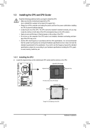
... One Marking on the computer if the CPU cooler is not recommended that the motherboard supports the CPU. (Go to GIGABYTE's website for the peripherals. It is not installed, otherwise overheating and dam- Locate the alignment keys on the motherboard CPU socket and the notches on the surface of the CPU. The CPU...
... One Marking on the computer if the CPU cooler is not recommended that the motherboard supports the CPU. (Go to GIGABYTE's website for the peripherals. It is not installed, otherwise overheating and dam- Locate the alignment keys on the motherboard CPU socket and the notches on the surface of the CPU. The CPU...
Manual
Page 14
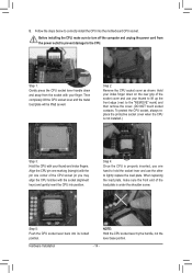
... front end of the CPU socket (or you may align the CPU notches with the socket alignment keys) and gently insert the CPU into the motherboard CPU socket. Step 2: Remove the CPU socket cover as well. NOTE: Hold the CPU socket lever by the handle, not the lever base portion. Then...
... front end of the CPU socket (or you may align the CPU notches with the socket alignment keys) and gently insert the CPU into the motherboard CPU socket. Step 2: Remove the CPU socket cover as well. NOTE: Hold the CPU socket lever by the handle, not the lever base portion. Then...
Manual
Page 15
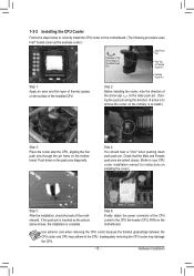
...the installation is to install.) Step 3: Place the cooler atop the CPU, aligning the four push pins through the pin holes on the motherboard. Inadequately removing the CPU cooler may adhere to the CPU. Hardware Installation Step 2: Before installing the cooler, note the direction of the ...arrow sign on the push pins diagonally. Step 6: Finally, attach the power connector of the motherboard. Push down each push pin. Step 4: You should hear a "click" when pushing down on the male push pin. (Turning the push pin...
...the installation is to install.) Step 3: Place the cooler atop the CPU, aligning the four push pins through the pin holes on the motherboard. Inadequately removing the CPU cooler may adhere to the CPU. Hardware Installation Step 2: Before installing the cooler, note the direction of the ...arrow sign on the push pins diagonally. Step 6: Finally, attach the power connector of the motherboard. Push down each push pin. Step 4: You should hear a "click" when pushing down on the male push pin. (Turning the push pin...

Manual
Page 16
... memory modules, it is installed, the BIOS will double the original memory bandwidth. After the memory is recommended that the motherboard supports the memory. The two DDR3 memory sockets are unable to CPU limitations, read the following : Channel 0: DDR3_1 Channel... DDR3_2 Due to insert the memory, switch the direction. 1-4-1 Dual Channel Memory Configuration This motherboard provides two DDR3 memory sockets and supports Dual Channel Technology. If you begin to GIGABYTE's website for optimum performance. Hardware Installation - 16 - It is recommended that memory of ...
... memory modules, it is installed, the BIOS will double the original memory bandwidth. After the memory is recommended that the motherboard supports the memory. The two DDR3 memory sockets are unable to CPU limitations, read the following : Channel 0: DDR3_1 Channel... DDR3_2 Due to insert the memory, switch the direction. 1-4-1 Dual Channel Memory Configuration This motherboard provides two DDR3 memory sockets and supports Dual Channel Technology. If you begin to GIGABYTE's website for optimum performance. Hardware Installation - 16 - It is recommended that memory of ...

Manual
Page 17
..., make sure to turn off the computer and unplug the power cord from the power outlet to prevent damage to install DDR3 DIMMs on this motherboard. Spread the retaining clips at both ends of the socket will snap into the memory socket. Step 2: The clips at both ends of the memory...
..., make sure to turn off the computer and unplug the power cord from the power outlet to prevent damage to install DDR3 DIMMs on this motherboard. Spread the retaining clips at both ends of the socket will snap into the memory socket. Step 2: The clips at both ends of the memory...
Manual
Page 18
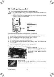
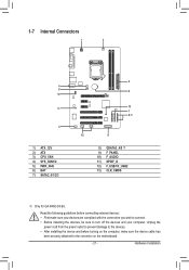
... slot. 333 Make sure the metal contacts on the top edge of the PCI Express slot to install an expansion card: • Make sure the motherboard supports the expansion card. 1-5 Installing an Expansion Card Read the following guidelines before installing an expansion card to prevent hardware damage. Hardware Installation - 18 - Remove...
... slot. 333 Make sure the metal contacts on the top edge of the PCI Express slot to install an expansion card: • Make sure the motherboard supports the expansion card. 1-5 Installing an Expansion Card Read the following guidelines before installing an expansion card to prevent hardware damage. Hardware Installation - 18 - Remove...

Manual
Page 19
... or receiving is occurring •• When removing the cable connected to an external audio system that your device and then remove it from the motherboard. •• When removing the cable, pull it side to side to connect devices such as a printer, scanner and etc. USB 3.0/2.0 Port The USB 3.0 port...
... or receiving is occurring •• When removing the cable connected to an external audio system that your device and then remove it from the motherboard. •• When removing the cable, pull it side to side to connect devices such as a printer, scanner and etc. USB 3.0/2.0 Port The USB 3.0 port...
Manual
Page 21
... 1 3 4 5 10 11 4 1) ATX_12V 2) ATX 3) CPU_FAN 4) SYS_FAN1/2 5) PWR_FAN 6) BAT 7) SATA2_0/1/2/3 2 6 13 7 8 j 12 9 8) GSATA3_4/5 j 9) F_PANEL 10) F_AUDIO 11) SPDIF_O 12) F_USB1/F_USB2 13) CLR_CMOS j Only for GA-PA65-D3-B3. Read the following guidelines before turning on the computer, make sure your devices are compliant with the connectors you wish to connect. ••...
... 1 3 4 5 10 11 4 1) ATX_12V 2) ATX 3) CPU_FAN 4) SYS_FAN1/2 5) PWR_FAN 6) BAT 7) SATA2_0/1/2/3 2 6 13 7 8 j 12 9 8) GSATA3_4/5 j 9) F_PANEL 10) F_AUDIO 11) SPDIF_O 12) F_USB1/F_USB2 13) CLR_CMOS j Only for GA-PA65-D3-B3. Read the following guidelines before turning on the computer, make sure your devices are compliant with the connectors you wish to connect. ••...
Manual
Page 22
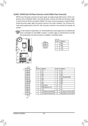
... be used (500W or greater). The power connector possesses a foolproof design. If the 12V power connector is turned off and all the components on the motherboard. 1/2) ATX_12V/ATX (2x2 12V Power Connector and 2x12 Main Power Connector) With the use of the power connector, the power supply can supply enough stable...
... be used (500W or greater). The power connector possesses a foolproof design. If the 12V power connector is turned off and all the components on the motherboard. 1/2) ATX_12V/ATX (2x2 12V Power Connector and 2x12 Main Power Connector) With the use of the power connector, the power supply can supply enough stable...
Manual
Page 23
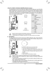
You may clear the CMOS values by your- 3/4/5) CPU_FAN/SYS_FAN1/SYS_FAN2/PWR_FAN (Fan Headers) The motherboard has a 4-pin CPU fan header (CPU_FAN), a 4-pin (SYS_FAN2) and a 3-pin (SYS_FAN1) system fan headers, and a 3-pin power fan header (PWR_FAN). When connecting a fan cable...the correct orientation (the black connector wire is turned off your computer and unplug the power cord. 222 Gently remove the battery from overheating. The motherboard supports CPU fan speed control, which requires the use a metal object like a screwdriver to the CPU or the system may be handled in ...
You may clear the CMOS values by your- 3/4/5) CPU_FAN/SYS_FAN1/SYS_FAN2/PWR_FAN (Fan Headers) The motherboard has a 4-pin CPU fan header (CPU_FAN), a 4-pin (SYS_FAN2) and a 3-pin (SYS_FAN1) system fan headers, and a 3-pin power fan header (PWR_FAN). When connecting a fan cable...the correct orientation (the black connector wire is turned off your computer and unplug the power cord. 222 Gently remove the battery from overheating. The motherboard supports CPU fan speed control, which requires the use a metal object like a screwdriver to the CPU or the system may be handled in ...
Manual
Page 26
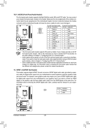
...97 Front Panel Audio: Pin No. If you wish to connect an HDMI display to this header. Incorrect connection between the module connector and the motherboard header will be present on how to certain expansion cards like graphics cards and sound cards. Pin No. You may require you to use a ... HD audio by expansion cards) for your chassis provides an AC'97 front panel audio module, refer to the instructions on both of the motherboard header. If your expansion card. Make sure the wire assignments of the module connector match the pin assignments of the front and back panel ...
...97 Front Panel Audio: Pin No. If you wish to connect an HDMI display to this header. Incorrect connection between the module connector and the motherboard header will be present on how to certain expansion cards like graphics cards and sound cards. Pin No. You may require you to use a ... HD audio by expansion cards) for your chassis provides an AC'97 front panel audio module, refer to the instructions on both of the motherboard header. If your expansion card. Make sure the wire assignments of the module connector match the pin assignments of the front and back panel ...

Manual
Page 27
... Values •• Always turn off your computer and unplug the power cord from the jumper. Failure to do so may cause damage to the motherboard. •• After system restart, go to BIOS Setup to load factory defaults (select Load Optimized Defaults) or manually configure the BIOS settings (refer to...
... Values •• Always turn off your computer and unplug the power cord from the jumper. Failure to do so may cause damage to the motherboard. •• After system restart, go to BIOS Setup to load factory defaults (select Load Optimized Defaults) or manually configure the BIOS settings (refer to...


