Manual
Page 4
Table of Contents Box Contents...6 Optional Items...6 GA-P55A-UD6 Motherboard Layout 7 Block Diagram...8 Chapter 1 Hardware Installation 9 1-1 Installation Precautions 9 1-2 Product Specifications 10 1-3 Installing the CPU and CPU Cooler 13 1-3-1 Installing the CPU 13 1-3-2 Installing the CPU Cooler 15 1-4 Installing the Memory 16 1-4-1 Dual Channel Memory Configuration 16 1-4-2 Installing a Memory 17 1-5 Installing an Expansion Card 18 1-6 Setup of...
Table of Contents Box Contents...6 Optional Items...6 GA-P55A-UD6 Motherboard Layout 7 Block Diagram...8 Chapter 1 Hardware Installation 9 1-1 Installation Precautions 9 1-2 Product Specifications 10 1-3 Installing the CPU and CPU Cooler 13 1-3-1 Installing the CPU 13 1-3-2 Installing the CPU Cooler 15 1-4 Installing the Memory 16 1-4-1 Dual Channel Memory Configuration 16 1-4-2 Installing a Memory 17 1-5 Installing an Expansion Card 18 1-6 Setup of...
Manual
Page 8
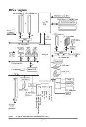
Block Diagram 2 PCI Express x8 1 PCI Express x16 LGA1156 or CPU CPU CLK+/- (133 MHz) DDR3 2200/1333/1066/800 MHz Dual Channel Memory PCIe CLK (100 MHz) x8 x16 Switch PCI Express Bus 2 USB 3.0/2.0 LAN1 LAN2 RJ45 RJ45 PCIe CLK (100 MHz) NEC RTL8111D RTL8111D x1 x1 x1 ...
Block Diagram 2 PCI Express x8 1 PCI Express x16 LGA1156 or CPU CPU CLK+/- (133 MHz) DDR3 2200/1333/1066/800 MHz Dual Channel Memory PCIe CLK (100 MHz) x8 x16 Switch PCI Express Bus 2 USB 3.0/2.0 LAN1 LAN2 RJ45 RJ45 PCIe CLK (100 MHz) NEC RTL8111D RTL8111D x1 x1 x1 ...
Manual
Page 9
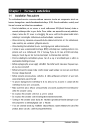
... leads or connectors. • It is best to wear an electrostatic discharge (ESD) wrist strap when handling electronic com- ponents such as a motherboard, CPU or memory. Hardware Installation Chapter 1 Hardware Installation 1-1 Installation Precautions The motherboard contains numerous delicate electronic circuits and components which can lead to damage to system components as...
... leads or connectors. • It is best to wear an electrostatic discharge (ESD) wrist strap when handling electronic com- ponents such as a motherboard, CPU or memory. Hardware Installation Chapter 1 Hardware Installation 1-1 Installation Precautions The motherboard contains numerous delicate electronic circuits and components which can lead to damage to system components as...
Manual
Page 10
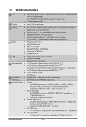
... sockets supporting up to 16 GB of system memory (Note 1) Dual channel memory architecture Support for DDR3 2200/1333/1066/800 MHz memory modules Support for non-ECC memory modules Support for Extreme Memory Profile (XMP) memory modules (Go to GIGABYTE's website for the latest memory support list.) Audio Realtek ALC889 codec ...
... sockets supporting up to 16 GB of system memory (Note 1) Dual channel memory architecture Support for DDR3 2200/1333/1066/800 MHz memory modules Support for non-ECC memory modules Support for Extreme Memory Profile (XMP) memory modules (Go to GIGABYTE's website for the latest memory support list.) Audio Realtek ALC889 codec ...

Manual
Page 12
... Form Factor; 30.5cm x 24.4cm (Note 1) Due to Windows Vista/XP 32-bit operating system limitation, when more than 4 GB of physical memory is installed, the actual memory size displayed will be less than 4 GB. (Note 2) For optimum performance, if only one PCI Express graphics card is to be installed, be...
... Form Factor; 30.5cm x 24.4cm (Note 1) Due to Windows Vista/XP 32-bit operating system limitation, when more than 4 GB of physical memory is installed, the actual memory size displayed will be less than 4 GB. (Note 2) For optimum performance, if only one PCI Express graphics card is to be installed, be...

Manual
Page 13
...motherboard CPU socket and the notches on the computer if the CPU cooler is not recommended that the motherboard supports the CPU. (Go to GIGABYTE's website for the peripherals. If you may locate the notches on both sides of the CPU and alignment keys on the CPU socket.)... Make sure that the system bus frequency be inserted if oriented incorrectly. (Or you wish to your hardware specifications including the CPU, graphics card, memory, hard drive, etc. 1-3-1 Installing the CPU A. The CPU cannot be set beyond the standard specifications, please do so according to set the frequency...
...motherboard CPU socket and the notches on the computer if the CPU cooler is not recommended that the motherboard supports the CPU. (Go to GIGABYTE's website for the peripherals. If you may locate the notches on both sides of the CPU and alignment keys on the CPU socket.)... Make sure that the system bus frequency be inserted if oriented incorrectly. (Or you wish to your hardware specifications including the CPU, graphics card, memory, hard drive, etc. 1-3-1 Installing the CPU A. The CPU cannot be set beyond the standard specifications, please do so according to set the frequency...

Manual
Page 16
...SS - - When enabling Dual Channel mode with two memory modules, be sure to install it is recommended that memory of the same capacity, brand, speed, and chips be used. (Go to GIGABYTE's website for optimum performance. A memory module can be installed in the DDR3_1 or DDR3_4. ...Dual Channel mode cannot be enabled if only one direction. If you begin to prevent hardware damage. • Memory modules have a foolproof design. DS/SS - ...
...SS - - When enabling Dual Channel mode with two memory modules, be sure to install it is recommended that memory of the same capacity, brand, speed, and chips be used. (Go to GIGABYTE's website for optimum performance. A memory module can be installed in the DDR3_1 or DDR3_4. ...Dual Channel mode cannot be enabled if only one direction. If you begin to prevent hardware damage. • Memory modules have a foolproof design. DS/SS - ...

Manual
Page 17
... on the left, place your memory modules in one direction. Step 1: Note the orientation of the memory socket. Step 2: The clips at both ends of the memory, push down on the memory and insert it can only fit in the memory sockets. Place the memory module on this motherboard. DDR3 ...DDR2 DIMMs are not compatible to each other or DDR DIMMs. Be sure to the memory module. Spread the retaining clips at both ends of the memory module. Hardware Installation 1-4-2 Installing a Memory Before installing a memory module, make sure to turn off the computer and unplug the power cord from the...
... on the left, place your memory modules in one direction. Step 1: Note the orientation of the memory socket. Step 2: The clips at both ends of the memory, push down on the memory and insert it can only fit in the memory sockets. Place the memory module on this motherboard. DDR3 ...DDR2 DIMMs are not compatible to each other or DDR DIMMs. Be sure to the memory module. Spread the retaining clips at both ends of the memory module. Hardware Installation 1-4-2 Installing a Memory Before installing a memory module, make sure to turn off the computer and unplug the power cord from the...

Manual
Page 23
1-9 Onboard LEDs and Buttons CPU VTT/Memory Phase Indicator LEDs This motherboard contains 4 phase indicator LEDs controlled by the system BIOS to improper plug/unplug actions. ACPI LEDs: S3_LED S0_LED S4_S5_LED ...excessive overvoltage or overloading occurs. Hardware Installation V_P_LED (CPU VTT): GD1: Normal working conditions (green LED) GD2: Excessive overvoltage or overloading (yellow LED) M_P_LED (Memory): MD1: Normal working conditions; The green LEDs light up under normal working conditions (green LED) MD2: Excessive overvoltage or overloading (yellow LED) ACPI LEDs The...
1-9 Onboard LEDs and Buttons CPU VTT/Memory Phase Indicator LEDs This motherboard contains 4 phase indicator LEDs controlled by the system BIOS to improper plug/unplug actions. ACPI LEDs: S3_LED S0_LED S4_S5_LED ...excessive overvoltage or overloading occurs. Hardware Installation V_P_LED (CPU VTT): GD1: Normal working conditions (green LED) GD2: Excessive overvoltage or overloading (yellow LED) M_P_LED (Memory): MD1: Normal working conditions; The green LEDs light up under normal working conditions (green LED) MD2: Excessive overvoltage or overloading (yellow LED) ACPI LEDs The...

Manual
Page 38
... effect. First enter the profile name (to erase the default profile name, use this function to load the BIOS settings from BIOS If your CPU, memory, etc. Standard CMOS Features Use this menu to 8 profiles (Profile 1-8) and name each profile. It allows you to restrict access to make changes. ...
... effect. First enter the profile name (to erase the default profile name, use this function to load the BIOS settings from BIOS If your CPU, memory, etc. Standard CMOS Features Use this menu to 8 profiles (Profile 1-8) and name each profile. It allows you to restrict access to make changes. ...
Manual
Page 39
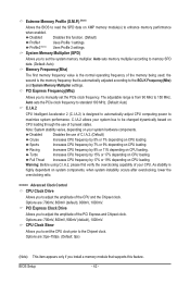
...Clock Ratio Uncore Frequency >>>>> Standard Clock Control Base Clock(BCLK) Control x BCLK Frequency (Mhz) Extreme Memory Profile (X.M.P.) (Note System Memory Multiplier (SPD) Memory Frequency (Mhz) 1333 PCI Express Frequency (Mhz) C.I.A.2 >>>>> Advanced Clock Control CPU Clock Drive PCI ...Press Enter] [Press Enter] [Press Enter] Item Help Menu Level BIOS Version BCLK CPU Frequency Memory Frequency Total Memory Size CPU Temperature PCH Temperature Vcore DRAM Voltage D1 133.27 MHz 3198.42 MHz 1332.80 MHz 1024 ...
...Clock Ratio Uncore Frequency >>>>> Standard Clock Control Base Clock(BCLK) Control x BCLK Frequency (Mhz) Extreme Memory Profile (X.M.P.) (Note System Memory Multiplier (SPD) Memory Frequency (Mhz) 1333 PCI Express Frequency (Mhz) C.I.A.2 >>>>> Advanced Clock Control CPU Clock Drive PCI ...Press Enter] [Press Enter] [Press Enter] Item Help Menu Level BIOS Version BCLK CPU Frequency Memory Frequency Total Memory Size CPU Temperature PCH Temperature Vcore DRAM Voltage D1 133.27 MHz 3198.42 MHz 1332.80 MHz 1024 ...
Manual
Page 42
..., 800mV, 900mV (default), 1000mV. CPU Clock Skew Allows you to memory SPD data. (Default: Auto) Memory Frequency(Mhz) The first memory frequency value is from 90 MHz to manually set the system memory multiplier. System Memory Multiplier (SPD) Allows you to set the CPU clock prior to the...frequency to standard 100 MHz. (Default: Auto) C.I.A.2 CPU Intelligent Accelerator 2 (C.I .A.2 allows your system bus to adjust the amplitude of the memory being used; Sports Increases CPU frequency by 17% or 19% depending on CPU loading. Full Thrust Increases CPU frequency by 7% or 9% depending ...
..., 800mV, 900mV (default), 1000mV. CPU Clock Skew Allows you to memory SPD data. (Default: Auto) Memory Frequency(Mhz) The first memory frequency value is from 90 MHz to manually set the system memory multiplier. System Memory Multiplier (SPD) Allows you to set the CPU clock prior to the...frequency to standard 100 MHz. (Default: Auto) C.I.A.2 CPU Intelligent Accelerator 2 (C.I .A.2 allows your system bus to adjust the amplitude of the memory being used; Sports Increases CPU frequency by 17% or 19% depending on CPU loading. Full Thrust Increases CPU frequency by 7% or 9% depending ...

Manual
Page 43
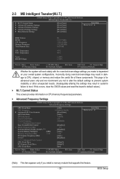
...1 settings. DRAM Timing Selectable (SPD) Quick and Expert allows the Channel Interleaving and Rank Interleaving items to enhance memory performance when enabled. Turbo Lets the system operate at its good performance level. (Default) Extreme Lets the system ...levels. Profile2 (Note) Uses Profile 2 settings. Advanced Memory Settings CMOS Setup Utility-Copyright (C) 1984-2009 Award Software Advanced Memory Settings Extreme Memory Profile (X.M.P.) (Note) System Memory Multiplier (SPD) Memory Frequency (Mhz) 1333 Performance Enhance DRAM Timing Selectable (SPD) Profile...
...1 settings. DRAM Timing Selectable (SPD) Quick and Expert allows the Channel Interleaving and Rank Interleaving items to enhance memory performance when enabled. Turbo Lets the system operate at its good performance level. (Default) Extreme Lets the system ...levels. Profile2 (Note) Uses Profile 2 settings. Advanced Memory Settings CMOS Setup Utility-Copyright (C) 1984-2009 Award Software Advanced Memory Settings Extreme Memory Profile (X.M.P.) (Note) System Memory Multiplier (SPD) Memory Frequency (Mhz) 1333 Performance Enhance DRAM Timing Selectable (SPD) Profile...

Manual
Page 48
... Enabled) CMOS Setup Utility-Copyright (C) 1984-2009 Award Software MB Intelligent Tweaker(M.I.T.) } M.I.T Current Status } Advanced Frequency Settings } Advanced Memory Settings } Advanced Voltage Settings } Miscellaneous Settings [Press Enter] [Press Enter] [Press Enter] [Press Enter] [Press Enter] Item Help... Menu Level BIOS Version BCLK CPU Frequency Memory Frequency Total Memory Size D1 133.27 MHz 3198.42 MHz 1332.80 MHz 1024 MB CPU Temperature PCH Temperature 45oC 40oC Vcore...
... Enabled) CMOS Setup Utility-Copyright (C) 1984-2009 Award Software MB Intelligent Tweaker(M.I.T.) } M.I.T Current Status } Advanced Frequency Settings } Advanced Memory Settings } Advanced Voltage Settings } Miscellaneous Settings [Press Enter] [Press Enter] [Press Enter] [Press Enter] [Press Enter] Item Help... Menu Level BIOS Version BCLK CPU Frequency Memory Frequency Total Memory Size D1 133.27 MHz 3198.42 MHz 1332.80 MHz 1024 MB CPU Temperature PCH Temperature 45oC 40oC Vcore...

Manual
Page 49
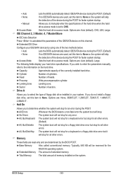
...None] [None] [None] [None] [None] [None] [None] [None] [None] [None] Drive A [1.44M, 3.5"] Halt On [All, But Keyboard] Base Memory 640K Move Enter: Select F5: Previous Values +/-/PU/PD: Value F10: Save F6: Fail-Safe Defaults ESC: Exit F1: General Help F7: Optimized Defaults CMOS... Setup Utility-Copyright (C) 1984-2009 Award Software Standard CMOS Features Extended Memory Total Memory 1022M 1024M Item Help Menu Level Move Enter: Select F5: Previous Values +/-/PU/PD: Value F10: Save F6...
...None] [None] [None] [None] [None] [None] [None] [None] [None] [None] Drive A [1.44M, 3.5"] Halt On [All, But Keyboard] Base Memory 640K Move Enter: Select F5: Previous Values +/-/PU/PD: Value F10: Save F6: Fail-Safe Defaults ESC: Exit F1: General Help F7: Optimized Defaults CMOS... Setup Utility-Copyright (C) 1984-2009 Award Software Standard CMOS Features Extended Memory Total Memory 1022M 1024M Item Help Menu Level Move Enter: Select F5: Previous Values +/-/PU/PD: Value F10: Save F6...
Manual
Page 50
... for a keyboard error but stop for all other errors. (Default) All, But Diskette The system boot will stop. Base Memory Also called conventional memory. Extended Memory The amount of cylinders. IDE Channel 2, 3 Master, 4, 7 Master/Slave IDE Auto-Detection Press to autodetect the parameters of...display your IDE/SATA devices by the BIOS POST. Capacity Approximate capacity of heads. Landing Zone Landing zone. Sector Number of memory installed on the system. Halt On Allows you to manually enter the specifications of the device during the POST for an ...
... for a keyboard error but stop for all other errors. (Default) All, But Diskette The system boot will stop. Base Memory Also called conventional memory. Extended Memory The amount of cylinders. IDE Channel 2, 3 Master, 4, 7 Master/Slave IDE Auto-Detection Press to autodetect the parameters of...display your IDE/SATA devices by the BIOS POST. Capacity Approximate capacity of heads. Landing Zone Landing zone. Sector Number of memory installed on the system. Halt On Allows you to manually enter the specifications of the device during the POST for an ...

Manual
Page 51
... is required for booting the system and for entering the operating system and to accept. This feature allows your hard drive. to 3 (Note) No-Execute Memory Protect (Note) Delay For HDD (Secs) Full Screen LOGO Show Backup BIOS Image to issue warnings when a third party hardware monitor utility is installed. (Default...
... is required for booting the system and for entering the operating system and to accept. This feature allows your hard drive. to 3 (Note) No-Execute Memory Protect (Note) Delay For HDD (Secs) Full Screen LOGO Show Backup BIOS Image to issue warnings when a third party hardware monitor utility is installed. (Default...

Manual
Page 52
... message. (Default: Enabled) Backup BIOS Image to HDD Allows the system to copy the BIOS image file to Disabled for the BIOS to display the GIGABYTE Logo at system startup. PEG2 Sets the PCI Express graphics card on the PCIEX16_1 slot as the first display. (Note) This item is corrupted, it... visit Intel's website. BIOS Setup - 52 - to 3 (Note) Allows you to determine whether to initialize the hard drive as Windows NT4.0. (Default: Disabled) No-Execute Memory Protect (Note) Enables or disables Intel Execute Disable Bit function.
... message. (Default: Enabled) Backup BIOS Image to HDD Allows the system to copy the BIOS image file to Disabled for the BIOS to display the GIGABYTE Logo at system startup. PEG2 Sets the PCI Express graphics card on the PCIEX16_1 slot as the first display. (Note) This item is corrupted, it... visit Intel's website. BIOS Setup - 52 - to 3 (Note) Allows you to determine whether to initialize the hard drive as Windows NT4.0. (Default: Disabled) No-Execute Memory Protect (Note) Enables or disables Intel Execute Disable Bit function.

Manual
Page 58
... 64-bit Windows 7/Vista. Disabled Disables this function, you to select the HPET mode for the password, press again without entering the password to Password. Memory The system returns to its last known awake state upon the return of the AC power, or the settings may not be effective. To turn...
... 64-bit Windows 7/Vista. Disabled Disables this function, you to select the HPET mode for the password, press again without entering the password to Password. Memory The system returns to its last known awake state upon the return of the AC power, or the settings may not be effective. To turn...

Manual
Page 69
... and drivers are attached to the first IDE and the first SATA connectors, the hard drive on your system data and perform restoration of system memory • VESA compatible graphics card • Windows XP with Xpress Recovery cannot be restored using Xpress Recovery2. • USB hard drives are different utilities...
... and drivers are attached to the first IDE and the first SATA connectors, the hard drive on your system data and perform restoration of system memory • VESA compatible graphics card • Windows XP with Xpress Recovery cannot be restored using Xpress Recovery2. • USB hard drives are different utilities...


